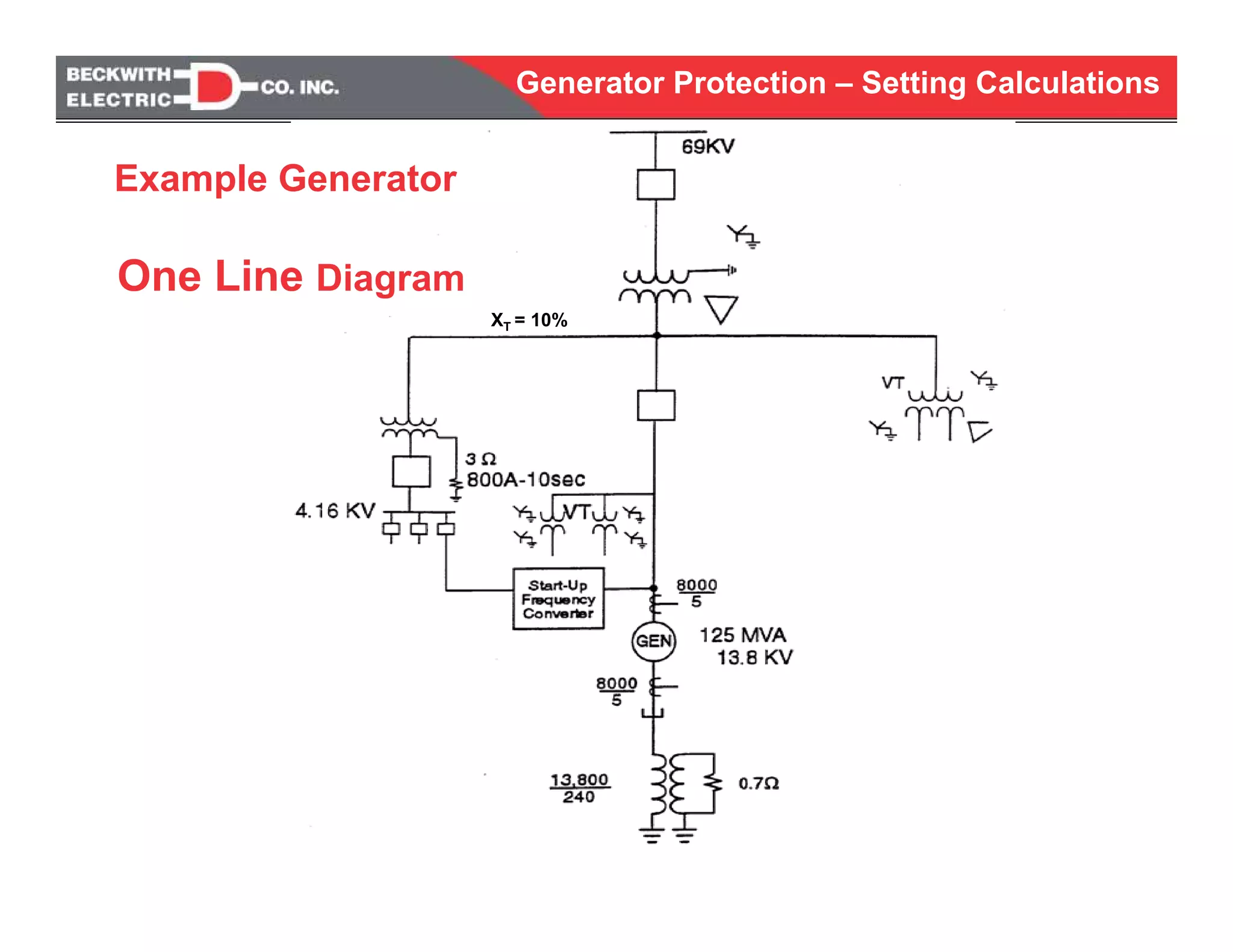
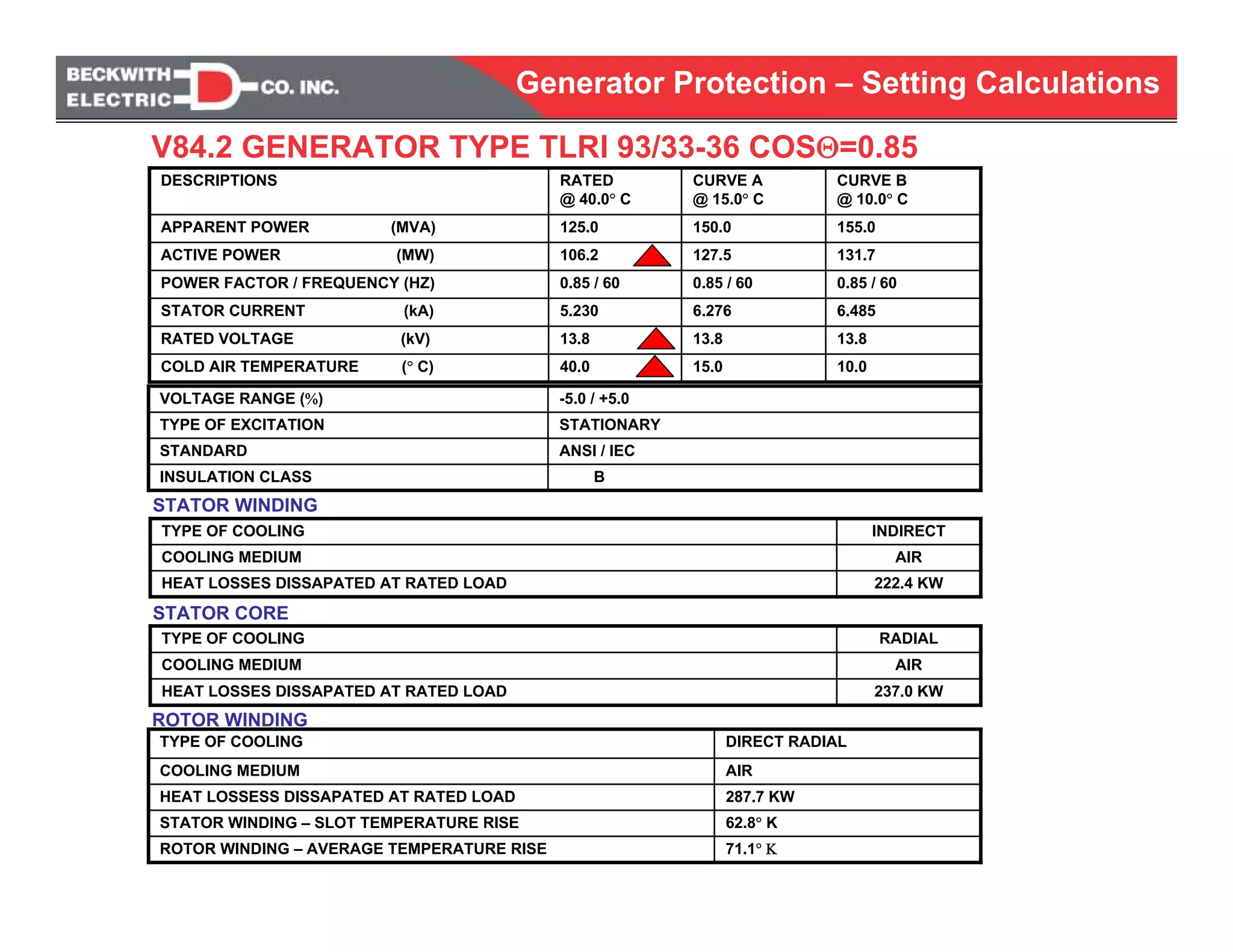
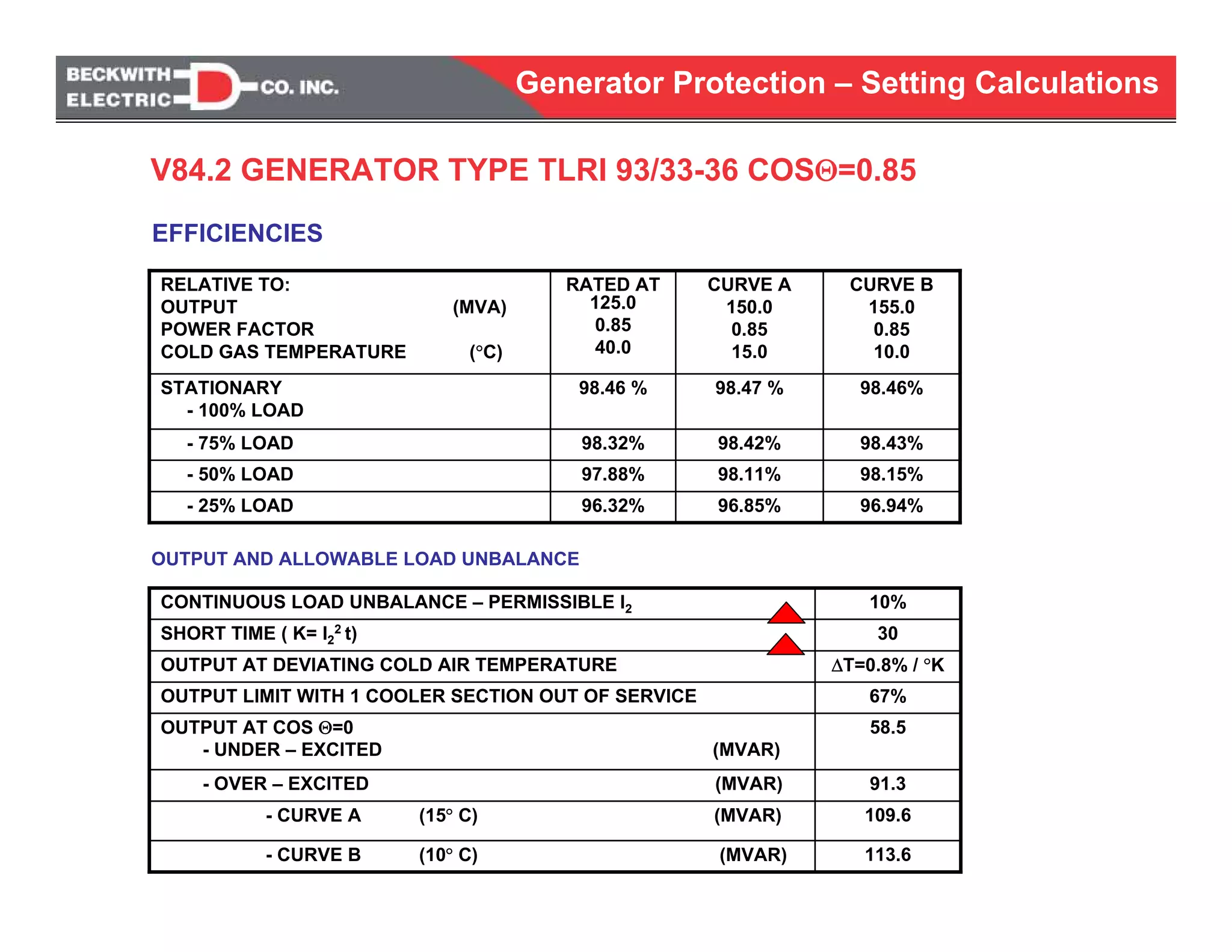
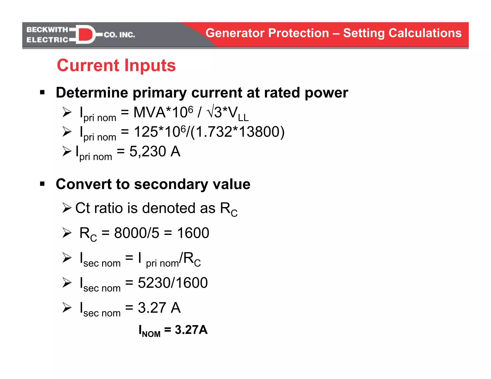
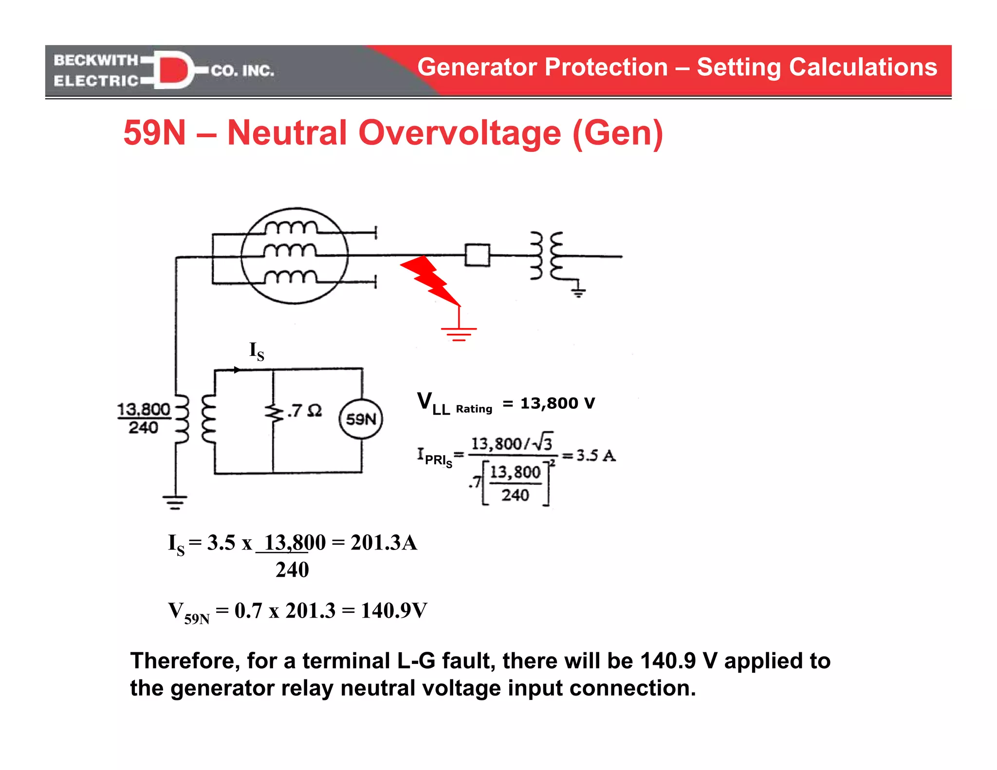
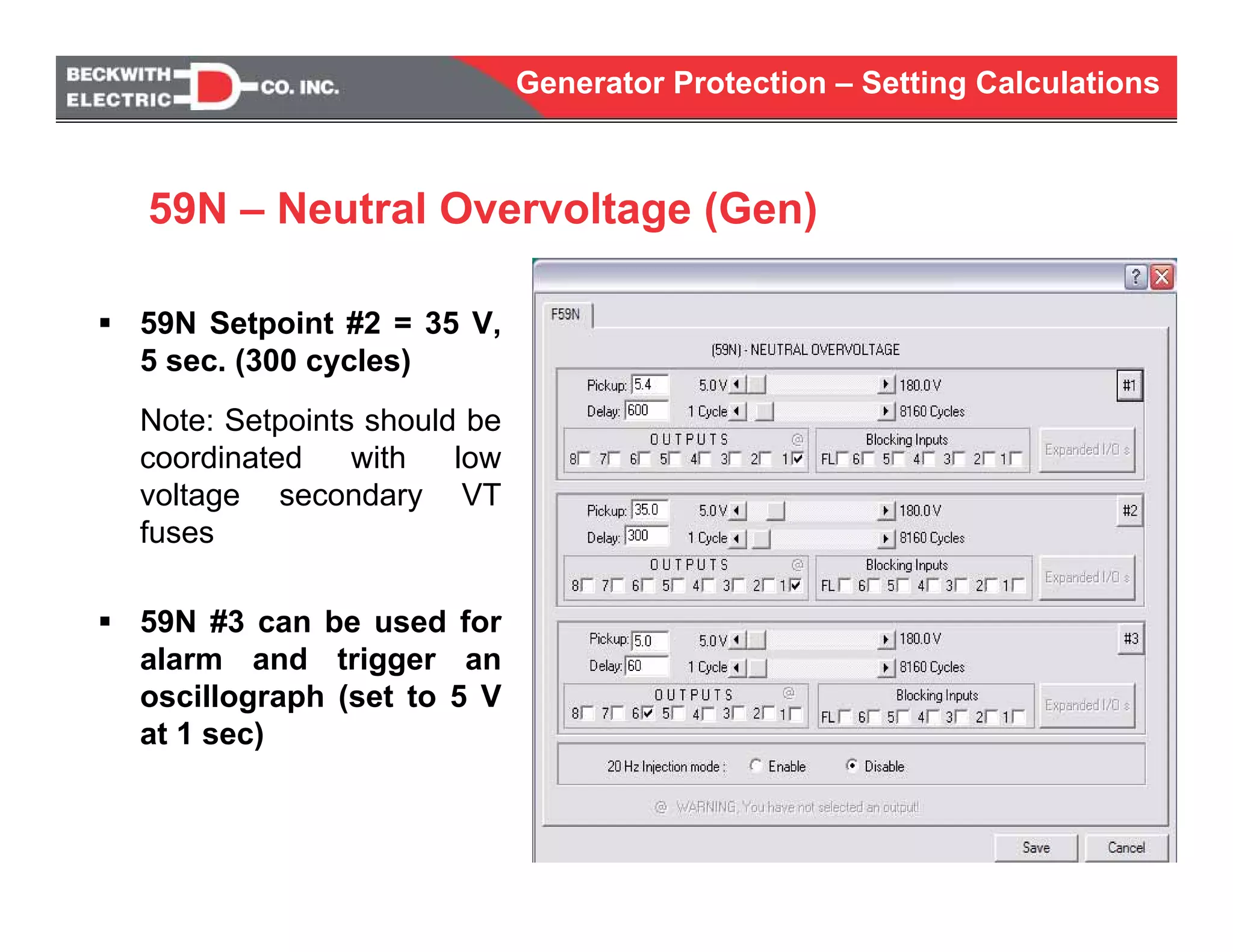
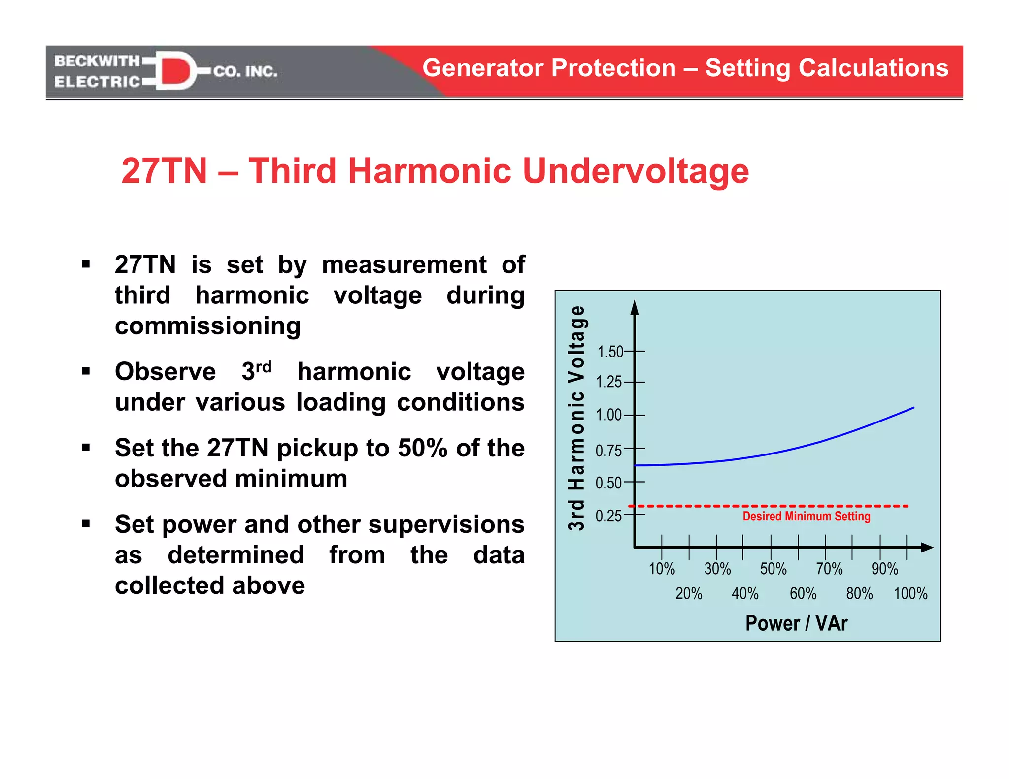
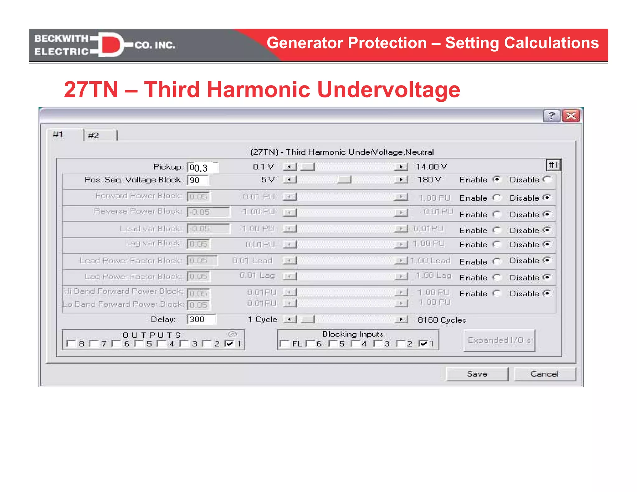
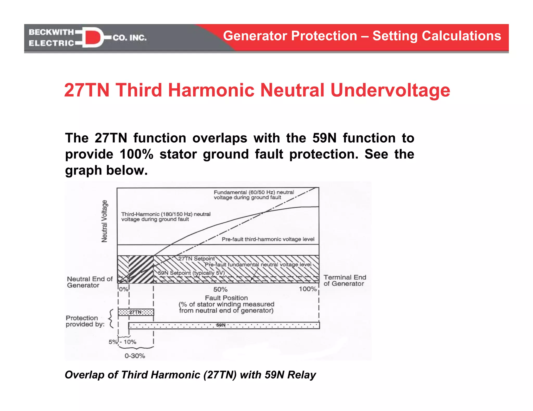
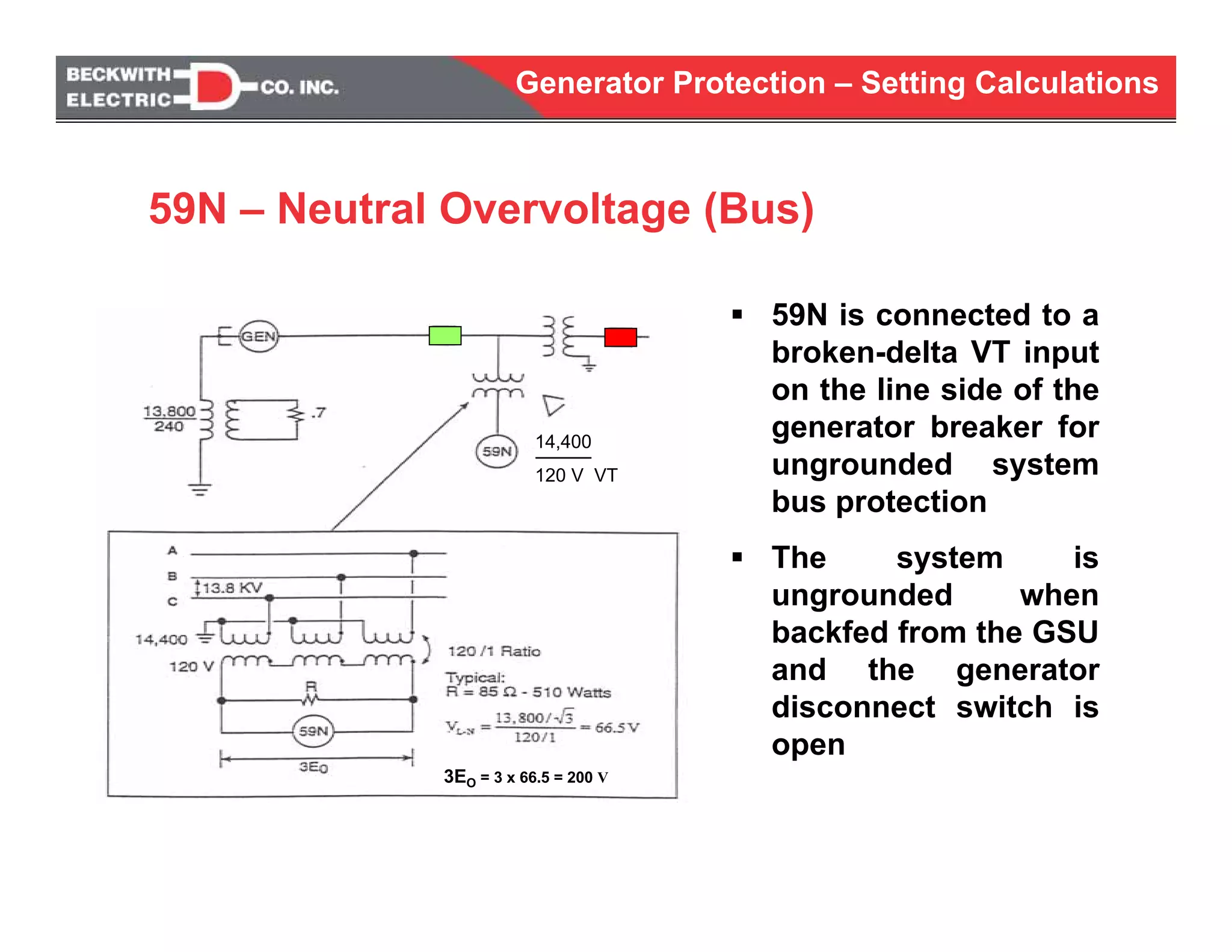
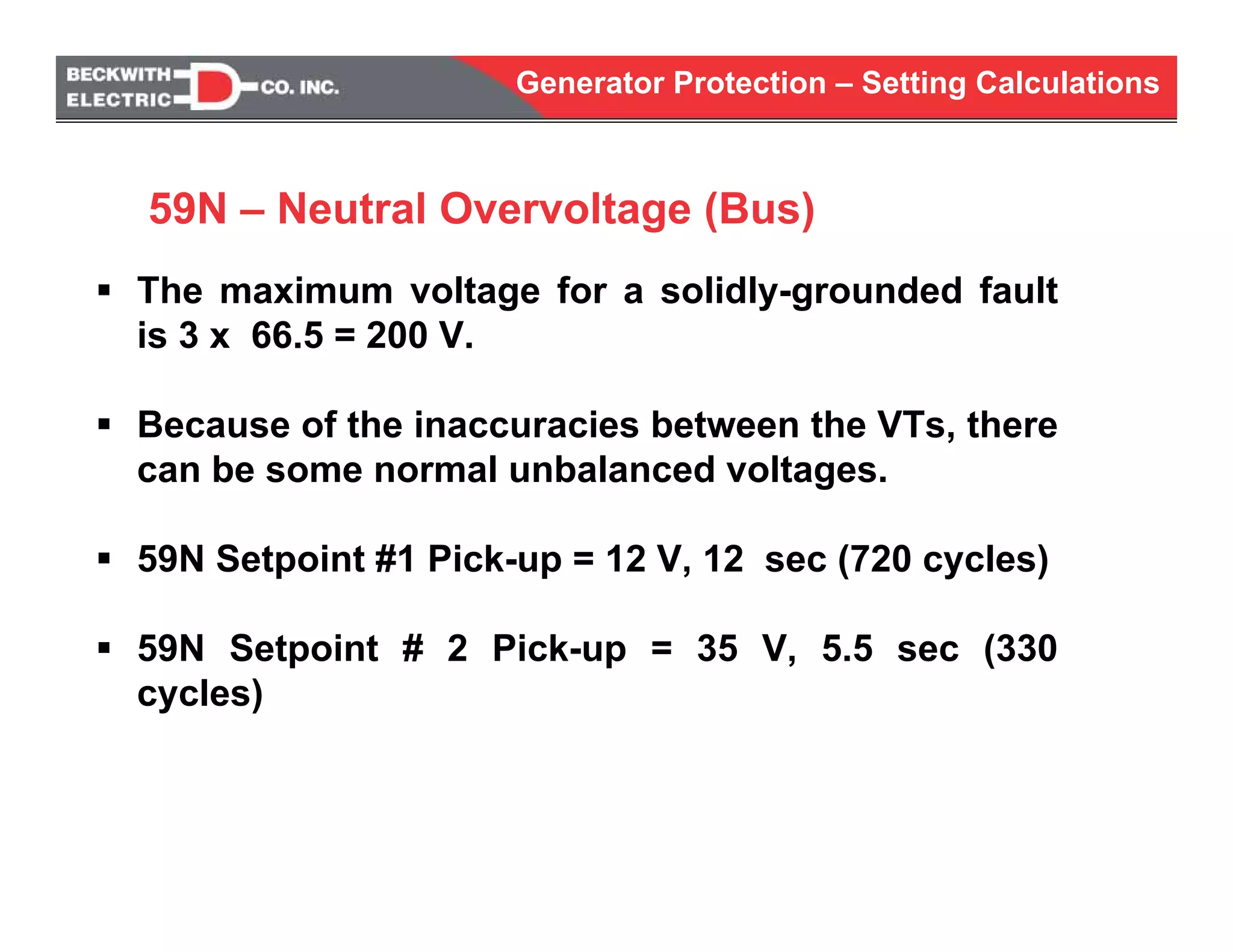
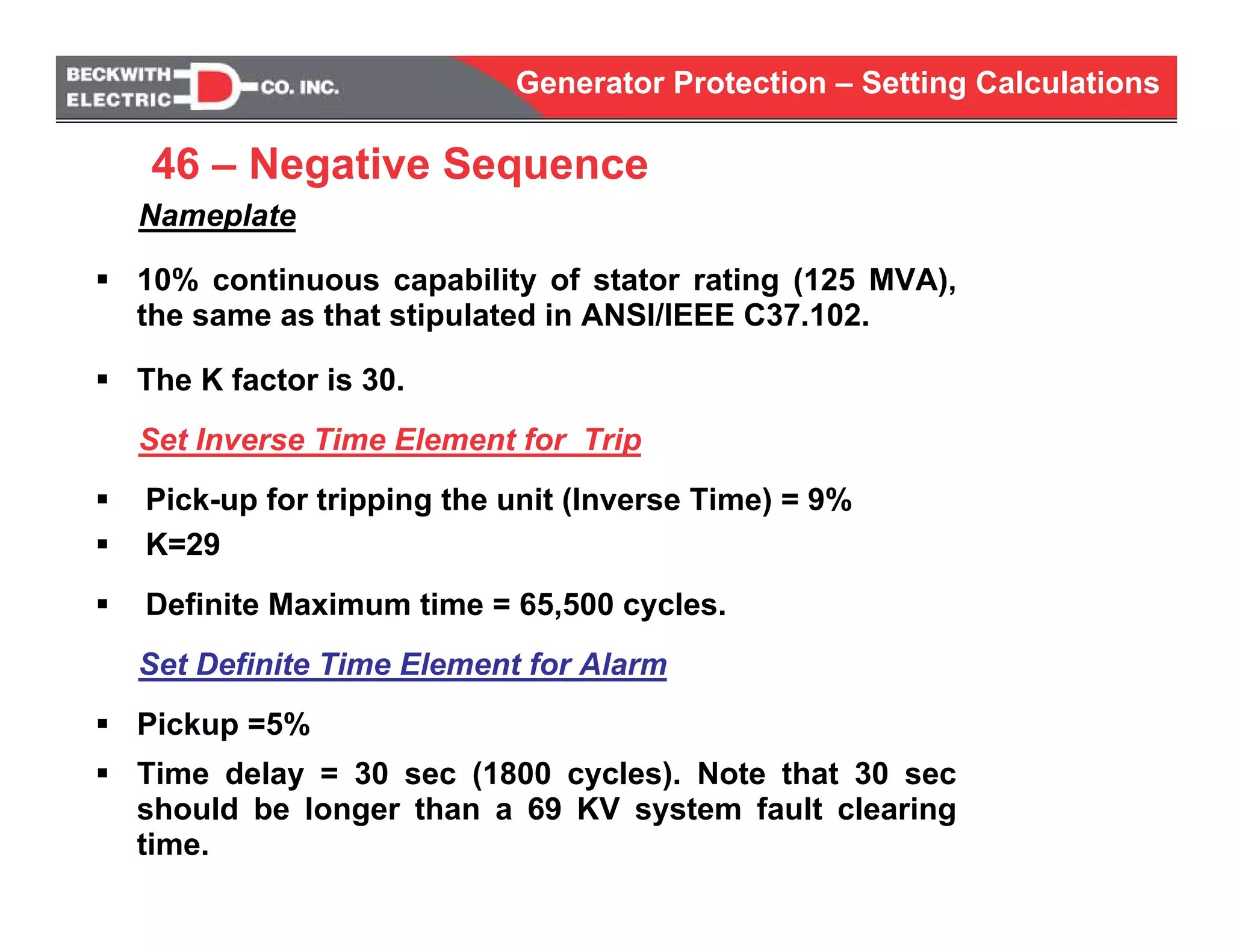
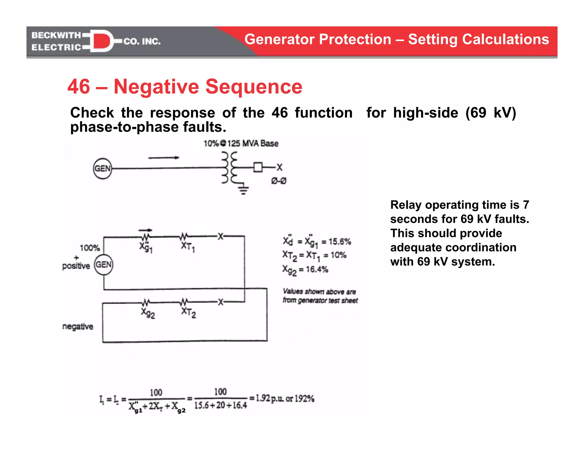
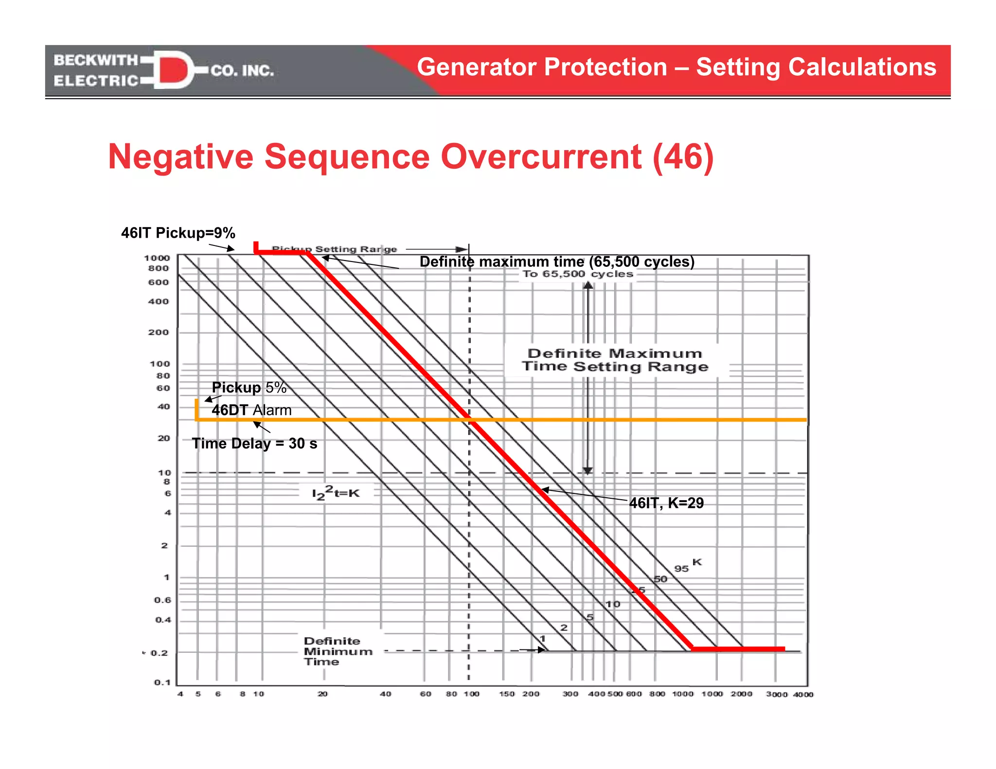
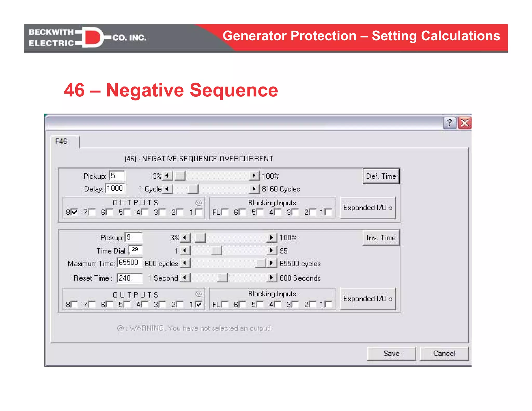
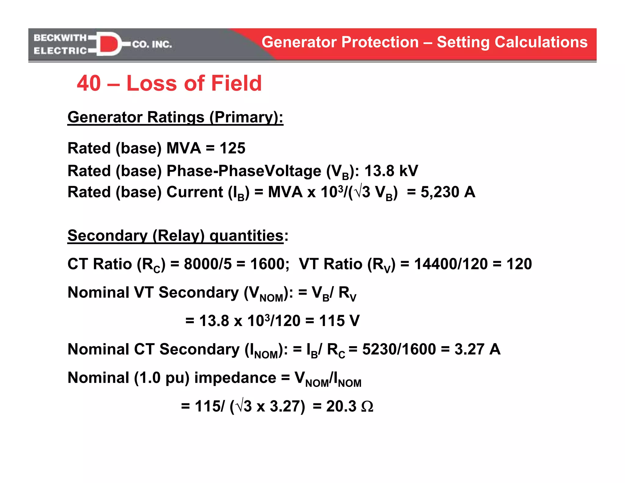
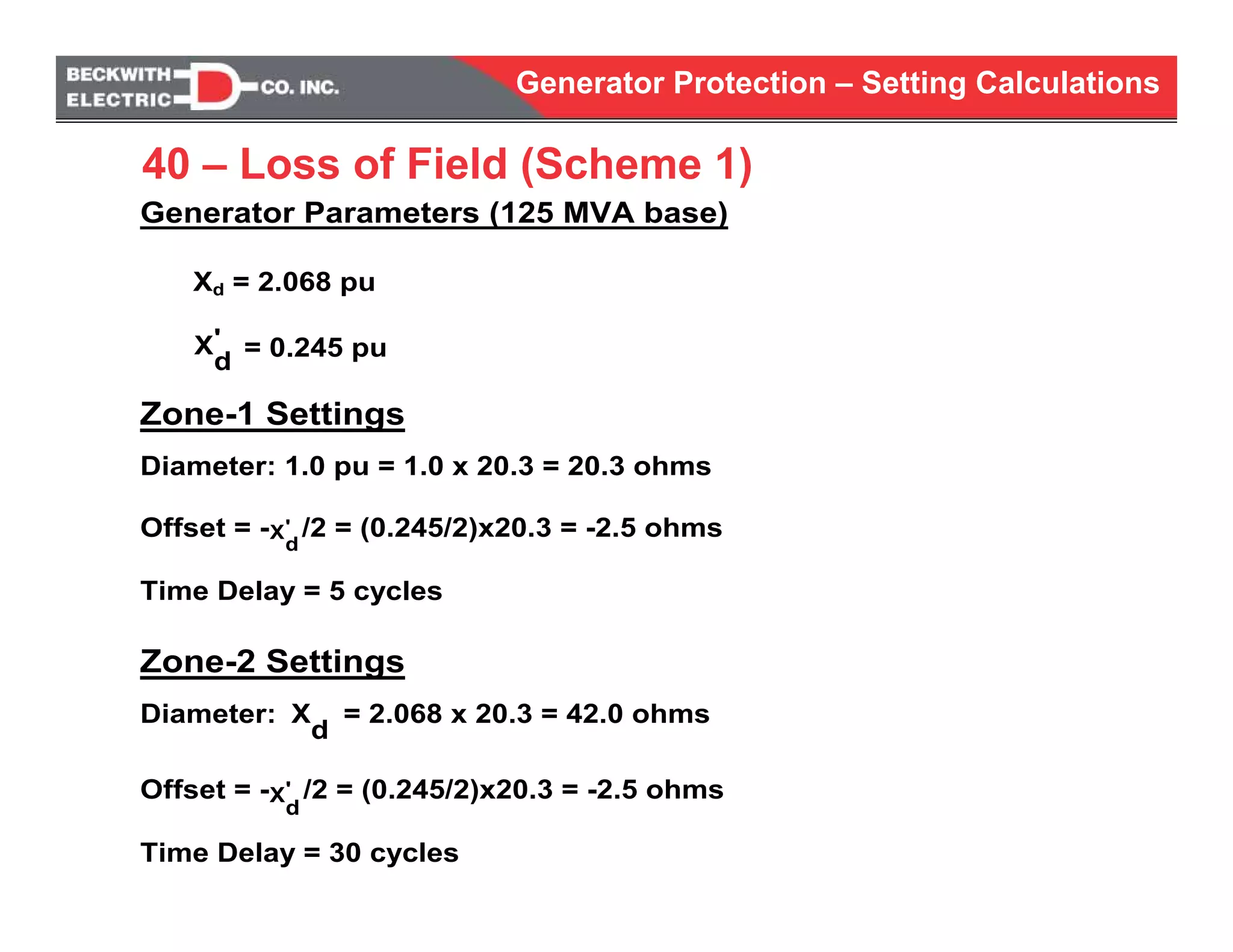
Generator ProtectionGenerator Protection
Relay Setting Calculations
Generator Protection – Setting Calculations
Generator Protection
Sample Relay Setting Calculations
The sample calculations shown here illustrate
steps involved in calculating the relay settings for
generator protection.
Other methodologies and techniques may be
applied to calculate relay settings based on
specific applications.
Generator Protection – Setting Calculations
XT = 10%
One Line Diagram
Example Generator
Generator Protection – Setting Calculations
10.015.040.0COLD AIR TEMPERATURE (° C)
13.813.813.8RATED VOLTAGE (kV)
6.4856.2765.230STATOR CURRENT (kA)
0.85 / 600.85 / 600.85 / 60POWER FACTOR / FREQUENCY (HZ)
131.7127.5106.2ACTIVE POWER (MW)
155.0150.0125.0APPARENT POWER (MVA)
CURVE B
@ 10.0° C
CURVE A
@ 15.0° C
RATED
@ 40.0° C
DESCRIPTIONS
BINSULATION CLASS
ANSI / IECSTANDARD
STATIONARYTYPE OF EXCITATION
-5.0 / +5.0VOLTAGE RANGE (%)
V84.2 GENERATOR TYPE TLRI 93/33-36 COSΘ=0.85
222.4 KWHEAT LOSSES DISSAPATED AT RATED LOAD
AIRCOOLING MEDIUM
INDIRECTTYPE OF COOLING
STATOR WINDING
237.0 KWHEAT LOSSES DISSAPATED AT RATED LOAD
AIRCOOLING MEDIUM
RADIALTYPE OF COOLING
STATOR CORE
71.1° ΚROTOR WINDING – AVERAGE TEMPERATURE RISE
62.8° KSTATOR WINDING – SLOT TEMPERATURE RISE
287.7 KWHEAT LOSSESS DISSAPATED AT RATED LOAD
AIRCOOLING MEDIUM
DIRECT RADIALTYPE OF COOLING
ROTOR WINDING
Generator Protection – Setting Calculations
96.94%96.85%96.32%- 25% LOAD
98.15%98.11%97.88%- 50% LOAD
98.43%98.42%98.32%- 75% LOAD
98.46%98.47 %98.46 %STATIONARY
- 100% LOAD
CURVE B
155.0
0.85
10.0
CURVE A
150.0
0.85
15.0
RATED AT
125.0
0.85
40.0
RELATIVE TO:
OUTPUT (MVA)
POWER FACTOR
COLD GAS TEMPERATURE (°C)
EFFICIENCIES
113.6- CURVE B (10° C) (MVAR)
109.6- CURVE A (15° C) (MVAR)
91.3- OVER – EXCITED (MVAR)
58.5OUTPUT AT COS Θ=0
- UNDER – EXCITED (MVAR)
67%OUTPUT LIMIT WITH 1 COOLER SECTION OUT OF SERVICE
ΔT=0.8% / °KOUTPUT AT DEVIATING COLD AIR TEMPERATURE
30SHORT TIME ( K= I2
2
t)
10%CONTINUOUS LOAD UNBALANCE – PERMISSIBLE I2
OUTPUT AND ALLOWABLE LOAD UNBALANCE
V84.2 GENERATOR TYPE TLRI 93/33-36 COSΘ=0.85
Generator Protection – Setting Calculations
- -- -395 18825% LOAD
- -- -519 24750% LOAD
- -- -662 31475% LOAD
1003 476970 459822 391100% LOAD
- -- -1011 480125% LOAD
- -- -298 142NO LOAD
CURVE B
@10.0° C
CURRENT FIELD
VOLTAGE
(A) (V)
CURVE A
@15.0° C
CURRENT FIELD
VOLTAGE
(A) (V)
RATED
@ 40.0° C
CURRENT FIELD
VOLTAGE
(A) (V)
GENERATOR
LOAD
GENERATOR – EXCITER CURRENTS AND VOLTAGES
EXCITER CURRENTS AND VOLTAGES
--15.1%XSLGSTATOR LEAKAGE
--26.8%XPPOTIER
--10.9%X0ZERO PHASE SEQUENCE
16.4%X2 SAT20.3%X2 UNSATNEG PHASE SEQUENCE
--196.4%XQ UNSATQ-AXIS SYNCHRONOUS
46.1%XQ′ SAT51.3%XQ′ UNSATQ-AXIS TRANSIENT
17.2%XQ″ SAT21.2%XQ ″ UNSATQ-AXIS SUB-TRANSIENT
--206.8%XD UNSATD-AXIS SYNCHRONOUS
24.5%XD′ SAT27.2%XD′ UNSATD-AXIS TRANSIENT
15.6%XD″ SAT19.3%XD ″ UNSATD-AXIS SUB-TRANSIENT
REACTANCES BASE MVA = 125 MVA
0.57NO LOAD SHORT CIRCUIT RATIO SAT.
V84.2 GENERATOR TYPE TLRI 93/33-36 COSΘ=0.85
Generator Protection – Setting Calculations
--0.030 STADC TIME CONSTRAINT
2.500 STQO΄ NO-LOAD0.534 STQ΄ SHORT
CIRCUIT
Q-AXIS TRANSIENT
0.150 STQO΄΄ NO-LOAD0.068 SXQ΄΄ SHORT
CIRCUIT
Q-AXIS SUB-TRANSIENT
7.150 STDO΄ NO-LOAD0.873 STD΄ SHORT
CIRCUIT
D-AXIS TRANSIENT
0.045 STDO΄΄ NO-LOAD0.031 SXD΄΄ SHORT
CIRCUIT
D-AXIS SUB-TRANSIENT
TIME CONSTANTS
0.267%R0NULL SEQUENCE
3.201%R2INVERSE SEQUENCE
0.367%R1POSITIVE SEQUENCE
0.3501 ΩRF20OF ROTOR WINDINGS @20° C
0.001674 ΩRA20OF STATOR WINDINGS @20° C
RESISTANCES
V84.2 GENERATOR TYPE TLRI 93/33-36 COSΘ=0.85
Generator Protection – Setting Calculations
Voltages and currents that are present
at the input terminals when the
generator is operating at rated voltage
and current.
Nominal Voltages and Currents
Generator Protection – Setting Calculations
Voltage Inputs and their connections
3V0
.
.
Generator Protection – Setting Calculations
A B C
A
B
C
13.8kVLL
VT Ratio = 14,440 / 120 = 120
13,800 / 120 = 115 V
VT Type: Line-to-Line
VNOM = 115 V
Voltage Inputs
Open Delta-Open Delta VT, secondary wired L-L Example
Generator Protection – Setting Calculations
VT Type: Line-to-Line
VNOM = 115 V
Example:
Generator rating VL-L = 13,800V
VT Ratio = 14,400/120V = 120/1
Voltage Inputs, 3Y-3Y VT, secondary wired L-L Example
M-3425A
13,800V
13,800/120 = 115
= 120
Generator Protection – Setting Calculations
Example:
Generator rating VL-L = 13,800V
VT Ratio = 14,400/120V = 120
A
B
C
13,800
√3
13,800 V
VT Ratio = 14,410
120V
a
b
c
V
NOMINAL
= 115
√3 =66.5 Line-to-Ground
14,440
120
VT Type: Line-to-Ground
VNOM = 115/√3 = 66.4 V
3Y-3Y VT, secondary wired L-G Example
Voltage Inputs
Generator Protection – Setting Calculations
The “Line-Ground to Line-Line” selection should be used
when it is desired to provide the phase voltage-based
elements (27, 59, 24 functions) with phase-to-phase voltages
They will not operate for neutral shifts that can occur during
stator ground faults on high impedance grounded generators
The oscillograph in the relays will record line-ground voltage
to provide stator ground fault phase identification
Voltage Inputs
3Y-3Y VT, secondary wired L-G (L-G to L-L selection)
Use of L-L Quantities for Phase Voltage-based elements
Generator Protection – Setting Calculations
A ground fault will cause LG connected phase elements
through a 3Y-3Y VT to have undervoltage or overvoltage
(depending on faulted phase)
System
High
Impedance
Ground
SLG
A
B
C
a
bc
a
bc
ground
Van
=Vag
Vbn
=Vbg
Vbn
=Vbg
n=g
vag=0
n
Van= -Vng
Vcn Vbn
Vbg
Vcg
Neutral Shift on Ground Fault:
High Impedance Grounded Generator
Fault
Generator Protection – Setting Calculations
Generator rating VL-L = 13,800V
VT Ratio = 14,400/120V
A
B
C
13,800
√3
13,800 V
VT Ratio = 14,410
120V
a
b
c
V
NOMINAL
= 115
√3 =66.5 Line-to-Ground
14,440
120
VT Type: LG to LL
VNOM = 115 V
Software converts
LG (66.5V) voltages to
LL (115V) quantities
Voltage Inputs
3Y-3Y VT, secondary wired L-G (L-G to L-L selection on
the relay). This selection is recommended for the
example generator.
(66.4V)
Generator Protection – Setting Calculations
Determine primary current at rated power
Ipri nom = MVA*106 / √3*VLL
Ipri nom = 125*106/(1.732*13800)
Ipri nom = 5,230 A
Convert to secondary value
Ct ratio is denoted as RC
RC = 8000/5 = 1600
Isec nom = I pri nom/RC
Isec nom = 5230/1600
Isec nom = 3.27 A
INOM = 3.27A
Current Inputs
Generator Protection – Setting Calculations
Delta-Y transform setting (used with 21, 51V)
This setting Determines calculation used for 21
and 51V functions (calculates the GSU high side
voltages and currents)
• Disable: Used for YY and Delta/Delta
connected transformers
• Delta-AB: Used for Delta-AB/Y connected
transformers
• Delta-AC: Used for Delta-AC/Y
connected transformers
Generator Protection – Setting Calculations
59/27 Magnitude Select:
This setting adjusts the calculation used for the overvoltage and
undervoltage functions. RMS selections keeps the magnitude
calculation accurate over a wide frequency range. RMS setting is
preferred for generator protection applications where the frequency
can vary from nominal value especially during startup and
shutdown.
Phase Rotation (32, 46, 81):
This setting adjusts nominal rotation. We do not recommend
reversing the CT and PT connections to change the rotation. Using
the software switch will result in proper phase targeting.
50DT Split phase Differential:
Used for split phase hydro machine applications. This setting
changes IA, IB, and IC metering labels and does not affect the
operation of any protective element.
Generator Protection – Setting Calculations
Pulse Relay:
When selected, the output contacts close for the seal in
time setting then de-energize, regardless of function
status.
Latched Outputs:
This function simulates lock out relay (LOR) operation.
When selected, the output contacts remain closed until
the function(s) have dropped out and the target reset
button is pressed.
Relay Seal In Time:
Normal output mode: Sets the minimum amount of time a
relay output contact will be closed.
Pulse output mode: Sets the output relay pulse length.
Latched: No affect
Generator Protection – Setting Calculations
Therefore, for a terminal L-G fault, there will be 140.9 V applied to
the generator relay neutral voltage input connection.
59N – Neutral Overvoltage (Gen)
VLL Rating = 13,800 V
PRIS
IS
IS = 3.5 x 13,800 = 201.3A
240
V59N = 0.7 x 201.3 = 140.9V
Generator Protection – Setting Calculations
59N setpoint # 1 = 5.4 V, 2 ~ 10 sec.
This is a standard setting which will provide protection for
about 96% of the stator winding
- The neutral-end 4% of the stator winding will be protected by the
27TN or 59D elements
59N setpoint #1 time delay should be set longer than the
clearing time for a 69 KV fault
- GSU transformer-winding capacitance will cause a voltage
displacement at the neutral. 10 seconds should be long enough
to avoid this situation, or the voltage generated at the neutral
resistor can be calculated and a high enough setting with small
delay may be applied.
59N – Neutral Overvoltage (Gen)
Generator Protection – Setting Calculations
59N Setpoint #2 = 35 V,
5 sec. (300 cycles)
Note: Setpoints should be
coordinated with low
voltage secondary VT
fuses
59N #3 can be used for
alarm and trigger an
oscillograph (set to 5 V
at 1 sec)
59N – Neutral Overvoltage (Gen)
Generator Protection – Setting Calculations
27TN is set by measurement of
third harmonic voltage during
commissioning
Observe 3rd harmonic voltage
under various loading conditions
Set the 27TN pickup to 50% of the
observed minimum
Set power and other supervisions
as determined from the data
collected above
Power / VAr
3rdHarmonicVoltage
0.25
0.50
0.75
1.00
1.25
1.50
10%
20%
30%
40% 60% 80%
50% 70% 90%
100%
Desired Minimum Setting
27TN – Third Harmonic Undervoltage
Generator Protection – Setting Calculations
27TN – Third Harmonic Undervoltage
0.3
Generator Protection – Setting Calculations
The 27TN function overlaps with the 59N function to
provide 100% stator ground fault protection. See the
graph below.
Overlap of Third Harmonic (27TN) with 59N Relay
27TN Third Harmonic Neutral Undervoltage
Generator Protection – Setting Calculations
59N is connected to a
broken-delta VT input
on the line side of the
generator breaker for
ungrounded system
bus protection
The system is
ungrounded when
backfed from the GSU
and the generator
disconnect switch is
open
59N – Neutral Overvoltage (Bus)
3EO = 3 x 66.5 = 200 V
14,400
120 V VT
Generator Protection – Setting Calculations
The maximum voltage for a solidly-grounded fault
is 3 x 66.5 = 200 V.
Because of the inaccuracies between the VTs, there
can be some normal unbalanced voltages.
59N Setpoint #1 Pick-up = 12 V, 12 sec (720 cycles)
59N Setpoint # 2 Pick-up = 35 V, 5.5 sec (330
cycles)
59N – Neutral Overvoltage (Bus)
Generator Protection – Setting Calculations
Nameplate
10% continuous capability of stator rating (125 MVA),
the same as that stipulated in ANSI/IEEE C37.102.
The K factor is 30.
Set Inverse Time Element for Trip
Pick-up for tripping the unit (Inverse Time) = 9%
K=29
Definite Maximum time = 65,500 cycles.
Set Definite Time Element for Alarm
Pickup =5%
Time delay = 30 sec (1800 cycles). Note that 30 sec
should be longer than a 69 KV system fault clearing
time.
46 – Negative Sequence
Generator Protection – Setting Calculations
Relay operating time is 7
seconds for 69 kV faults.
This should provide
adequate coordination
with 69 kV system.
Check the response of the 46 function for high-side (69 kV)
phase-to-phase faults.
46 – Negative Sequence
Generator Protection – Setting Calculations
46IT Pickup=9%
46IT, K=29
Definite maximum time (65,500 cycles)
Pickup 5%
Time Delay = 30 s
46DT Alarm
Negative Sequence Overcurrent (46)
Generator Protection – Setting Calculations
46 – Negative Sequence
29
Generator Protection – Setting Calculations
CT’s are of C800 Standard quality
87G – Generator Differential
Generator Protection – Setting Calculations
Generator CT Short Circuit Calculation:
X”d
A
R
I
I
AKVI
pu
I
V
I
saturatedX
c
pri
pri
pu
d
92.20
1600
472,33
472,33)4.6(5230)8.13(
4.6
6.15
100
%6.15)("
sec ===
==
≈==
=
Check for the maximum three-phase fault on the terminals
of the generator to determine the secondary current for
the worst-case internal fault.
87G – Generator Differential
Generator Protection – Setting Calculations
69KV Fault Current Calculation:
A
R
I
I
AKVI
pu
XX
V
I
MVAX
saturatedX
c
pri
pri
td
pu
sys
d
75.12
1600
397,20
397,209.35230)8.13(
9.3
106.15
100
"
)125%(10
%6.15)("
sec ===
=•=
≈
+
=
+
=
=
=
Check for the maximum three-phase fault on the terminals
of the generator to determine the secondary current for
the worst-case external fault.
87G – Generator Differential
X”d
Generator Protection – Setting Calculations
CTs should perform well since the maximum current is only
21 A (CT secondary) for worst-case short circuit.
VS
Rctr RW RR
Rctr = CT Resistance
Rw = Wiring Resistance
RR = Relay Burden = 0.5 VA @ 5A
= 0.02Ω
VS
45°
VK
IS
VK > VS
87G – Generator Differential
CT Requirement Check
Generator Protection – Setting Calculations
IEEE Std C37.110-1996
IEEE GUIDE FOR THE APPLICATION OF CURRENT TRANSFORMERS
87G – Generator Differential
Generator Protection – Setting Calculations
Pick-up = 0.3 A (480 A primary sensitivity)
Slope = 10%
Time Delay = 1 cycle (no intentional time delay)
(if ct saturation is possible time delay should be
increased to 5 cycles)
87G – Generator Differential
Setting Summary
Generator Protection – Setting Calculations
87G – Generator Differential
Generator Protection – Setting Calculations
Overfluxing Capability, Diagram
24 – Volts/Hertz (Overfluxing)
0 200 400 600 800 1000 1200 1400 1600 1800 2000
1.40
p.u.
1.35
1.30
1.25
1.20
1.15
1.10
1.05
1.00
•
•
•
time
Generator Protection – Setting Calculations
Protection can be provided with an inverse time element (24IT) in combination
with a definite time element (24DT#1)
Another definite time element (24DT#2) can be used for alarm with a typical
pickup of 106% and a time delay of 3 sec
0.1
1
10
100
1000
10000
100 105 110 115 120 125 130 135 140 145
V/Hz inpercent of nominal
Timeinsec
Generator V/HzCapability
V/HzProtection Curve (Inverse)
V/HzProtection Curve (Definite time)
AlarmSettings:
DefiniteElement #2
Pickup =106%
TimeDelay=3sec
InverseTimeElement
Pickup= 110%
Curve#2
K= 4.9
Definite time element #1
Pickup = 135%
Time Delay = 4 sec
8858.4/)5.2115(
60 VHzK
et −+
=
24 – Volts/Hertz (Overfluxing)
Generator Protection – Setting Calculations
24 – Volts/Hertz (Overfluxing)
Generator Protection – Setting Calculations
The 50/27 inadvertent energizing element senses the value of the current for
an inadvertent energizing event using the equivalent circuit below.
X2 = 16.4 %
Values shown above are from
generator test sheet
All reactances on generator base (125 MVA)
Where X2 is the negative sequence reactance of the generator
The current can be calculated as follows:
I = ES/(X2 + XT1 + X1SYS)
= 100/(16.4 + 10 + 6.25)
= 3.06 pu
= 3.06 x 5230 = 16,004 A
X2
50/27 – Inadvertent Energizing
X1SYS = 6.25%
Generator Protection – Setting Calculations
The relay secondary current :
= 16004/RC = 16004/1600 = 10 A
Set the overcurrent pickup at 50% of this value = 5 A
For situations when lines out of the plant are removed from service,
X1SYS can be larger. Considering this case set 50 element pickup at 125%
of full load or 4.0 A. Many users set the 50 Relay below full load current
for more sensitivity, which is ok.
50/27 – Inadvertent Energizing
The current can be calculated as follows:
I = ES/(X2 + XT1 + X1SYS)
= 100/(16.4 + 10 + 6.25) = 3.06 pu
= 3.06 x 5230 = 16,004 A
Generator Protection – Setting Calculations
The undervoltage element pickup should be set
to 40 to 50% of the nominal value:
The undervoltage pickup = 0.4 x 115 V = 46.1 V
The pickup time delay for the 27 element should
be set longer than system fault clearing time.
Typical value is 5 sec (300 cycles)
The dropout time delay is set to 7 sec (420
cycles).
50/27 – Inadvertent Energizing
Generator Protection – Setting Calculations
50/27 – Inadvertent Energizing
46
Generator Protection – Setting Calculations
System Configuration with Multiple In-Feeds
Provide backup for system phase faults
Difficult to set: must coordinate with system backup protection
Coordinate general setting criteria
- backup relaying time
- breaker failure
- Consideration should be given to system emergency conditions.
Voltage Control/Restraint Overcurrent (51V)
Generator Protection – Setting Calculations
Voltage control/restraint needed because of generator fault current decay
Voltage Control Types:
Voltage Control (VC): set 51V pickup at a percent of full load (40-50%)
Voltage Restraint (VR): set 51V pickup at about 150% of full load
Voltage Control/Restraint Overcurrent (51V)
Generator Protection – Setting Calculations
• This function provides backup protection for phase faults out in the
power system.
• Set this relay for Voltage Restraint mode.
• It will have the following characteristic.
Input Voltage (% of rated voltage)
Where % pickup is the adjusted pickup current based on the
voltage as a percent of pickup setting.
% Pickup
51V Voltage Restraint Overcurrent
Pickup = 1.5 x Generator Full Load
Rating
IFL = 3.27A
∴ Pickup current = 3.27 x 1.5 = 4.9 A
Generator Protection – Setting Calculations
X”d
XT
Calculate the fault current for a 3 phase 69 KV fault:
Voltage Control/Restraint Overcurrent (51V)
12.75A
1600
20,397
R
I
I
20,397A5230(3.9)(13.8KV)I
3.9pu
1015.6
100
XX"
E
I
(125MVA)10%X
15.6%)(saturatedX"
c
pri
sec
pri
td
gen
pu
sys
d
===
==
≈
+
=
+
=
=
=
Egen
Generator Protection – Setting Calculations
Multiples of pickup (MPU) for a 3 phase fault on 69KV bus:
Voltage Control/Restraint Overcurrent (51V)
Determine generator phase voltage for 3 phase 69KV fault:
%39%100
106.15
10
%100
"
=
+
=
+
=
td
t
gen
XX
X
V
67.6
)39.0(9.4
75.12
(%)
===
genpickup
fault
VI
I
MPU
Generator Protection – Setting Calculations
Definite Time Overcurrent Curve
Select the Curve and Time
Dial to get 1.0 sec clearing
time for 69KV fault:
Definite Time curve
Time Dial = 4.5
MPU = 6.67
Generator Protection – Setting Calculations
51V Setting Summary:
• Pickup = 4.9 A
• Definite Time Curve
• Time Dial = 4.5
• Voltage Restraint
Voltage Control/Restraint Overcurrent (51V)
Generator Protection – Setting Calculations
Now calculate the lowest fault current for a 3-phase fault:
Assumptions:
Generator was not loaded prior to fault
Automatic Voltage Regulator was off-line
Transient and Subtransient times have elapsed and the machine
reactance has changed to its steady state value (Xd).
The fault current is given by the same equivalent circuit except
replace the subtransient reactance of the generator with
synchronous reactance (Xd) of 206.8%.
Voltage Control/Restraint Overcurrent (51V)
AIII
pu
XX
E
I
alnoMinFault
td
gen
MinFault
5.1)27.3(46.0
46.0
108.206
100
minsec ===
=
+
=
+
=
Generator Protection – Setting Calculations
It can be seen that for a bolted 3-phase fault (at the transformer
terminals), the current is less than 50% of the full load current. This is
the reason why we need to apply Voltage restraint/Voltage control
setting for overcurrent function.
The voltage at the generator terminals during this condition is
given by:
Vgen = (Egen x XT)/(Xd + XT)
= 100 x 10/(206.8+10) = 0.04612 pu
= 0.04612 x 115 = 5.3 V
Since the voltage is below 25% of the rated voltage, the
overcurrent pickup will be 25% of the setting:
Voltage Control/Restraint Overcurrent (51V)
Generator Protection – Setting Calculations
• Over Current pickup = 4.9 x 25% = 1.225 A.
• Since the fault current is 1.5 A, the multiple of
pickup is 1.5/1.225 = 1.23 multiple.
• With time dial setting of 4.5 and definite time curve,
the relay operating time is around 5.3 seconds.
• Since the actual fault current during transient and
subtransient periods are much higher than 1.5 A
the operating time will be between 1 and 5.3
seconds.
Voltage Control/Restraint Overcurrent (51V)
Generator Protection – Setting Calculations
=>Enable Voltage Restraint
=>Do not select blocking on VT fuse loss (only for Beckwith Relays,
other relays may require blocking). VT fuse-loss blocking is not required
for Voltage restraint and it is only required for Voltage Control. For
voltage restraint the relay will internally keep the 51V pickup at 100%
during VT fuse-loss condition.
Voltage Control/Restraint Overcurrent (51V)
Generator Protection – Setting Calculations
Provides protection for failure of system primary relaying
Provides protection for breaker failure
Must balance sensitivity vs. security
- loadability
- load swings
System Phase Fault Backup (21)
Generator Protection – Setting Calculations
For a fault at F the approximate apparent impedance effect is:
System Phase Fault Backup (21)
The fault appears farther than the actual location due to infeed.
Generator Protection – Setting Calculations
System Phase Fault Backup (21)
Vc-Vo
Ic
VCA-VBC
(3)Ic
VA-VO
Ia
VAB-VCA
(3)Ia
VC-VA
Ic-Ia
VCA
Ic-IaCA Fault
Vb-Vo
Ib
VBC-VAB
(3)Ib
VC-VO
Ic
VCA-VBC
(3)Ic
VB-VC
Ib-Ic
VBC
Ib-IcBC Fault
Va-Vo
Ia
VAB-VCA
(3)Ia
VB-VO
Ib
VBC-VAB
(3)Ib
VA-VB
Ia-Ib
VAB
Ia-IbAB Fault
L-GL-L or
L-G to L-L
L-GL-L or
L-G to L-L
L-GL-L or
L-G to L-L
VT ConnectionVT ConnectionVT Connection
Transformer Delta-
AB Connected
Transformer Delta-
AC Connected
Transformer
Direct Connected
Generator Protection – Setting Calculations
0.85 power factor corresponds to 31.8º
System Phase Fault Backup (21)
Generator Protection – Setting Calculations
21
GEN
125 MVA base
10%
To line 83
69 KV
4,000 foot cable
To 5559
line 86
3976
3977
3978
3972
line 96
line 87
3975
3974
3973
line 94
line 97
To PP4
To sub 47
To sub PP4
To PP4
The 21 function should be set to provide system backup protection.
• All breakers have breaker failure protection.
• All lines out of the substation have high-speed pilot
wire protection.
• The 4,000 foot cable of 69 KV is protected by a HC8-1
pilot wire scheme. We need to provide backup if this
high-speed scheme fails. Set 21-2 unit to look into the
substation.
21 Phase Distance
Generator Protection – Setting Calculations
Typical 69 kV cable impedance: (0.2 + j0.37)% per mile
= (0.2 + j0.37) x 4000 = (0.152 + j0.28)% @100 MVA
5280
Change base to 125 MVA:
= (0.152 + j0.28)x (125/100) = (0.19 + j0.35)%
The transformer impedance is 0.1 pu on generator base
The secondary (relay) impedance = 0.1 x 20.3 = 2.03 ohms.
21 Phase Distance
Generator Protection – Setting Calculations
(0.19 + j0.35)%
69 KV
4,000 foot cable
125 MVA base
10% or 0.10 p.u.
21
GEN
Zone-1 will be set to look into the low side of the
step-up transformer, but not into the 69kV system.
21 Zone-1 Settings:
Generator Protection – Setting Calculations
Set zone 21-1 into generator step-up transformer but short
of 69 kV bus. A margin of .8 is used to compensate for LTC
(if used).
(0.1 for margin, and 0.1 for the LTC variation)
2.03 x .8 = 1.60Ω
Setting Summary for 21-1
Diameter =1.6 Ω
Time delay = 0.5 sec. (30 cycles)
Angle of maximum torque: 85°
60FL supervised
21 Zone-1 Settings:
Generator Protection – Setting Calculations
Zone-2 will be set to look up to the substation bus.
Calculate zone 21-2 setting as follows:
(0.19 + j0.35) + j10.0 = 0.19 + j10.35 ≈ 10.35%
Set zone 21-2 with 1.3 margin:
∴10.35% x 1.3 ≈ 13.45%
From our earlier calculations 1.0 pu secondary (relay) impedance
= 20.3 Ω
Then the Zone-2 reach setting is:
= 0.1345 x 20.3 = 2.73 Ω.
21 Zone-2 Settings:
Generator Protection – Setting Calculations
Setting Summary for 21-2
• Diameter = 2.73 Ω
• Time delay = 1.0 sec (60 cycles). This should cover
backup clearing for fault on transmission (69 KV)
system. Most lines have a dual primary.
• Angle of maximum torque: 85°
• 60FL supervised
21 Zone-2 Settings:
Generator Protection – Setting Calculations
In our example Zone-2 reach at RPFA should not exceed 50% to 66.66% of
1.0 pu impedance (200% to 150% load).
50% impedance = 10.15 Ohms at 0.85 pf (31.8o)
With Zone-2 set at 2.7 Ohms and MTA of 85o the reach at RPFA of 31.8o
= 2.73 x (Cos (MTA-RPFA) = 1.64 Ohms.
Normal load will not encroach into the Zone-2 characteristic.
jX
R0
1.6 Ω
2.7 Ω
85o
Z2 reach at
RPFA 1.64 (31.8o
)
Z2
Z1
Phase Distance (21)
RPFA: Rated Power
Factor Angle
Generator loadability
considerations:
Z2 at RPFA should
not exceed 150 to 200
% of generator rating
Generator Protection – Setting Calculations
(21) – Phase Distance
Generator Protection – Setting Calculations
When the relay (or another device) send a trip signal to open the
breaker and current continues to flow OR the breaker contact
continues to indicate closed, the upstream breaker is tripped.
Breaker Failure-50BF
Generator Protection – Setting Calculations
Steady state bolted fault current for a 3-phase fault at the
transformer terminals is 1.5 A (relay secondary).
Set the 50BF phase function current pickup at 1 A, which is below
the fault current.
Set the breaker failure time longer than the maximum clearing time
of the breaker plus the margin.
Initiate 50BF with all relays that can trip the generator breaker.
Set the 50BF Timer: 4(margin) + 1(accuracy) + 5(breaker time)
= 10 cycles.
Use programmable inputs to initiate the breaker failure for all other
relays that trip the generator breaker.
50BF – Generator Breaker Failure
Generator Protection – Setting Calculations
Setting Summary
50BF Pickup = 1 A
Time Delay = 10 cycles
Initiate the breaker failure with programmable inputs
from external trip commands.
Initiate the breaker failure with the outputs (from
internal trip commands) connected to trip.
50BF – Generator Breaker Failure
Generator Protection – Setting Calculations
BFI
Output Initiate – Output contacts within M-3425A that trip
generator breaker.
Input Initiate – Input into breaker failure logic tripping of
generator breaker of other trip device – i.e., turbine
trip, other relays.
Breaker Failure Trip Output
BFI
1.00
50BF – Generator Breaker Failure
Generator Protection – Setting Calculations
TYPICAL GENERATOR CAPABILITY CURVE
Loss of Field Protection (40)
Generator Protection – Setting Calculations
TRANSFORMATION FROM MW-MVAR TO R-X PLOT
MW – MVAR R-X PLOT
MVA = kV2
Z
( Rc )
Rv
Generator Protection – Setting Calculations
LOSS OF FIELD PROTECTION
SETTING CHARACTERISTICS
Scheme 1 Scheme 2
+R-R
-Xd’
2
Xd
HeavyLoad LightLoad
ImpedanceLocus
DuringLossofField1.0pu
Zone1
Zone2
+X
-X
+R-R
- Xd’
2
1.1Xd
Heavy Load Light Load
Impedance Locus
During Loss of Field
Zone 1
Zone 2
XTG
+Xmin SG1
Directional
Element
Generator Protection – Setting Calculations
Generator Ratings (Primary):
Rated (base) MVA = 125
Rated (base) Phase-PhaseVoltage (VB): 13.8 kV
Rated (base) Current (IB) = MVA x 103/(√3 VB) = 5,230 A
Secondary (Relay) quantities:
CT Ratio (RC) = 8000/5 = 1600; VT Ratio (RV) = 14400/120 = 120
Nominal VT Secondary (VNOM): = VB/ RV
= 13.8 x 10³/120 = 115 V
Nominal CT Secondary (INOM): = IB/ RC = 5230/1600 = 3.27 A
Nominal (1.0 pu) impedance = VNOM/INOM
= 115/ (√3 x 3.27) = 20.3 Ω
40 – Loss of Field
Generator Protection – Setting Calculations
Generator Parameters (125 MVA base)
Xd = 2.068 pu
'
d
X = 0.245 pu
Zone-1 Settings
Diameter: 1.0 pu = 1.0 x 20.3 = 20.3 ohms
Offset = - '
d
X /2 = (0.245/2)x20.3 = -2.5 ohms
Time Delay = 5 cycles
Zone-2 Settings
Diameter:
d
X = 2.068 x 20.3 = 42.0 ohms
Offset = - '
d
X /2 = (0.245/2)x20.3 = -2.5 ohms
Time Delay = 30 cycles
40 – Loss of Field (Scheme 1)
Generator Protection – Setting Calculations
40 – Loss of Field
Zone 1
Zone 2
1.0 p.u. = 20.3 Ω
X’d = 2.5 Ω
2
R
-X
Xd = 42.0 Ω
0
Generator Protection – Setting Calculations
-80
-60
-40
-20
0
20
0 20 40 60 80 100 120 140
P(MW)
Q(Mvar)_)
MEL
GCC
SSSL
Real Power intothe System
ReactivePowerintotheGenerator
Underexcited
Overexcited
MEL GCC
SSSL
If it is possible, it is desirable to fit the relay characteristic
between the steady state stability limit and generator capability
curve. In this example the Zone-2 diameter can be reduced to
meet this criteria.
Generator Characteristics
Generator Protection – Setting Calculations
-50
-40
-30
-20
-10
0
10
-30 -20 -10 0 10 20 30
R
jX MEL
GCC
SSSL
Zone1Zone2
Loss of Filed Settings on the R-X Plane
(Scheme –1)
Generator Protection – Setting Calculations
-140
-120
-100
-80
-60
-40
-20
0
20
0 20 40 60 80 100 120 140
P(MW)
Q(Mvar)_
MEL
GCC
SSSL
Zone 2
Zone 1
ReactivePowerintotheGenerator
Real Power into the System
Overexcited
Underexcited
MEL
GCC
SSSL
Loss Field Settings on P-Q Plane
(Scheme – 1)
Generator Protection – Setting Calculations
40 – Loss of Field (Scheme 1)
Generator Protection – Setting Calculations
Zone-1 Settings
Diameter = 1.1 Xd – X’d/2 = 1.1 x 42 – 5/2 = 43.7 ohms
Off-set = -X’d/2 = -5/2 = -2.5 ohms
Time Delay = 15 cycles
Zone-2 Settings
Diameter = 1.1 Xd + XT + Xsys
= 1.1 x 42+2.03+1.27 = 49.5 Ohms
Off-set = XT+Xsys = 2.03 + 1.27 = 3.3 ohms
Angle of Directional Element: -13o
Time Delay = 3,600 cycles (60 cycles if (accelerated
tripping with undervoltage supervision is not applied)
Undervoltage Supervision:
Undervoltage Pickup = 80% of nominal voltage
= 0.8 x 115 = 92 V
Time Delay with undervoltage = 60 cycles.
40 – Loss of Field (Scheme 2)
Generator Protection – Setting Calculations
X
0 10
-10
Dir Element
-50
-40
-30
-20
-10
0
10
-30 -20 -10 0 10 20 30
R
jX
MEL
GCC
SSSL
Zone1
Zone2
Directional Element
Loss of Filed Settings on the R-X Plane
(Scheme – 2)
Generator Protection – Setting Calculations
-80
-60
-40
-20
0
20
0 20 40 60 80 100 120 140
P(MW)
Q(Mvar)_)
MEL
GCC
SSSL
Zone1
Zone2
Real Power intotheSystem
ReactivePowerintotheGenerator
Underexcited
Overexcited
MEL GCC
SSSL
(Scheme – 2)
Loss Field Settings on P-Q Plane
Generator Protection – Setting Calculations
40 – Loss of Field (Scheme 2)
Generator Protection – Setting Calculations
Prevents generator from motoring on loss of prime mover
Typical motoring power in percent of unit rating
Prime Mover % Motoring Power
Gas Turbine:
Single Shaft 100
Double Shaft 10 to 15
Four cycle diesel 15
Two cycle diesel 25
Hydraulic Turbine 2 to 100
Steam Turbine (conventional) 1 to 4
Steam Turbine (cond. cooled) 0.5 to 1.0
Reverse Power (32)
Generator Protection – Setting Calculations
• Generator is not affected by motoring (runs like a
synchronous motor)
• Turbine can get damaged
• Since the example generator is driven by a gas
turbine (10 to 15%) the reverse power relay pickup is
set at 8%
• Time delay is set at 30 sec.
Reverse Power (32)
Generator Protection – Setting Calculations
In some applications it
is desirable to set a
low forward power
setting instead of
reverse power.
This can be achieved
by selecting Under
Power selection along
with a positive pickup
setting.
Reverse Power (32)
Generator Protection – Setting Calculations
Generator and transformer test sheet data, and system
information:
X′d =24.5%
XT = 10% on generator base
XSYS = 6.25% on generator base
Use graphical method to determine settings.
78 – Out-of-Step
Generator Protection – Setting Calculations
The per unit secondary (relay) impedance = 20.3 Ω
Convert all impedances to secondary (relay):
Direct axis transient reactance (X′d) =
(24.5/100)x 20.3 = 5.0 Ω
Transformer impedance (XT) =
(10/100)x 20.3 = 2.03 Ω
System impedance (XSYS) =
(6.25/100)x 20.3 = 1.27 Ω.
78 – Out-of-Step
Generator Protection – Setting Calculations
jX
GEN
(Xd
)
R
swing locus
T N S
XT
XSYS
'
0
1.5 XT
1.5 XT = 3 ohms
2 Xd = 10 ohms
'
120o
d
2.4 ohms
Out-of-Step (78)
Generator Protection – Setting Calculations
Circle diameter = (2 X’d+ 1.5 XT) = 10 Ω + 3 = 13 Ω
Offset = -2 X’d = -10 Ω
Impedance angle = 90°
Blinder distance (d) = ((X’d+ XT+XSYS)/2) tan (90-(120/2))
d = 2.4 Ω
Time delay = 2 to 6 cycles (3 cycles)
Trip on mho exit = Enable
Pole slip counter = 1.0
Pole slip reset = 120 cycles
Settings of 78 Function From Graph:
Generator Protection – Setting Calculations
78 – Out-of-Step
Generator Protection – Setting Calculations
Fuse Loss Detection (60FL)
(block 51V, 21, 40, 78, 32)
Generator Protection – Setting Calculations
Ensure fuse loss and
breaker position (52b)
are set to block.
Under voltage condition generally
does not cause generator
damage.
The limitation will be with the
dropping of the plant auxiliaries
Undervoltage function is typically
set to Alarm rather than Trip.
Phase Undervoltage (27)
104
92
120
600
Definite time element #1
Pickup = 90% (104 V)
Time delay = 10 sec (600 cycles)
Definite time element #2
Pickup = 80% (92 V)
Time delay = 5 cycles
Generator Protection – Setting Calculations
Generators are designed to
operate continuously at 105%
of the rated voltage
Overvoltage condition can cause
over fluxing and also can
cause excessive electrical
stress.
Set the overvoltage function as
follows:
Definite time element #1
Pickup = 110% (127 V)
Time delay = 10 sec (600 cycles)
Definite time element #2
Pickup = 150% (173 V)
Time delay = 5 cycles
Phase Overvoltage (59)
127
600
173
Generator Protection – Setting Calculations
81 Frequency Protection
• The generator 81U relay should be set below the pick-up of
underfrequency load shedding relay set-point and above the off
frequency operating limits of the turbine generator.
• If there are any regional coordinating council requirements they
must be met also.
• The multiple setpoint underfrequency protection is common on
Steam turbine generators and for gas turbines a single setpoint
underfrequency protection may be employed.
• In this example the Florida Coordinating Council requirements
are used as a guideline for under frequency/over frequency
settings. Due to the lack of information from the
generator/turbine manufacturer and load shedding relay
settings.
Generator Protection – Setting Calculations
81 Frequency Protection
Florida Regional Coordinating Council
guidelines:
Generator Protection – Setting Calculations
81 Frequency Protection
Generator limits: IEC 60034-3: 2005
This IEC standard specifies that the generator is required to
deliver rated power at the power factor over the ranges of +/- 5%
in voltage and +/-2% in frequency.
Operation beyond these limits must be restricted both in time
and extent of abnormal frequency.
Generator/Turbine Mechanical Limits:
Depending upon the type of machine, additional mechanical limits
may be in place that should be considered when setting this
element.
Generator Protection – Setting Calculations
81 Frequency Protection
Setting Summary:
81-1 : Pickup: 60.6 Hz
Time Delay: 10 sec
(may be set to alarm)
81-2: Pickup: 59.4 Hz
Time Delay: 60 sec
81-3: Pickup: 58.4 Hz
Time Delay: 10 sec
81-4: Pickup: 57.4 Hz
Time Delay: 1 sec
Generator Protection – Setting Calculations
Safety Considerations
The signal applied by the
M-3425 64F is less than
20Vp-p.
Generator and Field must
be de-energized for
this test.
All test equipment must
be removed prior to
energization.
Field Ground Protection (64F)
Field Tests of the 64F
Generator Protection – Setting Calculations
Decade
Box
Field Ground Protection (64F)
Initial Conditions:
Field breaker closed
Relay energized
Generator and excitation system
must be ground free (resistance
field-ground >100Kohms)
Test Setup:
Connect a decade box (0-100K
range) between the field winding
and ground
Injection Frequency Adjustment:
• Set the decade box to 50K ohms
• Monitor the measured field
insulation resistance and adjust
the injection frequency setting
until a 50K ohm reading is
obtained.
• Reset the decade box to 5K and
check the measured resistance.
Reset the decade box to 90K and
check the measured resistance.
• Fine tune the injection frequency
for best overall performance
• Disconnect the decade box
Injection Frequency adjustment
Generator Protection – Setting Calculations
Field Insulation
Real-Time Monitoring
Field Ground Protection - Metering
Real-Time Insulation Measurements
Generator Protection – Setting Calculations
Setting the 64F:
General Guidelines
- Setting should not exceed
60% of ungrounded resistance
reading to prevent nuisance
tripping
Typical settings
- #1 Alarm 20 K ohms, 600 cyc
delay
- #2 Trip 5 K ohms, 300 cyc
delay
Field Ground Protection (64F)
- Time delay setting must
be greater than 2/finjection
Generator Protection – Setting Calculations
Brushes
Field Ground Protection (64F)
Factors affecting 64F performance
- Excitation systems have
capacitors installed between the
+/- field and ground for shaft
voltage and surge suppression. To
minimize this effect, injection
frequency may be adjusted
downwards at the expense of
response time.
Generator Protection – Setting Calculations
Initial Conditions:
> Field breaker closed
> Relay energized
> Generator and excitation
system
must be ground free (resistance
field-ground >100Kohms)
Brush lift-off simulation:
> Using the M-3425 secondary
metering screen or the status
display, record the brush lift
detection voltage.
> Remove the machine ground
connection and record the
brush voltage (denoted as
faulted condition).
> Restore the ground connection
Brush Lift Detection (64B)
Generator Protection – Setting Calculations
Brush Voltage
Field Ground Fault Protection
Real-Time Measurement
Generator Protection – Setting Calculations
Setting the 64B:
General Guidelines:
- 64B pickup = unfaulted voltage + 0.5 (faulted brush voltage-
unfaulted brush voltage)
- 64B delay = 600 cycles
Factors affecting 64B performance:
- The brush voltage rise (faulted brush voltage-unfaulted
brush voltage) varies directly with the capacitance between
the rotor and ground. Therefore machines with lower
capacitance will exhibit a smaller change in brush voltage
when faulted. These machines may require experimentation
to yield a pickup setting that provides the necessary security
and sensitivity.
Brush Lift Detection (64B)
Generator Protection – Setting Calculations
64F/B - Field Ground Protection
600
0.5
300
©2008 Beckwith Electric Co., Inc.

Generator protection calculations settings

  • 1.
  • 2.
    Generator Protection –Setting Calculations Generator Protection Sample Relay Setting Calculations The sample calculations shown here illustrate steps involved in calculating the relay settings for generator protection. Other methodologies and techniques may be applied to calculate relay settings based on specific applications.
  • 3.
    Generator Protection –Setting Calculations XT = 10% One Line Diagram Example Generator
  • 4.
    Generator Protection –Setting Calculations 10.015.040.0COLD AIR TEMPERATURE (° C) 13.813.813.8RATED VOLTAGE (kV) 6.4856.2765.230STATOR CURRENT (kA) 0.85 / 600.85 / 600.85 / 60POWER FACTOR / FREQUENCY (HZ) 131.7127.5106.2ACTIVE POWER (MW) 155.0150.0125.0APPARENT POWER (MVA) CURVE B @ 10.0° C CURVE A @ 15.0° C RATED @ 40.0° C DESCRIPTIONS BINSULATION CLASS ANSI / IECSTANDARD STATIONARYTYPE OF EXCITATION -5.0 / +5.0VOLTAGE RANGE (%) V84.2 GENERATOR TYPE TLRI 93/33-36 COSΘ=0.85 222.4 KWHEAT LOSSES DISSAPATED AT RATED LOAD AIRCOOLING MEDIUM INDIRECTTYPE OF COOLING STATOR WINDING 237.0 KWHEAT LOSSES DISSAPATED AT RATED LOAD AIRCOOLING MEDIUM RADIALTYPE OF COOLING STATOR CORE 71.1° ΚROTOR WINDING – AVERAGE TEMPERATURE RISE 62.8° KSTATOR WINDING – SLOT TEMPERATURE RISE 287.7 KWHEAT LOSSESS DISSAPATED AT RATED LOAD AIRCOOLING MEDIUM DIRECT RADIALTYPE OF COOLING ROTOR WINDING
  • 5.
    Generator Protection –Setting Calculations 96.94%96.85%96.32%- 25% LOAD 98.15%98.11%97.88%- 50% LOAD 98.43%98.42%98.32%- 75% LOAD 98.46%98.47 %98.46 %STATIONARY - 100% LOAD CURVE B 155.0 0.85 10.0 CURVE A 150.0 0.85 15.0 RATED AT 125.0 0.85 40.0 RELATIVE TO: OUTPUT (MVA) POWER FACTOR COLD GAS TEMPERATURE (°C) EFFICIENCIES 113.6- CURVE B (10° C) (MVAR) 109.6- CURVE A (15° C) (MVAR) 91.3- OVER – EXCITED (MVAR) 58.5OUTPUT AT COS Θ=0 - UNDER – EXCITED (MVAR) 67%OUTPUT LIMIT WITH 1 COOLER SECTION OUT OF SERVICE ΔT=0.8% / °KOUTPUT AT DEVIATING COLD AIR TEMPERATURE 30SHORT TIME ( K= I2 2 t) 10%CONTINUOUS LOAD UNBALANCE – PERMISSIBLE I2 OUTPUT AND ALLOWABLE LOAD UNBALANCE V84.2 GENERATOR TYPE TLRI 93/33-36 COSΘ=0.85
  • 6.
    Generator Protection –Setting Calculations - -- -395 18825% LOAD - -- -519 24750% LOAD - -- -662 31475% LOAD 1003 476970 459822 391100% LOAD - -- -1011 480125% LOAD - -- -298 142NO LOAD CURVE B @10.0° C CURRENT FIELD VOLTAGE (A) (V) CURVE A @15.0° C CURRENT FIELD VOLTAGE (A) (V) RATED @ 40.0° C CURRENT FIELD VOLTAGE (A) (V) GENERATOR LOAD GENERATOR – EXCITER CURRENTS AND VOLTAGES EXCITER CURRENTS AND VOLTAGES --15.1%XSLGSTATOR LEAKAGE --26.8%XPPOTIER --10.9%X0ZERO PHASE SEQUENCE 16.4%X2 SAT20.3%X2 UNSATNEG PHASE SEQUENCE --196.4%XQ UNSATQ-AXIS SYNCHRONOUS 46.1%XQ′ SAT51.3%XQ′ UNSATQ-AXIS TRANSIENT 17.2%XQ″ SAT21.2%XQ ″ UNSATQ-AXIS SUB-TRANSIENT --206.8%XD UNSATD-AXIS SYNCHRONOUS 24.5%XD′ SAT27.2%XD′ UNSATD-AXIS TRANSIENT 15.6%XD″ SAT19.3%XD ″ UNSATD-AXIS SUB-TRANSIENT REACTANCES BASE MVA = 125 MVA 0.57NO LOAD SHORT CIRCUIT RATIO SAT. V84.2 GENERATOR TYPE TLRI 93/33-36 COSΘ=0.85
  • 7.
    Generator Protection –Setting Calculations --0.030 STADC TIME CONSTRAINT 2.500 STQO΄ NO-LOAD0.534 STQ΄ SHORT CIRCUIT Q-AXIS TRANSIENT 0.150 STQO΄΄ NO-LOAD0.068 SXQ΄΄ SHORT CIRCUIT Q-AXIS SUB-TRANSIENT 7.150 STDO΄ NO-LOAD0.873 STD΄ SHORT CIRCUIT D-AXIS TRANSIENT 0.045 STDO΄΄ NO-LOAD0.031 SXD΄΄ SHORT CIRCUIT D-AXIS SUB-TRANSIENT TIME CONSTANTS 0.267%R0NULL SEQUENCE 3.201%R2INVERSE SEQUENCE 0.367%R1POSITIVE SEQUENCE 0.3501 ΩRF20OF ROTOR WINDINGS @20° C 0.001674 ΩRA20OF STATOR WINDINGS @20° C RESISTANCES V84.2 GENERATOR TYPE TLRI 93/33-36 COSΘ=0.85
  • 8.
    Generator Protection –Setting Calculations
  • 9.
    Generator Protection –Setting Calculations Voltages and currents that are present at the input terminals when the generator is operating at rated voltage and current. Nominal Voltages and Currents
  • 10.
    Generator Protection –Setting Calculations Voltage Inputs and their connections 3V0 . .
  • 11.
    Generator Protection –Setting Calculations A B C A B C 13.8kVLL VT Ratio = 14,440 / 120 = 120 13,800 / 120 = 115 V VT Type: Line-to-Line VNOM = 115 V Voltage Inputs Open Delta-Open Delta VT, secondary wired L-L Example
  • 12.
    Generator Protection –Setting Calculations VT Type: Line-to-Line VNOM = 115 V Example: Generator rating VL-L = 13,800V VT Ratio = 14,400/120V = 120/1 Voltage Inputs, 3Y-3Y VT, secondary wired L-L Example M-3425A 13,800V 13,800/120 = 115 = 120
  • 13.
    Generator Protection –Setting Calculations Example: Generator rating VL-L = 13,800V VT Ratio = 14,400/120V = 120 A B C 13,800 √3 13,800 V VT Ratio = 14,410 120V a b c V NOMINAL = 115 √3 =66.5 Line-to-Ground 14,440 120 VT Type: Line-to-Ground VNOM = 115/√3 = 66.4 V 3Y-3Y VT, secondary wired L-G Example Voltage Inputs
  • 14.
    Generator Protection –Setting Calculations The “Line-Ground to Line-Line” selection should be used when it is desired to provide the phase voltage-based elements (27, 59, 24 functions) with phase-to-phase voltages They will not operate for neutral shifts that can occur during stator ground faults on high impedance grounded generators The oscillograph in the relays will record line-ground voltage to provide stator ground fault phase identification Voltage Inputs 3Y-3Y VT, secondary wired L-G (L-G to L-L selection) Use of L-L Quantities for Phase Voltage-based elements
  • 15.
    Generator Protection –Setting Calculations A ground fault will cause LG connected phase elements through a 3Y-3Y VT to have undervoltage or overvoltage (depending on faulted phase) System High Impedance Ground SLG A B C a bc a bc ground Van =Vag Vbn =Vbg Vbn =Vbg n=g vag=0 n Van= -Vng Vcn Vbn Vbg Vcg Neutral Shift on Ground Fault: High Impedance Grounded Generator Fault
  • 16.
    Generator Protection –Setting Calculations Generator rating VL-L = 13,800V VT Ratio = 14,400/120V A B C 13,800 √3 13,800 V VT Ratio = 14,410 120V a b c V NOMINAL = 115 √3 =66.5 Line-to-Ground 14,440 120 VT Type: LG to LL VNOM = 115 V Software converts LG (66.5V) voltages to LL (115V) quantities Voltage Inputs 3Y-3Y VT, secondary wired L-G (L-G to L-L selection on the relay). This selection is recommended for the example generator. (66.4V)
  • 17.
    Generator Protection –Setting Calculations Determine primary current at rated power Ipri nom = MVA*106 / √3*VLL Ipri nom = 125*106/(1.732*13800) Ipri nom = 5,230 A Convert to secondary value Ct ratio is denoted as RC RC = 8000/5 = 1600 Isec nom = I pri nom/RC Isec nom = 5230/1600 Isec nom = 3.27 A INOM = 3.27A Current Inputs
  • 18.
    Generator Protection –Setting Calculations Delta-Y transform setting (used with 21, 51V) This setting Determines calculation used for 21 and 51V functions (calculates the GSU high side voltages and currents) • Disable: Used for YY and Delta/Delta connected transformers • Delta-AB: Used for Delta-AB/Y connected transformers • Delta-AC: Used for Delta-AC/Y connected transformers
  • 19.
    Generator Protection –Setting Calculations 59/27 Magnitude Select: This setting adjusts the calculation used for the overvoltage and undervoltage functions. RMS selections keeps the magnitude calculation accurate over a wide frequency range. RMS setting is preferred for generator protection applications where the frequency can vary from nominal value especially during startup and shutdown. Phase Rotation (32, 46, 81): This setting adjusts nominal rotation. We do not recommend reversing the CT and PT connections to change the rotation. Using the software switch will result in proper phase targeting. 50DT Split phase Differential: Used for split phase hydro machine applications. This setting changes IA, IB, and IC metering labels and does not affect the operation of any protective element.
  • 20.
    Generator Protection –Setting Calculations Pulse Relay: When selected, the output contacts close for the seal in time setting then de-energize, regardless of function status. Latched Outputs: This function simulates lock out relay (LOR) operation. When selected, the output contacts remain closed until the function(s) have dropped out and the target reset button is pressed. Relay Seal In Time: Normal output mode: Sets the minimum amount of time a relay output contact will be closed. Pulse output mode: Sets the output relay pulse length. Latched: No affect
  • 21.
    Generator Protection –Setting Calculations
  • 22.
    Generator Protection –Setting Calculations Therefore, for a terminal L-G fault, there will be 140.9 V applied to the generator relay neutral voltage input connection. 59N – Neutral Overvoltage (Gen) VLL Rating = 13,800 V PRIS IS IS = 3.5 x 13,800 = 201.3A 240 V59N = 0.7 x 201.3 = 140.9V
  • 23.
    Generator Protection –Setting Calculations 59N setpoint # 1 = 5.4 V, 2 ~ 10 sec. This is a standard setting which will provide protection for about 96% of the stator winding - The neutral-end 4% of the stator winding will be protected by the 27TN or 59D elements 59N setpoint #1 time delay should be set longer than the clearing time for a 69 KV fault - GSU transformer-winding capacitance will cause a voltage displacement at the neutral. 10 seconds should be long enough to avoid this situation, or the voltage generated at the neutral resistor can be calculated and a high enough setting with small delay may be applied. 59N – Neutral Overvoltage (Gen)
  • 24.
    Generator Protection –Setting Calculations 59N Setpoint #2 = 35 V, 5 sec. (300 cycles) Note: Setpoints should be coordinated with low voltage secondary VT fuses 59N #3 can be used for alarm and trigger an oscillograph (set to 5 V at 1 sec) 59N – Neutral Overvoltage (Gen)
  • 25.
    Generator Protection –Setting Calculations 27TN is set by measurement of third harmonic voltage during commissioning Observe 3rd harmonic voltage under various loading conditions Set the 27TN pickup to 50% of the observed minimum Set power and other supervisions as determined from the data collected above Power / VAr 3rdHarmonicVoltage 0.25 0.50 0.75 1.00 1.25 1.50 10% 20% 30% 40% 60% 80% 50% 70% 90% 100% Desired Minimum Setting 27TN – Third Harmonic Undervoltage
  • 26.
    Generator Protection –Setting Calculations 27TN – Third Harmonic Undervoltage 0.3
  • 27.
    Generator Protection –Setting Calculations The 27TN function overlaps with the 59N function to provide 100% stator ground fault protection. See the graph below. Overlap of Third Harmonic (27TN) with 59N Relay 27TN Third Harmonic Neutral Undervoltage
  • 28.
    Generator Protection –Setting Calculations 59N is connected to a broken-delta VT input on the line side of the generator breaker for ungrounded system bus protection The system is ungrounded when backfed from the GSU and the generator disconnect switch is open 59N – Neutral Overvoltage (Bus) 3EO = 3 x 66.5 = 200 V 14,400 120 V VT
  • 29.
    Generator Protection –Setting Calculations The maximum voltage for a solidly-grounded fault is 3 x 66.5 = 200 V. Because of the inaccuracies between the VTs, there can be some normal unbalanced voltages. 59N Setpoint #1 Pick-up = 12 V, 12 sec (720 cycles) 59N Setpoint # 2 Pick-up = 35 V, 5.5 sec (330 cycles) 59N – Neutral Overvoltage (Bus)
  • 30.
    Generator Protection –Setting Calculations Nameplate 10% continuous capability of stator rating (125 MVA), the same as that stipulated in ANSI/IEEE C37.102. The K factor is 30. Set Inverse Time Element for Trip Pick-up for tripping the unit (Inverse Time) = 9% K=29 Definite Maximum time = 65,500 cycles. Set Definite Time Element for Alarm Pickup =5% Time delay = 30 sec (1800 cycles). Note that 30 sec should be longer than a 69 KV system fault clearing time. 46 – Negative Sequence
  • 31.
    Generator Protection –Setting Calculations Relay operating time is 7 seconds for 69 kV faults. This should provide adequate coordination with 69 kV system. Check the response of the 46 function for high-side (69 kV) phase-to-phase faults. 46 – Negative Sequence
  • 32.
    Generator Protection –Setting Calculations 46IT Pickup=9% 46IT, K=29 Definite maximum time (65,500 cycles) Pickup 5% Time Delay = 30 s 46DT Alarm Negative Sequence Overcurrent (46)
  • 33.
    Generator Protection –Setting Calculations 46 – Negative Sequence 29
  • 34.
    Generator Protection –Setting Calculations CT’s are of C800 Standard quality 87G – Generator Differential
  • 35.
    Generator Protection –Setting Calculations Generator CT Short Circuit Calculation: X”d A R I I AKVI pu I V I saturatedX c pri pri pu d 92.20 1600 472,33 472,33)4.6(5230)8.13( 4.6 6.15 100 %6.15)(" sec === == ≈== = Check for the maximum three-phase fault on the terminals of the generator to determine the secondary current for the worst-case internal fault. 87G – Generator Differential
  • 36.
    Generator Protection –Setting Calculations 69KV Fault Current Calculation: A R I I AKVI pu XX V I MVAX saturatedX c pri pri td pu sys d 75.12 1600 397,20 397,209.35230)8.13( 9.3 106.15 100 " )125%(10 %6.15)(" sec === =•= ≈ + = + = = = Check for the maximum three-phase fault on the terminals of the generator to determine the secondary current for the worst-case external fault. 87G – Generator Differential X”d
  • 37.
    Generator Protection –Setting Calculations CTs should perform well since the maximum current is only 21 A (CT secondary) for worst-case short circuit. VS Rctr RW RR Rctr = CT Resistance Rw = Wiring Resistance RR = Relay Burden = 0.5 VA @ 5A = 0.02Ω VS 45° VK IS VK > VS 87G – Generator Differential CT Requirement Check
  • 38.
    Generator Protection –Setting Calculations IEEE Std C37.110-1996 IEEE GUIDE FOR THE APPLICATION OF CURRENT TRANSFORMERS 87G – Generator Differential
  • 39.
    Generator Protection –Setting Calculations Pick-up = 0.3 A (480 A primary sensitivity) Slope = 10% Time Delay = 1 cycle (no intentional time delay) (if ct saturation is possible time delay should be increased to 5 cycles) 87G – Generator Differential Setting Summary
  • 40.
    Generator Protection –Setting Calculations 87G – Generator Differential
  • 41.
    Generator Protection –Setting Calculations Overfluxing Capability, Diagram 24 – Volts/Hertz (Overfluxing) 0 200 400 600 800 1000 1200 1400 1600 1800 2000 1.40 p.u. 1.35 1.30 1.25 1.20 1.15 1.10 1.05 1.00 • • • time
  • 42.
    Generator Protection –Setting Calculations Protection can be provided with an inverse time element (24IT) in combination with a definite time element (24DT#1) Another definite time element (24DT#2) can be used for alarm with a typical pickup of 106% and a time delay of 3 sec 0.1 1 10 100 1000 10000 100 105 110 115 120 125 130 135 140 145 V/Hz inpercent of nominal Timeinsec Generator V/HzCapability V/HzProtection Curve (Inverse) V/HzProtection Curve (Definite time) AlarmSettings: DefiniteElement #2 Pickup =106% TimeDelay=3sec InverseTimeElement Pickup= 110% Curve#2 K= 4.9 Definite time element #1 Pickup = 135% Time Delay = 4 sec 8858.4/)5.2115( 60 VHzK et −+ = 24 – Volts/Hertz (Overfluxing)
  • 43.
    Generator Protection –Setting Calculations 24 – Volts/Hertz (Overfluxing)
  • 44.
    Generator Protection –Setting Calculations The 50/27 inadvertent energizing element senses the value of the current for an inadvertent energizing event using the equivalent circuit below. X2 = 16.4 % Values shown above are from generator test sheet All reactances on generator base (125 MVA) Where X2 is the negative sequence reactance of the generator The current can be calculated as follows: I = ES/(X2 + XT1 + X1SYS) = 100/(16.4 + 10 + 6.25) = 3.06 pu = 3.06 x 5230 = 16,004 A X2 50/27 – Inadvertent Energizing X1SYS = 6.25%
  • 45.
    Generator Protection –Setting Calculations The relay secondary current : = 16004/RC = 16004/1600 = 10 A Set the overcurrent pickup at 50% of this value = 5 A For situations when lines out of the plant are removed from service, X1SYS can be larger. Considering this case set 50 element pickup at 125% of full load or 4.0 A. Many users set the 50 Relay below full load current for more sensitivity, which is ok. 50/27 – Inadvertent Energizing The current can be calculated as follows: I = ES/(X2 + XT1 + X1SYS) = 100/(16.4 + 10 + 6.25) = 3.06 pu = 3.06 x 5230 = 16,004 A
  • 46.
    Generator Protection –Setting Calculations The undervoltage element pickup should be set to 40 to 50% of the nominal value: The undervoltage pickup = 0.4 x 115 V = 46.1 V The pickup time delay for the 27 element should be set longer than system fault clearing time. Typical value is 5 sec (300 cycles) The dropout time delay is set to 7 sec (420 cycles). 50/27 – Inadvertent Energizing
  • 47.
    Generator Protection –Setting Calculations 50/27 – Inadvertent Energizing 46
  • 48.
    Generator Protection –Setting Calculations System Configuration with Multiple In-Feeds Provide backup for system phase faults Difficult to set: must coordinate with system backup protection Coordinate general setting criteria - backup relaying time - breaker failure - Consideration should be given to system emergency conditions. Voltage Control/Restraint Overcurrent (51V)
  • 49.
    Generator Protection –Setting Calculations Voltage control/restraint needed because of generator fault current decay Voltage Control Types: Voltage Control (VC): set 51V pickup at a percent of full load (40-50%) Voltage Restraint (VR): set 51V pickup at about 150% of full load Voltage Control/Restraint Overcurrent (51V)
  • 50.
    Generator Protection –Setting Calculations • This function provides backup protection for phase faults out in the power system. • Set this relay for Voltage Restraint mode. • It will have the following characteristic. Input Voltage (% of rated voltage) Where % pickup is the adjusted pickup current based on the voltage as a percent of pickup setting. % Pickup 51V Voltage Restraint Overcurrent Pickup = 1.5 x Generator Full Load Rating IFL = 3.27A ∴ Pickup current = 3.27 x 1.5 = 4.9 A
  • 51.
    Generator Protection –Setting Calculations X”d XT Calculate the fault current for a 3 phase 69 KV fault: Voltage Control/Restraint Overcurrent (51V) 12.75A 1600 20,397 R I I 20,397A5230(3.9)(13.8KV)I 3.9pu 1015.6 100 XX" E I (125MVA)10%X 15.6%)(saturatedX" c pri sec pri td gen pu sys d === == ≈ + = + = = = Egen
  • 52.
    Generator Protection –Setting Calculations Multiples of pickup (MPU) for a 3 phase fault on 69KV bus: Voltage Control/Restraint Overcurrent (51V) Determine generator phase voltage for 3 phase 69KV fault: %39%100 106.15 10 %100 " = + = + = td t gen XX X V 67.6 )39.0(9.4 75.12 (%) === genpickup fault VI I MPU
  • 53.
    Generator Protection –Setting Calculations Definite Time Overcurrent Curve Select the Curve and Time Dial to get 1.0 sec clearing time for 69KV fault: Definite Time curve Time Dial = 4.5 MPU = 6.67
  • 54.
    Generator Protection –Setting Calculations 51V Setting Summary: • Pickup = 4.9 A • Definite Time Curve • Time Dial = 4.5 • Voltage Restraint Voltage Control/Restraint Overcurrent (51V)
  • 55.
    Generator Protection –Setting Calculations Now calculate the lowest fault current for a 3-phase fault: Assumptions: Generator was not loaded prior to fault Automatic Voltage Regulator was off-line Transient and Subtransient times have elapsed and the machine reactance has changed to its steady state value (Xd). The fault current is given by the same equivalent circuit except replace the subtransient reactance of the generator with synchronous reactance (Xd) of 206.8%. Voltage Control/Restraint Overcurrent (51V) AIII pu XX E I alnoMinFault td gen MinFault 5.1)27.3(46.0 46.0 108.206 100 minsec === = + = + =
  • 56.
    Generator Protection –Setting Calculations It can be seen that for a bolted 3-phase fault (at the transformer terminals), the current is less than 50% of the full load current. This is the reason why we need to apply Voltage restraint/Voltage control setting for overcurrent function. The voltage at the generator terminals during this condition is given by: Vgen = (Egen x XT)/(Xd + XT) = 100 x 10/(206.8+10) = 0.04612 pu = 0.04612 x 115 = 5.3 V Since the voltage is below 25% of the rated voltage, the overcurrent pickup will be 25% of the setting: Voltage Control/Restraint Overcurrent (51V)
  • 57.
    Generator Protection –Setting Calculations • Over Current pickup = 4.9 x 25% = 1.225 A. • Since the fault current is 1.5 A, the multiple of pickup is 1.5/1.225 = 1.23 multiple. • With time dial setting of 4.5 and definite time curve, the relay operating time is around 5.3 seconds. • Since the actual fault current during transient and subtransient periods are much higher than 1.5 A the operating time will be between 1 and 5.3 seconds. Voltage Control/Restraint Overcurrent (51V)
  • 58.
    Generator Protection –Setting Calculations =>Enable Voltage Restraint =>Do not select blocking on VT fuse loss (only for Beckwith Relays, other relays may require blocking). VT fuse-loss blocking is not required for Voltage restraint and it is only required for Voltage Control. For voltage restraint the relay will internally keep the 51V pickup at 100% during VT fuse-loss condition. Voltage Control/Restraint Overcurrent (51V)
  • 59.
    Generator Protection –Setting Calculations Provides protection for failure of system primary relaying Provides protection for breaker failure Must balance sensitivity vs. security - loadability - load swings System Phase Fault Backup (21)
  • 60.
    Generator Protection –Setting Calculations For a fault at F the approximate apparent impedance effect is: System Phase Fault Backup (21) The fault appears farther than the actual location due to infeed.
  • 61.
    Generator Protection –Setting Calculations System Phase Fault Backup (21) Vc-Vo Ic VCA-VBC (3)Ic VA-VO Ia VAB-VCA (3)Ia VC-VA Ic-Ia VCA Ic-IaCA Fault Vb-Vo Ib VBC-VAB (3)Ib VC-VO Ic VCA-VBC (3)Ic VB-VC Ib-Ic VBC Ib-IcBC Fault Va-Vo Ia VAB-VCA (3)Ia VB-VO Ib VBC-VAB (3)Ib VA-VB Ia-Ib VAB Ia-IbAB Fault L-GL-L or L-G to L-L L-GL-L or L-G to L-L L-GL-L or L-G to L-L VT ConnectionVT ConnectionVT Connection Transformer Delta- AB Connected Transformer Delta- AC Connected Transformer Direct Connected
  • 62.
    Generator Protection –Setting Calculations 0.85 power factor corresponds to 31.8º System Phase Fault Backup (21)
  • 63.
    Generator Protection –Setting Calculations 21 GEN 125 MVA base 10% To line 83 69 KV 4,000 foot cable To 5559 line 86 3976 3977 3978 3972 line 96 line 87 3975 3974 3973 line 94 line 97 To PP4 To sub 47 To sub PP4 To PP4 The 21 function should be set to provide system backup protection. • All breakers have breaker failure protection. • All lines out of the substation have high-speed pilot wire protection. • The 4,000 foot cable of 69 KV is protected by a HC8-1 pilot wire scheme. We need to provide backup if this high-speed scheme fails. Set 21-2 unit to look into the substation. 21 Phase Distance
  • 64.
    Generator Protection –Setting Calculations Typical 69 kV cable impedance: (0.2 + j0.37)% per mile = (0.2 + j0.37) x 4000 = (0.152 + j0.28)% @100 MVA 5280 Change base to 125 MVA: = (0.152 + j0.28)x (125/100) = (0.19 + j0.35)% The transformer impedance is 0.1 pu on generator base The secondary (relay) impedance = 0.1 x 20.3 = 2.03 ohms. 21 Phase Distance
  • 65.
    Generator Protection –Setting Calculations (0.19 + j0.35)% 69 KV 4,000 foot cable 125 MVA base 10% or 0.10 p.u. 21 GEN Zone-1 will be set to look into the low side of the step-up transformer, but not into the 69kV system. 21 Zone-1 Settings:
  • 66.
    Generator Protection –Setting Calculations Set zone 21-1 into generator step-up transformer but short of 69 kV bus. A margin of .8 is used to compensate for LTC (if used). (0.1 for margin, and 0.1 for the LTC variation) 2.03 x .8 = 1.60Ω Setting Summary for 21-1 Diameter =1.6 Ω Time delay = 0.5 sec. (30 cycles) Angle of maximum torque: 85° 60FL supervised 21 Zone-1 Settings:
  • 67.
    Generator Protection –Setting Calculations Zone-2 will be set to look up to the substation bus. Calculate zone 21-2 setting as follows: (0.19 + j0.35) + j10.0 = 0.19 + j10.35 ≈ 10.35% Set zone 21-2 with 1.3 margin: ∴10.35% x 1.3 ≈ 13.45% From our earlier calculations 1.0 pu secondary (relay) impedance = 20.3 Ω Then the Zone-2 reach setting is: = 0.1345 x 20.3 = 2.73 Ω. 21 Zone-2 Settings:
  • 68.
    Generator Protection –Setting Calculations Setting Summary for 21-2 • Diameter = 2.73 Ω • Time delay = 1.0 sec (60 cycles). This should cover backup clearing for fault on transmission (69 KV) system. Most lines have a dual primary. • Angle of maximum torque: 85° • 60FL supervised 21 Zone-2 Settings:
  • 69.
    Generator Protection –Setting Calculations In our example Zone-2 reach at RPFA should not exceed 50% to 66.66% of 1.0 pu impedance (200% to 150% load). 50% impedance = 10.15 Ohms at 0.85 pf (31.8o) With Zone-2 set at 2.7 Ohms and MTA of 85o the reach at RPFA of 31.8o = 2.73 x (Cos (MTA-RPFA) = 1.64 Ohms. Normal load will not encroach into the Zone-2 characteristic. jX R0 1.6 Ω 2.7 Ω 85o Z2 reach at RPFA 1.64 (31.8o ) Z2 Z1 Phase Distance (21) RPFA: Rated Power Factor Angle Generator loadability considerations: Z2 at RPFA should not exceed 150 to 200 % of generator rating
  • 70.
    Generator Protection –Setting Calculations (21) – Phase Distance
  • 71.
    Generator Protection –Setting Calculations When the relay (or another device) send a trip signal to open the breaker and current continues to flow OR the breaker contact continues to indicate closed, the upstream breaker is tripped. Breaker Failure-50BF
  • 72.
    Generator Protection –Setting Calculations Steady state bolted fault current for a 3-phase fault at the transformer terminals is 1.5 A (relay secondary). Set the 50BF phase function current pickup at 1 A, which is below the fault current. Set the breaker failure time longer than the maximum clearing time of the breaker plus the margin. Initiate 50BF with all relays that can trip the generator breaker. Set the 50BF Timer: 4(margin) + 1(accuracy) + 5(breaker time) = 10 cycles. Use programmable inputs to initiate the breaker failure for all other relays that trip the generator breaker. 50BF – Generator Breaker Failure
  • 73.
    Generator Protection –Setting Calculations Setting Summary 50BF Pickup = 1 A Time Delay = 10 cycles Initiate the breaker failure with programmable inputs from external trip commands. Initiate the breaker failure with the outputs (from internal trip commands) connected to trip. 50BF – Generator Breaker Failure
  • 74.
    Generator Protection –Setting Calculations BFI Output Initiate – Output contacts within M-3425A that trip generator breaker. Input Initiate – Input into breaker failure logic tripping of generator breaker of other trip device – i.e., turbine trip, other relays. Breaker Failure Trip Output BFI 1.00 50BF – Generator Breaker Failure
  • 75.
    Generator Protection –Setting Calculations TYPICAL GENERATOR CAPABILITY CURVE Loss of Field Protection (40)
  • 76.
    Generator Protection –Setting Calculations TRANSFORMATION FROM MW-MVAR TO R-X PLOT MW – MVAR R-X PLOT MVA = kV2 Z ( Rc ) Rv
  • 77.
    Generator Protection –Setting Calculations LOSS OF FIELD PROTECTION SETTING CHARACTERISTICS Scheme 1 Scheme 2 +R-R -Xd’ 2 Xd HeavyLoad LightLoad ImpedanceLocus DuringLossofField1.0pu Zone1 Zone2 +X -X +R-R - Xd’ 2 1.1Xd Heavy Load Light Load Impedance Locus During Loss of Field Zone 1 Zone 2 XTG +Xmin SG1 Directional Element
  • 78.
    Generator Protection –Setting Calculations Generator Ratings (Primary): Rated (base) MVA = 125 Rated (base) Phase-PhaseVoltage (VB): 13.8 kV Rated (base) Current (IB) = MVA x 103/(√3 VB) = 5,230 A Secondary (Relay) quantities: CT Ratio (RC) = 8000/5 = 1600; VT Ratio (RV) = 14400/120 = 120 Nominal VT Secondary (VNOM): = VB/ RV = 13.8 x 10³/120 = 115 V Nominal CT Secondary (INOM): = IB/ RC = 5230/1600 = 3.27 A Nominal (1.0 pu) impedance = VNOM/INOM = 115/ (√3 x 3.27) = 20.3 Ω 40 – Loss of Field
  • 79.
    Generator Protection –Setting Calculations Generator Parameters (125 MVA base) Xd = 2.068 pu ' d X = 0.245 pu Zone-1 Settings Diameter: 1.0 pu = 1.0 x 20.3 = 20.3 ohms Offset = - ' d X /2 = (0.245/2)x20.3 = -2.5 ohms Time Delay = 5 cycles Zone-2 Settings Diameter: d X = 2.068 x 20.3 = 42.0 ohms Offset = - ' d X /2 = (0.245/2)x20.3 = -2.5 ohms Time Delay = 30 cycles 40 – Loss of Field (Scheme 1)
  • 80.
    Generator Protection –Setting Calculations 40 – Loss of Field Zone 1 Zone 2 1.0 p.u. = 20.3 Ω X’d = 2.5 Ω 2 R -X Xd = 42.0 Ω 0
  • 81.
    Generator Protection –Setting Calculations -80 -60 -40 -20 0 20 0 20 40 60 80 100 120 140 P(MW) Q(Mvar)_) MEL GCC SSSL Real Power intothe System ReactivePowerintotheGenerator Underexcited Overexcited MEL GCC SSSL If it is possible, it is desirable to fit the relay characteristic between the steady state stability limit and generator capability curve. In this example the Zone-2 diameter can be reduced to meet this criteria. Generator Characteristics
  • 82.
    Generator Protection –Setting Calculations -50 -40 -30 -20 -10 0 10 -30 -20 -10 0 10 20 30 R jX MEL GCC SSSL Zone1Zone2 Loss of Filed Settings on the R-X Plane (Scheme –1)
  • 83.
    Generator Protection –Setting Calculations -140 -120 -100 -80 -60 -40 -20 0 20 0 20 40 60 80 100 120 140 P(MW) Q(Mvar)_ MEL GCC SSSL Zone 2 Zone 1 ReactivePowerintotheGenerator Real Power into the System Overexcited Underexcited MEL GCC SSSL Loss Field Settings on P-Q Plane (Scheme – 1)
  • 84.
    Generator Protection –Setting Calculations 40 – Loss of Field (Scheme 1)
  • 85.
    Generator Protection –Setting Calculations Zone-1 Settings Diameter = 1.1 Xd – X’d/2 = 1.1 x 42 – 5/2 = 43.7 ohms Off-set = -X’d/2 = -5/2 = -2.5 ohms Time Delay = 15 cycles Zone-2 Settings Diameter = 1.1 Xd + XT + Xsys = 1.1 x 42+2.03+1.27 = 49.5 Ohms Off-set = XT+Xsys = 2.03 + 1.27 = 3.3 ohms Angle of Directional Element: -13o Time Delay = 3,600 cycles (60 cycles if (accelerated tripping with undervoltage supervision is not applied) Undervoltage Supervision: Undervoltage Pickup = 80% of nominal voltage = 0.8 x 115 = 92 V Time Delay with undervoltage = 60 cycles. 40 – Loss of Field (Scheme 2)
  • 86.
    Generator Protection –Setting Calculations X 0 10 -10 Dir Element -50 -40 -30 -20 -10 0 10 -30 -20 -10 0 10 20 30 R jX MEL GCC SSSL Zone1 Zone2 Directional Element Loss of Filed Settings on the R-X Plane (Scheme – 2)
  • 87.
    Generator Protection –Setting Calculations -80 -60 -40 -20 0 20 0 20 40 60 80 100 120 140 P(MW) Q(Mvar)_) MEL GCC SSSL Zone1 Zone2 Real Power intotheSystem ReactivePowerintotheGenerator Underexcited Overexcited MEL GCC SSSL (Scheme – 2) Loss Field Settings on P-Q Plane
  • 88.
    Generator Protection –Setting Calculations 40 – Loss of Field (Scheme 2)
  • 89.
    Generator Protection –Setting Calculations Prevents generator from motoring on loss of prime mover Typical motoring power in percent of unit rating Prime Mover % Motoring Power Gas Turbine: Single Shaft 100 Double Shaft 10 to 15 Four cycle diesel 15 Two cycle diesel 25 Hydraulic Turbine 2 to 100 Steam Turbine (conventional) 1 to 4 Steam Turbine (cond. cooled) 0.5 to 1.0 Reverse Power (32)
  • 90.
    Generator Protection –Setting Calculations • Generator is not affected by motoring (runs like a synchronous motor) • Turbine can get damaged • Since the example generator is driven by a gas turbine (10 to 15%) the reverse power relay pickup is set at 8% • Time delay is set at 30 sec. Reverse Power (32)
  • 91.
    Generator Protection –Setting Calculations In some applications it is desirable to set a low forward power setting instead of reverse power. This can be achieved by selecting Under Power selection along with a positive pickup setting. Reverse Power (32)
  • 92.
    Generator Protection –Setting Calculations Generator and transformer test sheet data, and system information: X′d =24.5% XT = 10% on generator base XSYS = 6.25% on generator base Use graphical method to determine settings. 78 – Out-of-Step
  • 93.
    Generator Protection –Setting Calculations The per unit secondary (relay) impedance = 20.3 Ω Convert all impedances to secondary (relay): Direct axis transient reactance (X′d) = (24.5/100)x 20.3 = 5.0 Ω Transformer impedance (XT) = (10/100)x 20.3 = 2.03 Ω System impedance (XSYS) = (6.25/100)x 20.3 = 1.27 Ω. 78 – Out-of-Step
  • 94.
    Generator Protection –Setting Calculations jX GEN (Xd ) R swing locus T N S XT XSYS ' 0 1.5 XT 1.5 XT = 3 ohms 2 Xd = 10 ohms ' 120o d 2.4 ohms Out-of-Step (78)
  • 95.
    Generator Protection –Setting Calculations Circle diameter = (2 X’d+ 1.5 XT) = 10 Ω + 3 = 13 Ω Offset = -2 X’d = -10 Ω Impedance angle = 90° Blinder distance (d) = ((X’d+ XT+XSYS)/2) tan (90-(120/2)) d = 2.4 Ω Time delay = 2 to 6 cycles (3 cycles) Trip on mho exit = Enable Pole slip counter = 1.0 Pole slip reset = 120 cycles Settings of 78 Function From Graph:
  • 96.
    Generator Protection –Setting Calculations 78 – Out-of-Step
  • 97.
    Generator Protection –Setting Calculations Fuse Loss Detection (60FL) (block 51V, 21, 40, 78, 32)
  • 98.
    Generator Protection –Setting Calculations Ensure fuse loss and breaker position (52b) are set to block. Under voltage condition generally does not cause generator damage. The limitation will be with the dropping of the plant auxiliaries Undervoltage function is typically set to Alarm rather than Trip. Phase Undervoltage (27) 104 92 120 600 Definite time element #1 Pickup = 90% (104 V) Time delay = 10 sec (600 cycles) Definite time element #2 Pickup = 80% (92 V) Time delay = 5 cycles
  • 99.
    Generator Protection –Setting Calculations Generators are designed to operate continuously at 105% of the rated voltage Overvoltage condition can cause over fluxing and also can cause excessive electrical stress. Set the overvoltage function as follows: Definite time element #1 Pickup = 110% (127 V) Time delay = 10 sec (600 cycles) Definite time element #2 Pickup = 150% (173 V) Time delay = 5 cycles Phase Overvoltage (59) 127 600 173
  • 100.
    Generator Protection –Setting Calculations 81 Frequency Protection • The generator 81U relay should be set below the pick-up of underfrequency load shedding relay set-point and above the off frequency operating limits of the turbine generator. • If there are any regional coordinating council requirements they must be met also. • The multiple setpoint underfrequency protection is common on Steam turbine generators and for gas turbines a single setpoint underfrequency protection may be employed. • In this example the Florida Coordinating Council requirements are used as a guideline for under frequency/over frequency settings. Due to the lack of information from the generator/turbine manufacturer and load shedding relay settings.
  • 101.
    Generator Protection –Setting Calculations 81 Frequency Protection Florida Regional Coordinating Council guidelines:
  • 102.
    Generator Protection –Setting Calculations 81 Frequency Protection Generator limits: IEC 60034-3: 2005 This IEC standard specifies that the generator is required to deliver rated power at the power factor over the ranges of +/- 5% in voltage and +/-2% in frequency. Operation beyond these limits must be restricted both in time and extent of abnormal frequency. Generator/Turbine Mechanical Limits: Depending upon the type of machine, additional mechanical limits may be in place that should be considered when setting this element.
  • 103.
    Generator Protection –Setting Calculations 81 Frequency Protection Setting Summary: 81-1 : Pickup: 60.6 Hz Time Delay: 10 sec (may be set to alarm) 81-2: Pickup: 59.4 Hz Time Delay: 60 sec 81-3: Pickup: 58.4 Hz Time Delay: 10 sec 81-4: Pickup: 57.4 Hz Time Delay: 1 sec
  • 104.
    Generator Protection –Setting Calculations Safety Considerations The signal applied by the M-3425 64F is less than 20Vp-p. Generator and Field must be de-energized for this test. All test equipment must be removed prior to energization. Field Ground Protection (64F) Field Tests of the 64F
  • 105.
    Generator Protection –Setting Calculations Decade Box Field Ground Protection (64F) Initial Conditions: Field breaker closed Relay energized Generator and excitation system must be ground free (resistance field-ground >100Kohms) Test Setup: Connect a decade box (0-100K range) between the field winding and ground Injection Frequency Adjustment: • Set the decade box to 50K ohms • Monitor the measured field insulation resistance and adjust the injection frequency setting until a 50K ohm reading is obtained. • Reset the decade box to 5K and check the measured resistance. Reset the decade box to 90K and check the measured resistance. • Fine tune the injection frequency for best overall performance • Disconnect the decade box Injection Frequency adjustment
  • 106.
    Generator Protection –Setting Calculations Field Insulation Real-Time Monitoring Field Ground Protection - Metering Real-Time Insulation Measurements
  • 107.
    Generator Protection –Setting Calculations Setting the 64F: General Guidelines - Setting should not exceed 60% of ungrounded resistance reading to prevent nuisance tripping Typical settings - #1 Alarm 20 K ohms, 600 cyc delay - #2 Trip 5 K ohms, 300 cyc delay Field Ground Protection (64F) - Time delay setting must be greater than 2/finjection
  • 108.
    Generator Protection –Setting Calculations Brushes Field Ground Protection (64F) Factors affecting 64F performance - Excitation systems have capacitors installed between the +/- field and ground for shaft voltage and surge suppression. To minimize this effect, injection frequency may be adjusted downwards at the expense of response time.
  • 109.
    Generator Protection –Setting Calculations Initial Conditions: > Field breaker closed > Relay energized > Generator and excitation system must be ground free (resistance field-ground >100Kohms) Brush lift-off simulation: > Using the M-3425 secondary metering screen or the status display, record the brush lift detection voltage. > Remove the machine ground connection and record the brush voltage (denoted as faulted condition). > Restore the ground connection Brush Lift Detection (64B)
  • 110.
    Generator Protection –Setting Calculations Brush Voltage Field Ground Fault Protection Real-Time Measurement
  • 111.
    Generator Protection –Setting Calculations Setting the 64B: General Guidelines: - 64B pickup = unfaulted voltage + 0.5 (faulted brush voltage- unfaulted brush voltage) - 64B delay = 600 cycles Factors affecting 64B performance: - The brush voltage rise (faulted brush voltage-unfaulted brush voltage) varies directly with the capacitance between the rotor and ground. Therefore machines with lower capacitance will exhibit a smaller change in brush voltage when faulted. These machines may require experimentation to yield a pickup setting that provides the necessary security and sensitivity. Brush Lift Detection (64B)
  • 112.
    Generator Protection –Setting Calculations 64F/B - Field Ground Protection 600 0.5 300 ©2008 Beckwith Electric Co., Inc.