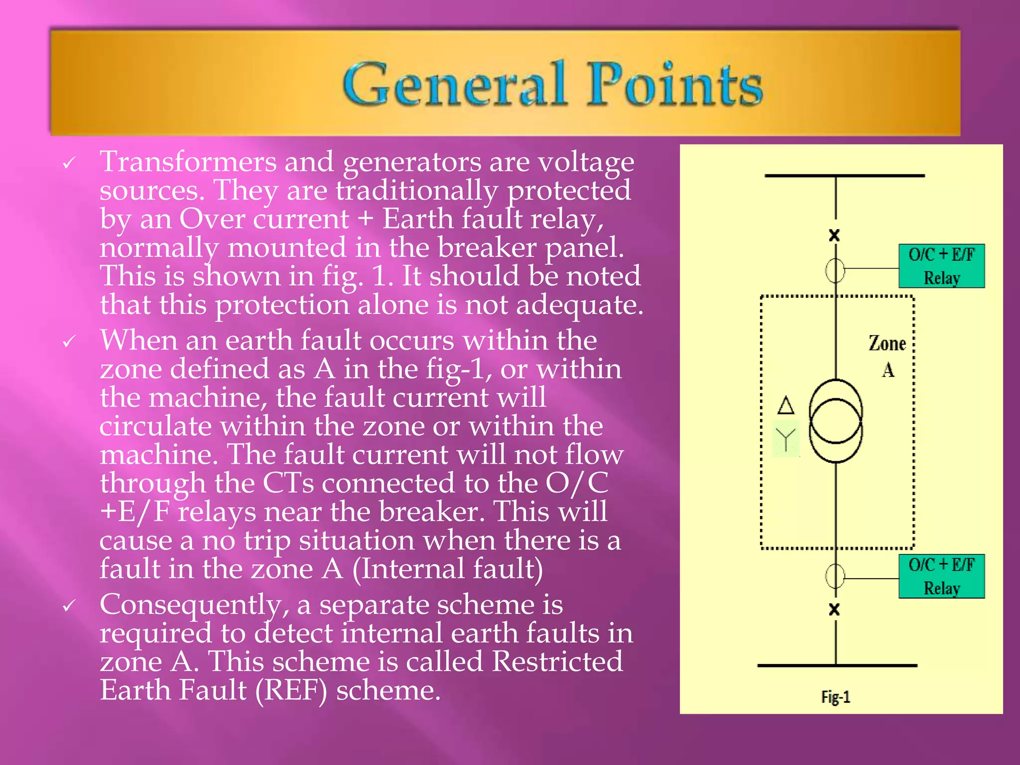
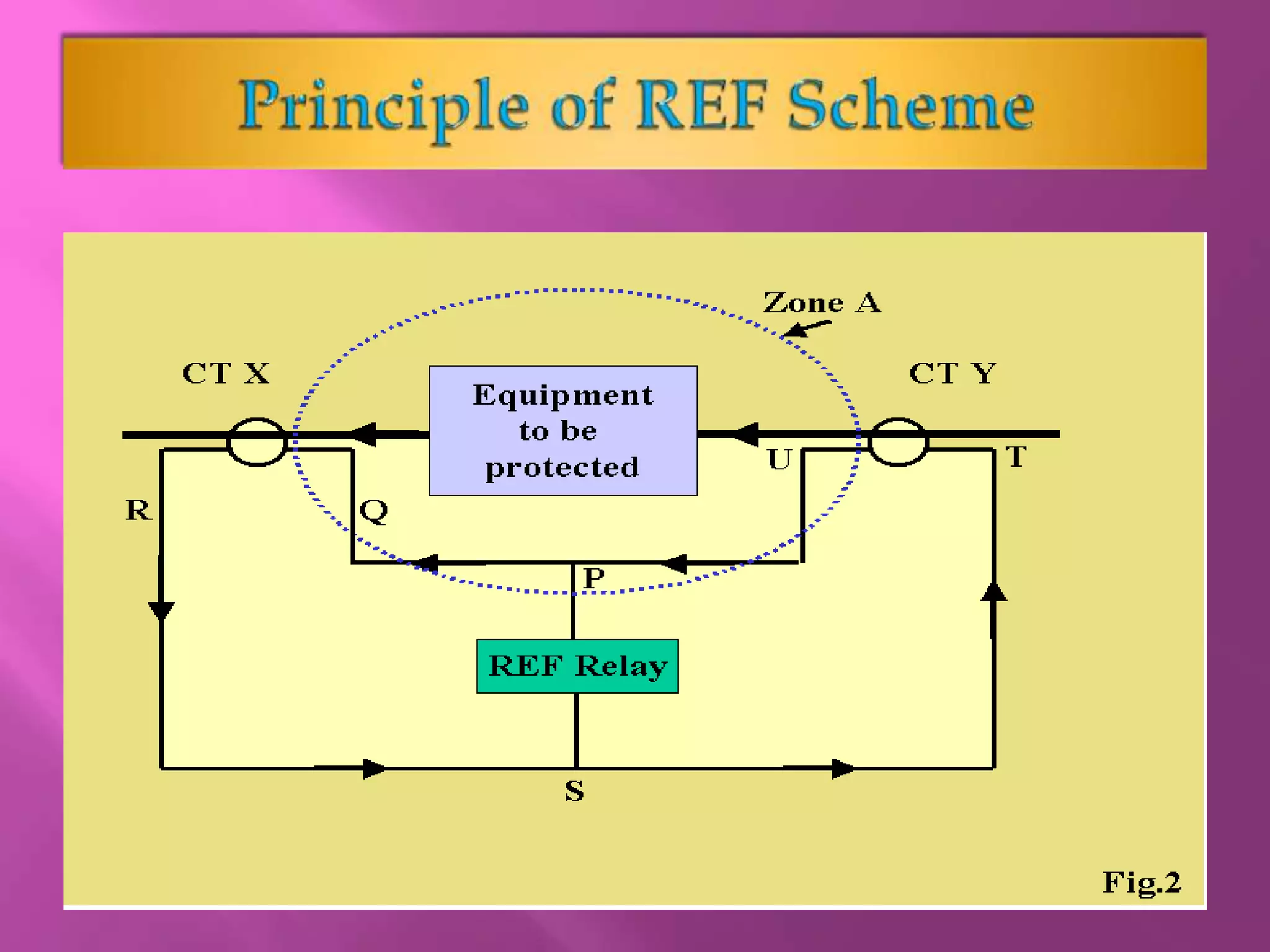
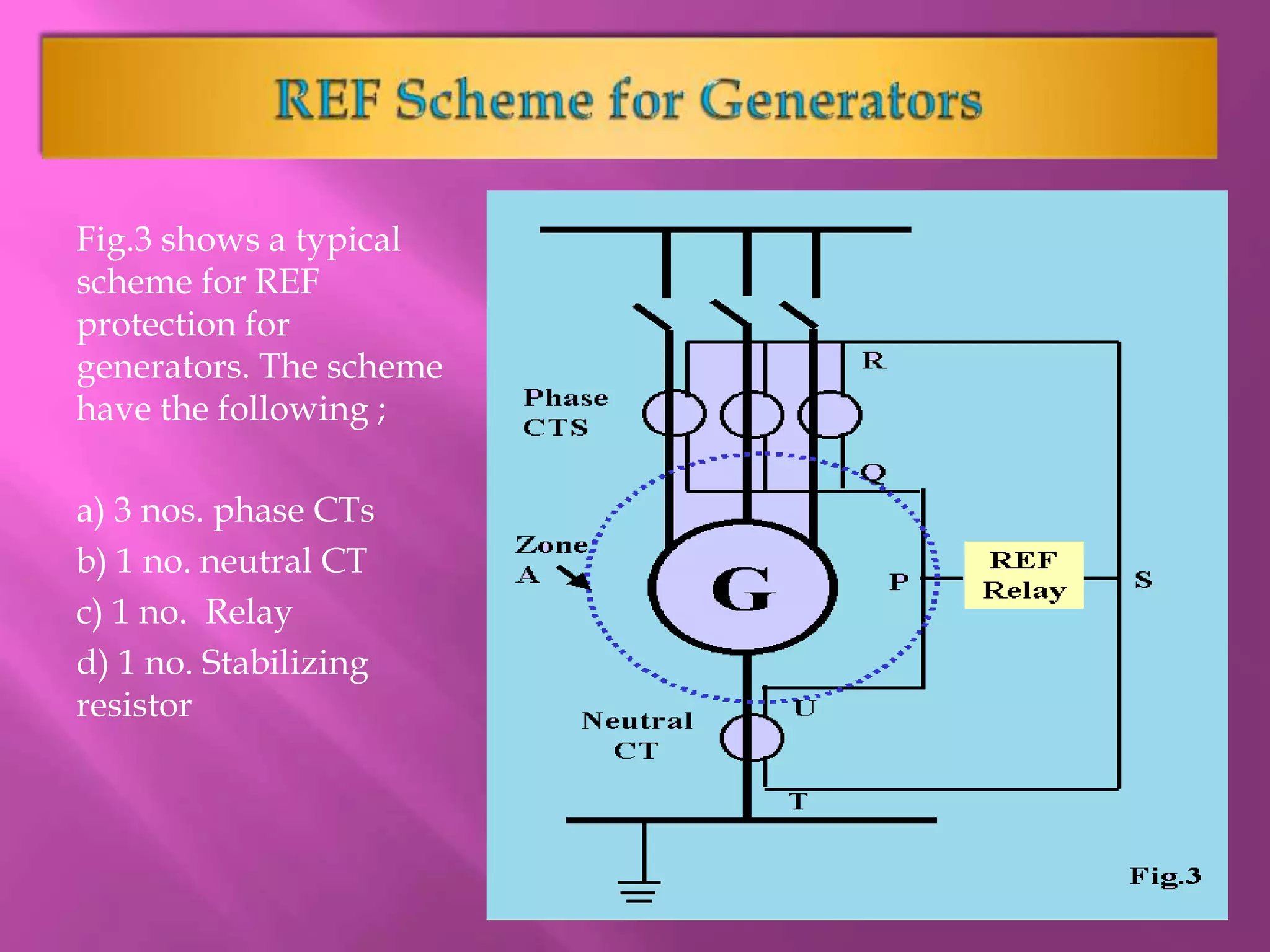
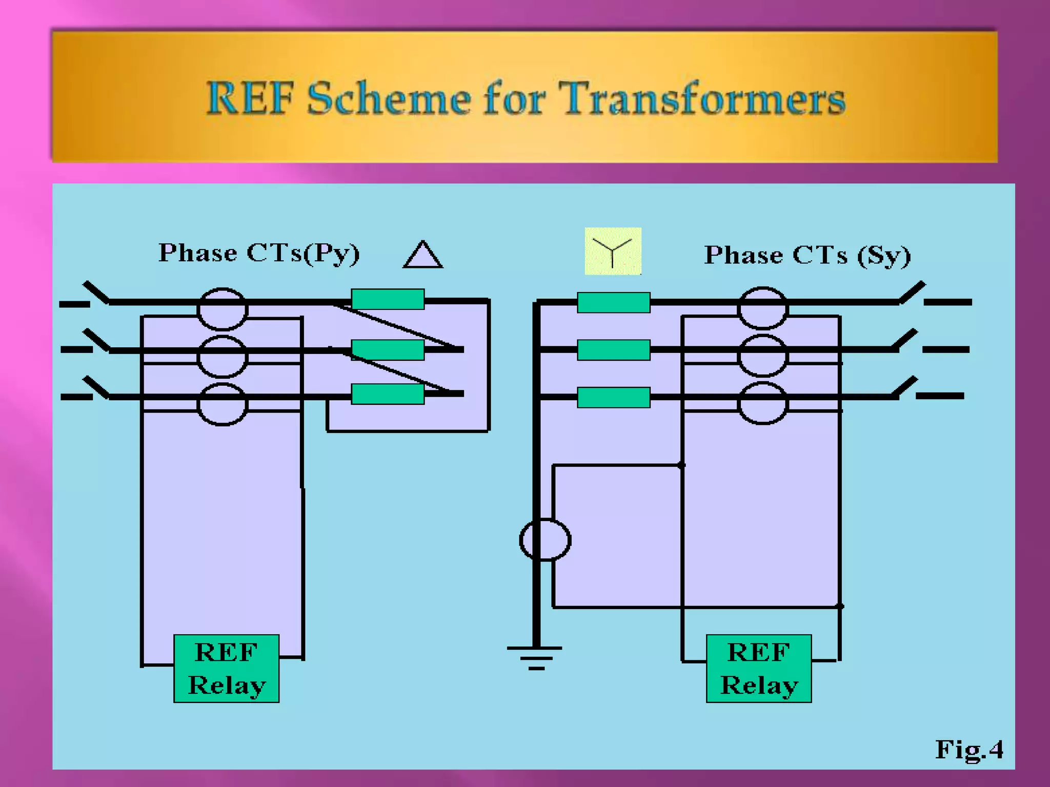
Presentation by RAMESH.G
 Transformers and generators are voltage
sources. They are traditionally protected
by an Over current + Earth fault relay,
normally mounted in the breaker panel.
This is shown in fig. 1. It should be noted
that this protection alone is not adequate.
 When an earth fault occurs within the
zone defined as A in the fig-1, or within
the machine, the fault current will
circulate within the zone or within the
machine. The fault current will not flow
through the CTs connected to the O/C
+E/F relays near the breaker. This will
cause a no trip situation when there is a
fault in the zone A (Internal fault)
 Consequently, a separate scheme is
required to detect internal earth faults in
zone A. This scheme is called Restricted
Earth Fault (REF) scheme.
 It should be noted that the fault currents in
Zone A is limited by the impedance of the
equipments in the zone.
 for transformers and generators it is very low
so the fault currents can rise very fast and
damage the equipment. Consequently REF
protection is of utmost importance for
generators and transformers.
 The name Restricted is derived – since the
objective of the protection is to detect the earth
fault in the specific zone , restricted to the zone,
starting from the breaker to the machine
terminals.
 In case of a generator, the machine terminal is
the neutral point.
 In case of a transformer , the machine terminal
becomes the star point of either the primary or
secondary winding or both. In case of delta
winding, it is the winding itself.
 It is well established that the sum of currents at
the beginning of the zone A should be equal to
the sum of currents exiting the zone .
 Two sets of CT’s are Used to derive this sum of
currents at the inlet and exit. A fault in the
zone will result in a difference in current.
 An over current relay is used to measure the
difference in the sum of these currents.
 Typical REF scheme shown in Fig-2.
 The REF relay is connected between P & S. It
will pick up if there is enough voltage across P-
S to drive the pick up current through the
relay.
 There are two current sources in the CT
secondary circuit PQRSTU:
a) The current produces by CT X (loop RSPQ)
b) The current produced by CT Y (loop UPST)
 Under normal conditions, vectorial sum of the
currents of these two CT’s will be equal and
opposite in the branch P-S (i.e.) the resultant
current in the branch PS will be zero.
 In this situation, the currents of CT X and CT Y
will circulate in the loop PQRSTU. The voltage
across P-S will be zero.
 When there is an earth fault within the zone A, the
currents of X & Y CT’s will not be equal, a small
difference of current will flow in the branch P-S.
This current will result in a voltage across P-S
since the current flows through the relay
impedance.
 If this voltage is adequate to operate the relay, the
relay will pick up this detecting a fault within the
zone.
 For a fault outside the zone, the currents
through CT’s X & Y will be the same so the
resultant current through P-S will still be zero
and the relay will not pick up.
 In this case the fault has to be cleared by
another O/C + E/F relay connected near the
breaker.
 REF relay will detect a fault within a zone restricted
between two CT’s and it will not detect a fault out side
the zone defined by the CT’s. This is true, only for ideal
conditions, where the two CT’s are perfectly matched.
 Following miss matches will occur under practical
situations in the field:
i) The CT secondary impedances may not be equal.
ii) The lead wires connecting the CT secondary's to the
relay may not have equal resistances.
iii) The CT’s may have different ratio error and phase
angle error due to this, the secondary current’s will not
be equal even if the primary currents are same.
iv) The CT’s may have different ratio error and phase
angle error due to this, the secondary current’s will not
be equal even if the primary currents are same.
 The cumulative effect all the above, can make the relay
trip even when there is a full load current flowing in
the primaries, though the primary side currents are
same, the secondary side currents need not be the same
so a voltage sufficient to trip the REF relay may
develop across P-S and hence the relay will trip.
 To make the relay insensitive to this voltage produced
by CT mismatch, a resistor is added in series with the
relay.
 Once this resistor is added, the relay will need a
voltage which is higher than the voltage produced by
the CT mismatch.
 This resistor is called stabilizing resistor ,this is an
important component in REF scheme since this ensures
stability in the scheme by avoiding spurious tripping.
 It should be noted that actual input circuit to trip
mechanism (consisting of the Relay + stabilizing
resistor) has become a high impedance circuit.
 If the relay Has to trip, the CT secondary's
should produce sufficiently high enough Voltage
to activate the relay, after allowing for the drop
across the stabilizing Resistor.
 To ensure the CT’s produce enough voltage, an
additional specification the Knee point voltage is
included for the CT’s used for REF protection.
 Knee point voltage (KPV) is defined as the point
on the magnetizing curve (of the material used
for the CT core) where the core will need 50%
increase in the magnetizing force (ampere turns)
to cause a 10% increase in the flux Density.
(Voltage builds up across secondary).
 In effect, KPV defines the end of the linear portion
of the BH curve. Higher the KPV, larger is the
linear zone and better will be secondary output for
higher fault currents. Higher the KPV, better are
the chances of a high impedance relay trip.
Fig.3 shows a typical
scheme for REF
protection for
generators. The scheme
have the following ;
a) 3 nos. phase CTs
b) 1 no. neutral CT
c) 1 no. Relay
d) 1 no. Stabilizing
resistor
 Fig.4 shows a typical scheme for REF protection for
transformers. It should be noted that transformers will
need two REF schemes ,one on the primary side and
the other on the secondary side.
 For the transformer primary side , which is usually
delta connected, followings are in the REF scheme:
a) 3 nos. phase CTs
b) 1 no. Relay
d) 1 no. Stabilizing resistor
 For the transformer secondary side, which is usually
star connected, followings are in the REF scheme:
a) 3 nos. phase CTs
b) 1 no. neutral CT
c) 1 no. Relay
d) 1 no. Stabilizing resistor
Restricted Earth Fault(REF) Protection.pptx

Restricted Earth Fault(REF) Protection.pptx

  • 1.
  • 2.
     Transformers andgenerators are voltage sources. They are traditionally protected by an Over current + Earth fault relay, normally mounted in the breaker panel. This is shown in fig. 1. It should be noted that this protection alone is not adequate.  When an earth fault occurs within the zone defined as A in the fig-1, or within the machine, the fault current will circulate within the zone or within the machine. The fault current will not flow through the CTs connected to the O/C +E/F relays near the breaker. This will cause a no trip situation when there is a fault in the zone A (Internal fault)  Consequently, a separate scheme is required to detect internal earth faults in zone A. This scheme is called Restricted Earth Fault (REF) scheme.
  • 3.
     It shouldbe noted that the fault currents in Zone A is limited by the impedance of the equipments in the zone.  for transformers and generators it is very low so the fault currents can rise very fast and damage the equipment. Consequently REF protection is of utmost importance for generators and transformers.
  • 4.
     The nameRestricted is derived – since the objective of the protection is to detect the earth fault in the specific zone , restricted to the zone, starting from the breaker to the machine terminals.  In case of a generator, the machine terminal is the neutral point.  In case of a transformer , the machine terminal becomes the star point of either the primary or secondary winding or both. In case of delta winding, it is the winding itself.
  • 5.
     It iswell established that the sum of currents at the beginning of the zone A should be equal to the sum of currents exiting the zone .  Two sets of CT’s are Used to derive this sum of currents at the inlet and exit. A fault in the zone will result in a difference in current.  An over current relay is used to measure the difference in the sum of these currents.
  • 7.
     Typical REFscheme shown in Fig-2.  The REF relay is connected between P & S. It will pick up if there is enough voltage across P- S to drive the pick up current through the relay.  There are two current sources in the CT secondary circuit PQRSTU: a) The current produces by CT X (loop RSPQ) b) The current produced by CT Y (loop UPST)
  • 8.
     Under normalconditions, vectorial sum of the currents of these two CT’s will be equal and opposite in the branch P-S (i.e.) the resultant current in the branch PS will be zero.  In this situation, the currents of CT X and CT Y will circulate in the loop PQRSTU. The voltage across P-S will be zero.  When there is an earth fault within the zone A, the currents of X & Y CT’s will not be equal, a small difference of current will flow in the branch P-S. This current will result in a voltage across P-S since the current flows through the relay impedance.  If this voltage is adequate to operate the relay, the relay will pick up this detecting a fault within the zone.
  • 9.
     For afault outside the zone, the currents through CT’s X & Y will be the same so the resultant current through P-S will still be zero and the relay will not pick up.  In this case the fault has to be cleared by another O/C + E/F relay connected near the breaker.
  • 10.
     REF relaywill detect a fault within a zone restricted between two CT’s and it will not detect a fault out side the zone defined by the CT’s. This is true, only for ideal conditions, where the two CT’s are perfectly matched.  Following miss matches will occur under practical situations in the field: i) The CT secondary impedances may not be equal. ii) The lead wires connecting the CT secondary's to the relay may not have equal resistances. iii) The CT’s may have different ratio error and phase angle error due to this, the secondary current’s will not be equal even if the primary currents are same. iv) The CT’s may have different ratio error and phase angle error due to this, the secondary current’s will not be equal even if the primary currents are same.
  • 11.
     The cumulativeeffect all the above, can make the relay trip even when there is a full load current flowing in the primaries, though the primary side currents are same, the secondary side currents need not be the same so a voltage sufficient to trip the REF relay may develop across P-S and hence the relay will trip.  To make the relay insensitive to this voltage produced by CT mismatch, a resistor is added in series with the relay.  Once this resistor is added, the relay will need a voltage which is higher than the voltage produced by the CT mismatch.  This resistor is called stabilizing resistor ,this is an important component in REF scheme since this ensures stability in the scheme by avoiding spurious tripping.
  • 12.
     It shouldbe noted that actual input circuit to trip mechanism (consisting of the Relay + stabilizing resistor) has become a high impedance circuit.  If the relay Has to trip, the CT secondary's should produce sufficiently high enough Voltage to activate the relay, after allowing for the drop across the stabilizing Resistor.  To ensure the CT’s produce enough voltage, an additional specification the Knee point voltage is included for the CT’s used for REF protection.
  • 13.
     Knee pointvoltage (KPV) is defined as the point on the magnetizing curve (of the material used for the CT core) where the core will need 50% increase in the magnetizing force (ampere turns) to cause a 10% increase in the flux Density. (Voltage builds up across secondary).  In effect, KPV defines the end of the linear portion of the BH curve. Higher the KPV, larger is the linear zone and better will be secondary output for higher fault currents. Higher the KPV, better are the chances of a high impedance relay trip.
  • 14.
    Fig.3 shows atypical scheme for REF protection for generators. The scheme have the following ; a) 3 nos. phase CTs b) 1 no. neutral CT c) 1 no. Relay d) 1 no. Stabilizing resistor
  • 16.
     Fig.4 showsa typical scheme for REF protection for transformers. It should be noted that transformers will need two REF schemes ,one on the primary side and the other on the secondary side.  For the transformer primary side , which is usually delta connected, followings are in the REF scheme: a) 3 nos. phase CTs b) 1 no. Relay d) 1 no. Stabilizing resistor  For the transformer secondary side, which is usually star connected, followings are in the REF scheme: a) 3 nos. phase CTs b) 1 no. neutral CT c) 1 no. Relay d) 1 no. Stabilizing resistor