Downloaded 471 times
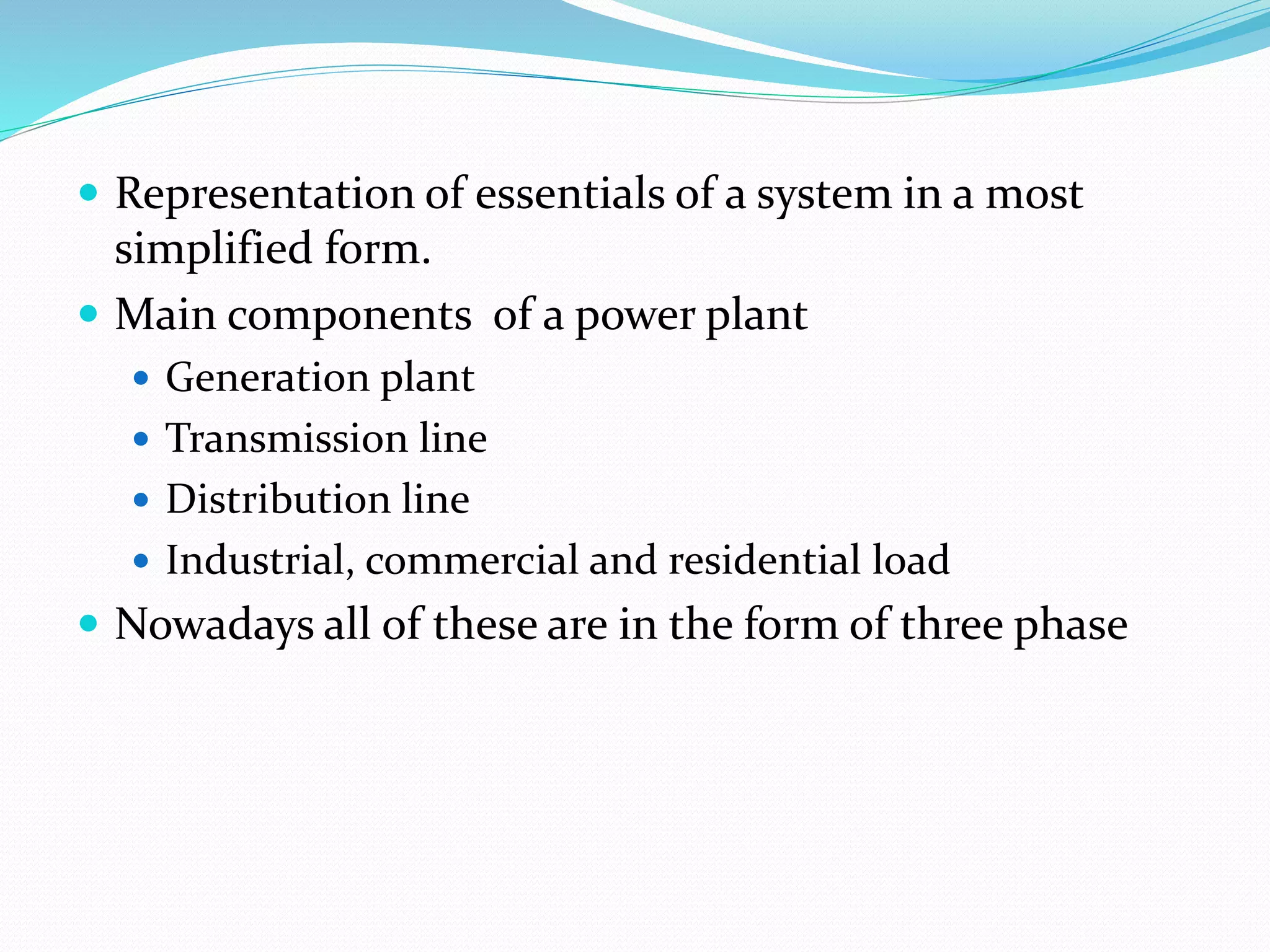
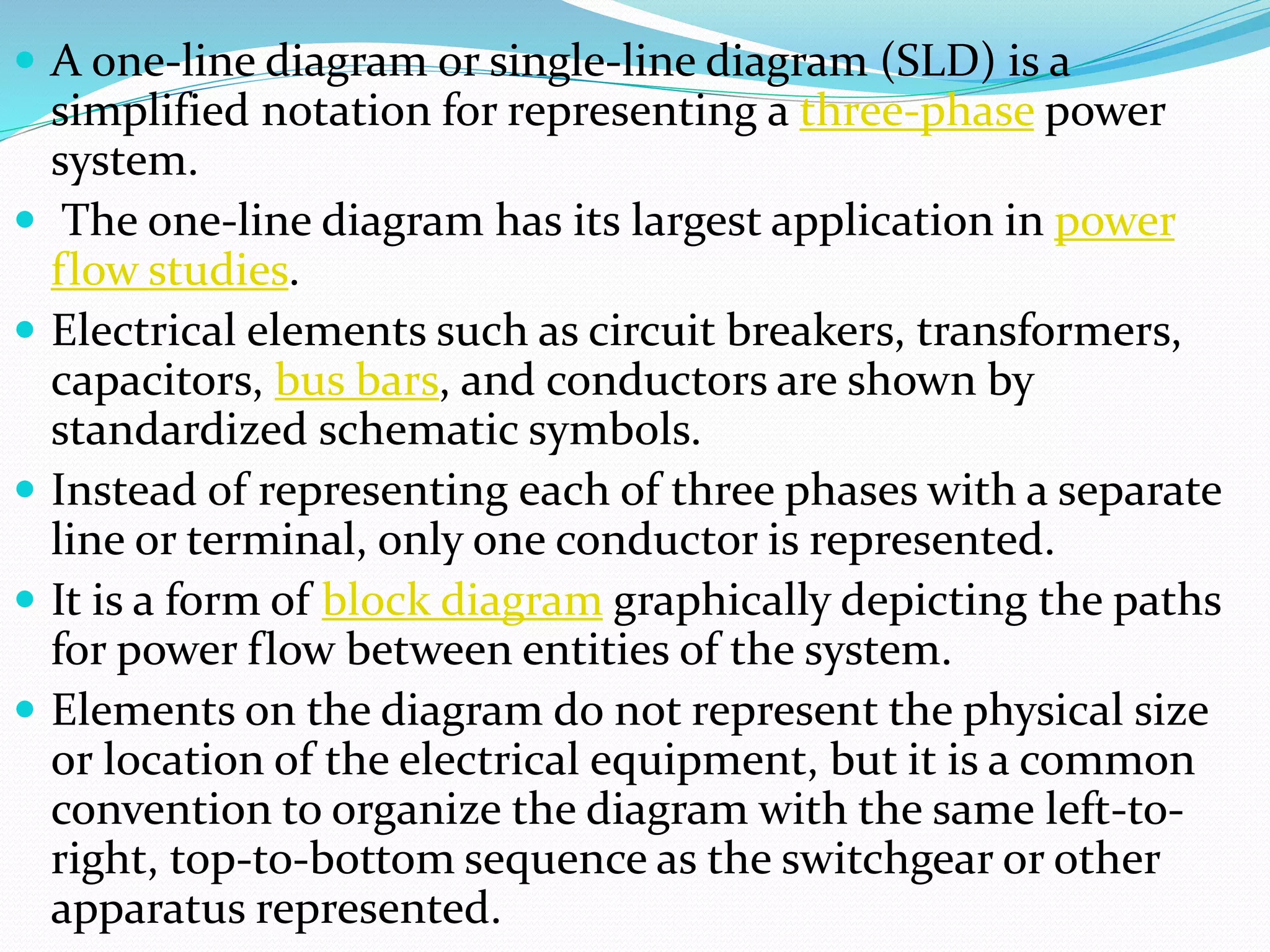
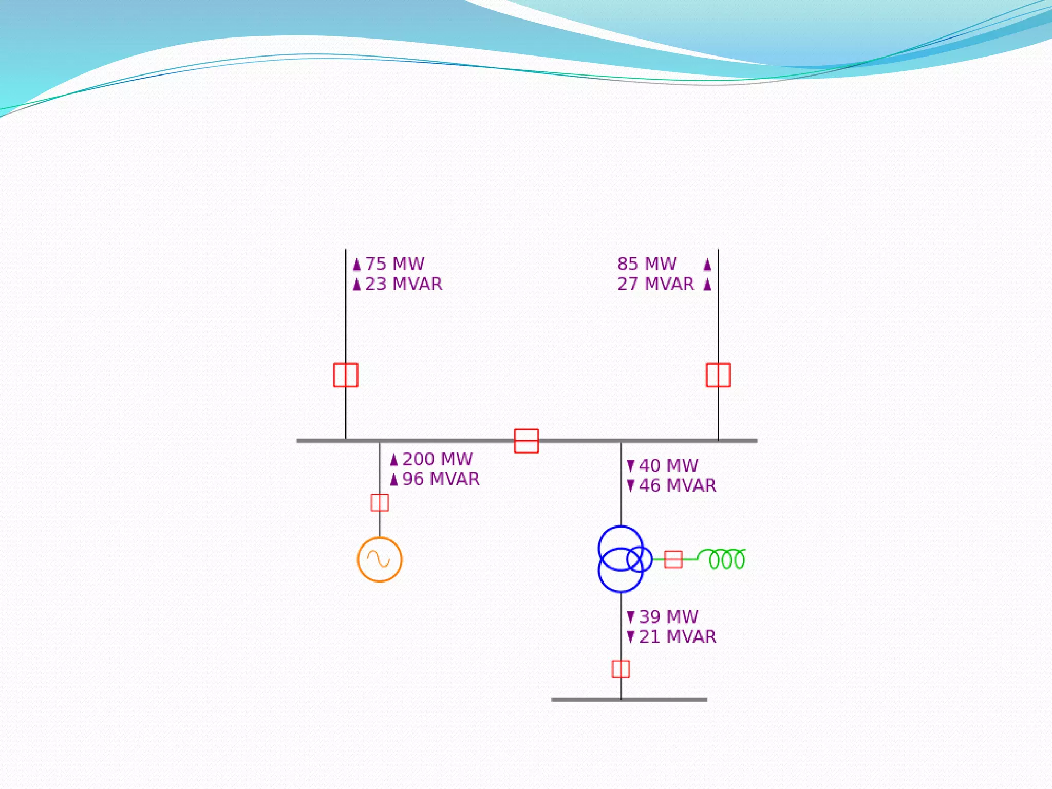
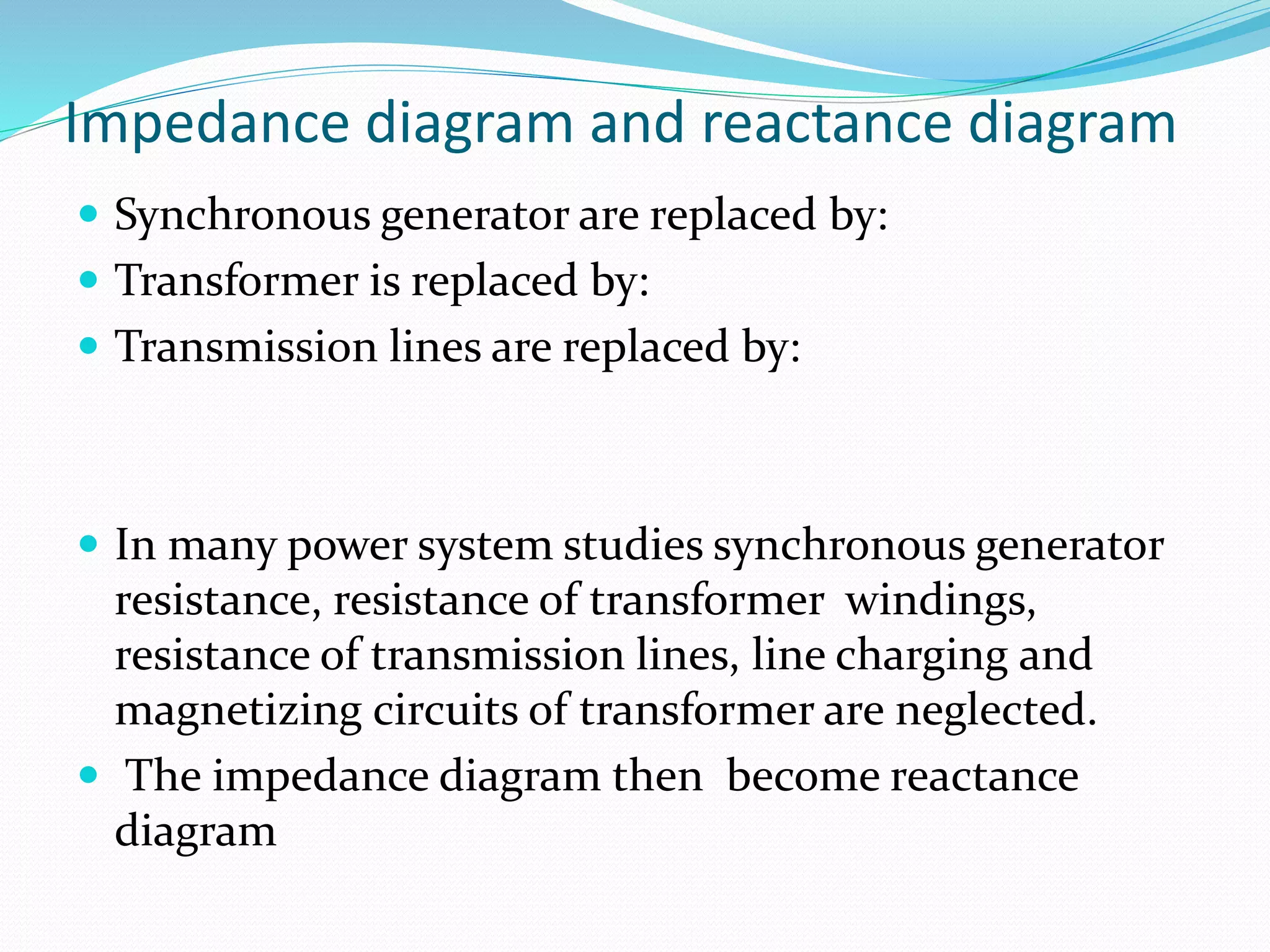
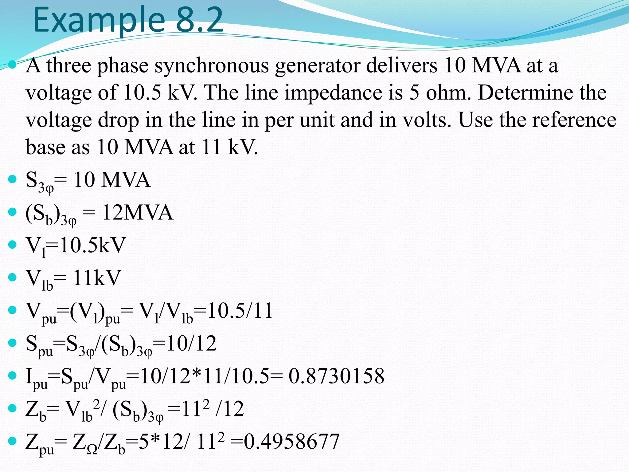
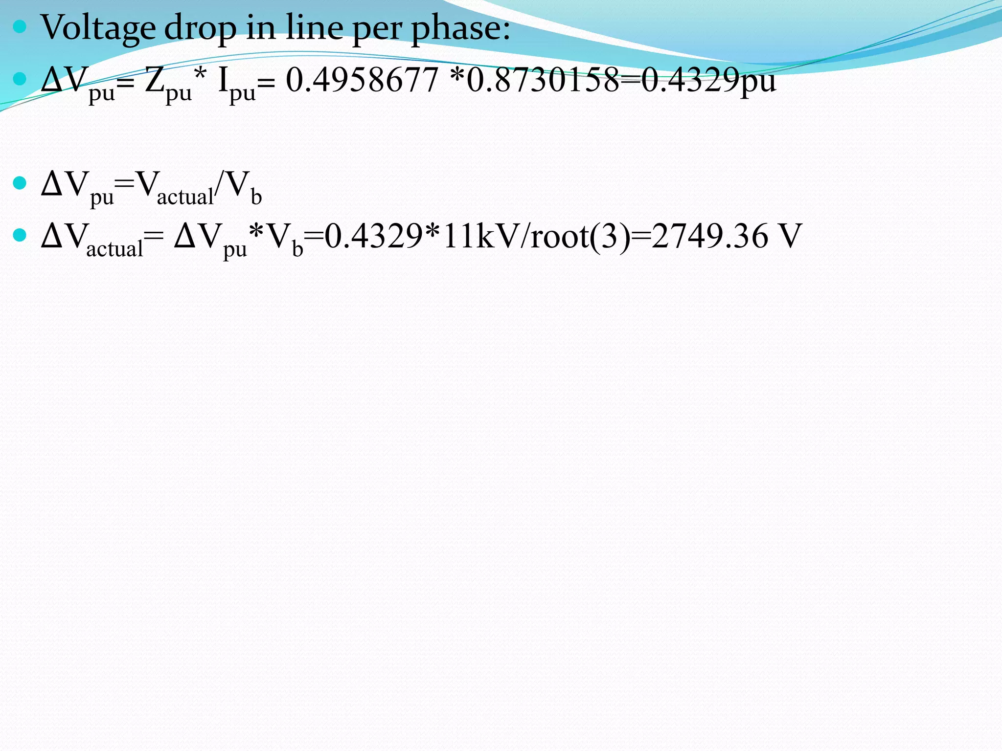

The document discusses one-line diagrams, which are simplified diagrams used in power systems to represent the essential components in a simplified graphical format. A one-line diagram shows the main components of a power system like generators, transmission lines, transformers, and loads using standardized symbols. It represents the paths of power flow through the system from generation to transmission to distribution. The diagram is structured to match the physical layout. Impedance and reactance diagrams are similar but represent electrical elements like generators and lines as impedance/reactance values instead of physical components. An example calculation of voltage drop in a transmission line is provided.


![Power system planning & operation [eceg 4410]](https://cdn.slidesharecdn.com/ss_thumbnails/powersystemplanningoperationeceg-4410-130607134359-phpapp01-thumbnail.jpg?width=640&height=640&fit=bounds)


![[LECTURE - 01 & 02] Equivalent Circuit P](https://cdn.slidesharecdn.com/ss_thumbnails/lec-0102equivalentcircuit-241104145204-d52809f3-thumbnail.jpg?width=640&height=640&fit=bounds)


