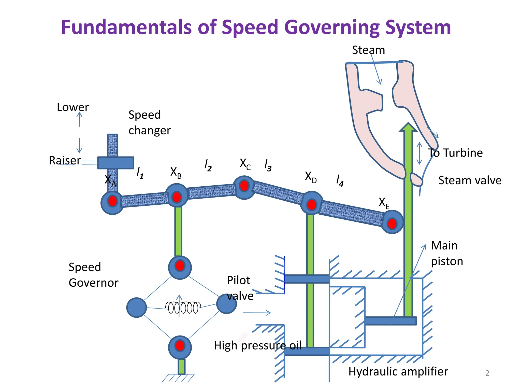
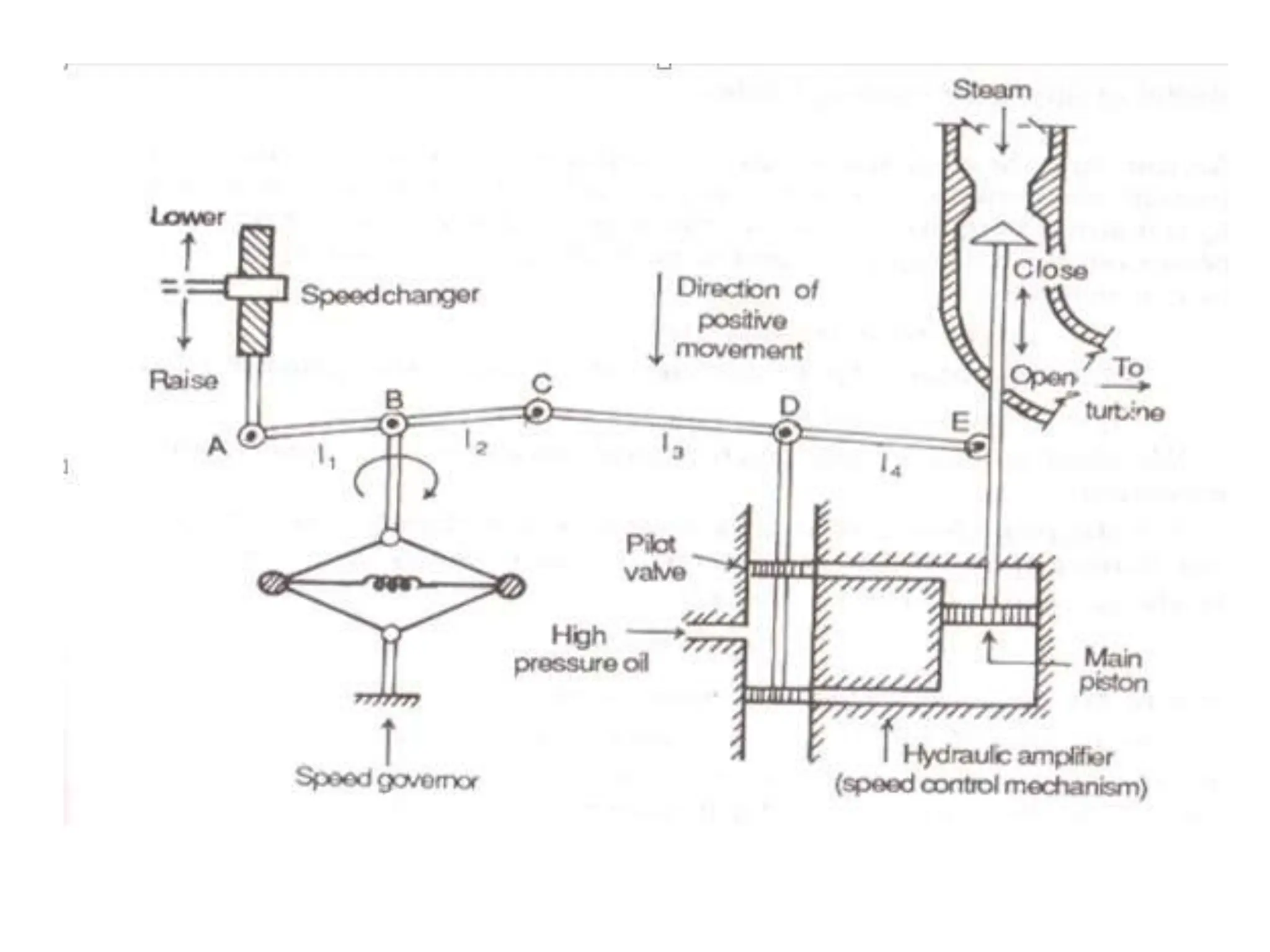
1. The document discusses load frequency control in single area and multi-area power systems. It covers modeling of speed governing systems, load-frequency control of a single area, and control of a two-area system.
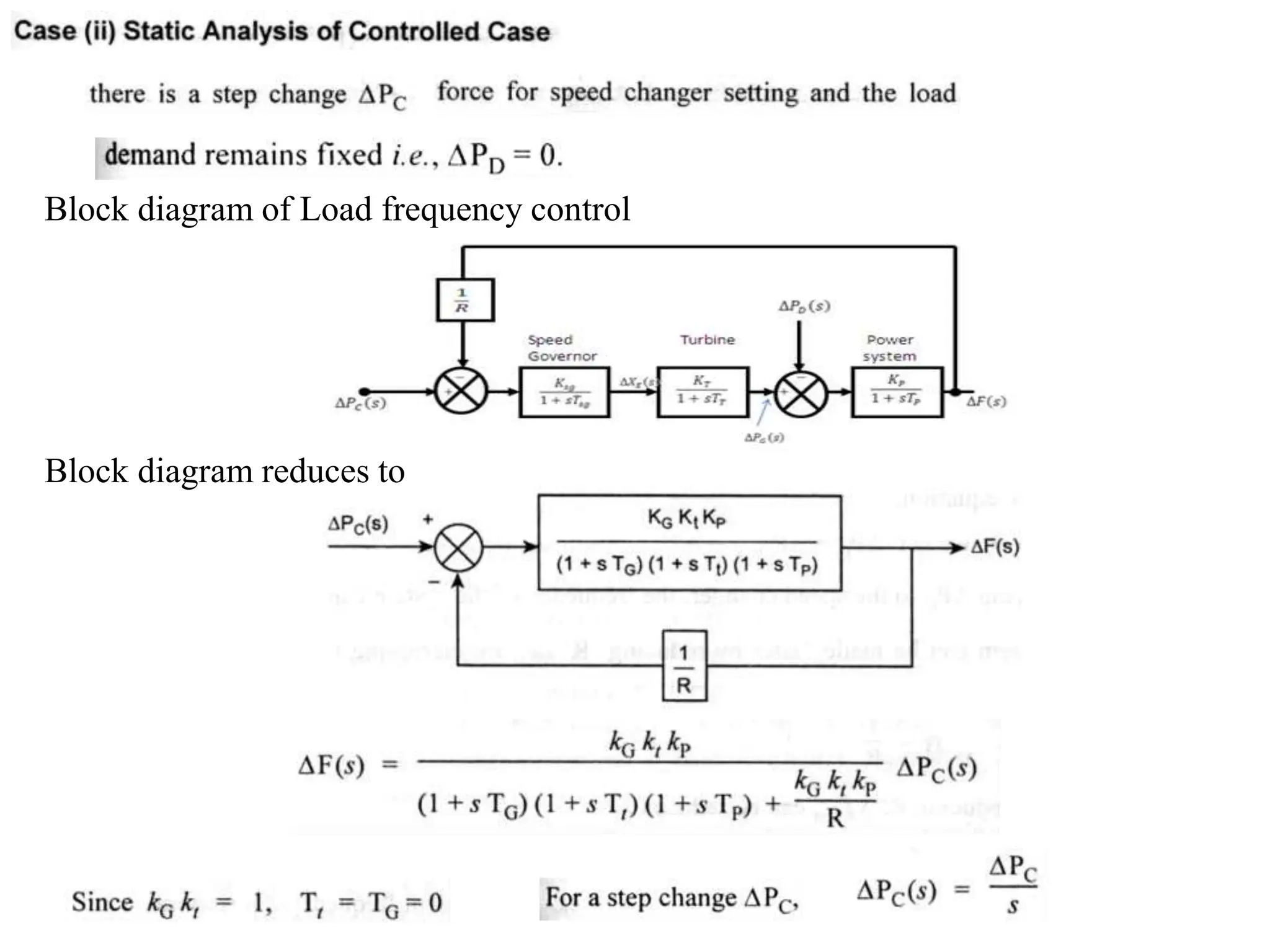
2. Key aspects covered include static and dynamic analysis of uncontrolled and controlled single area systems, modeling and analysis of a two-area system without and with tie-line bias control.
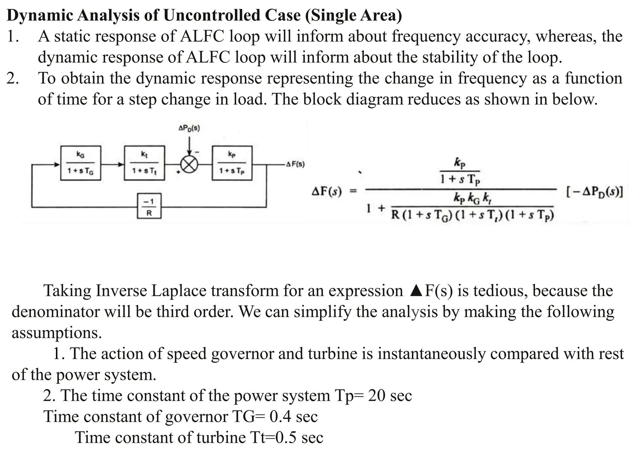
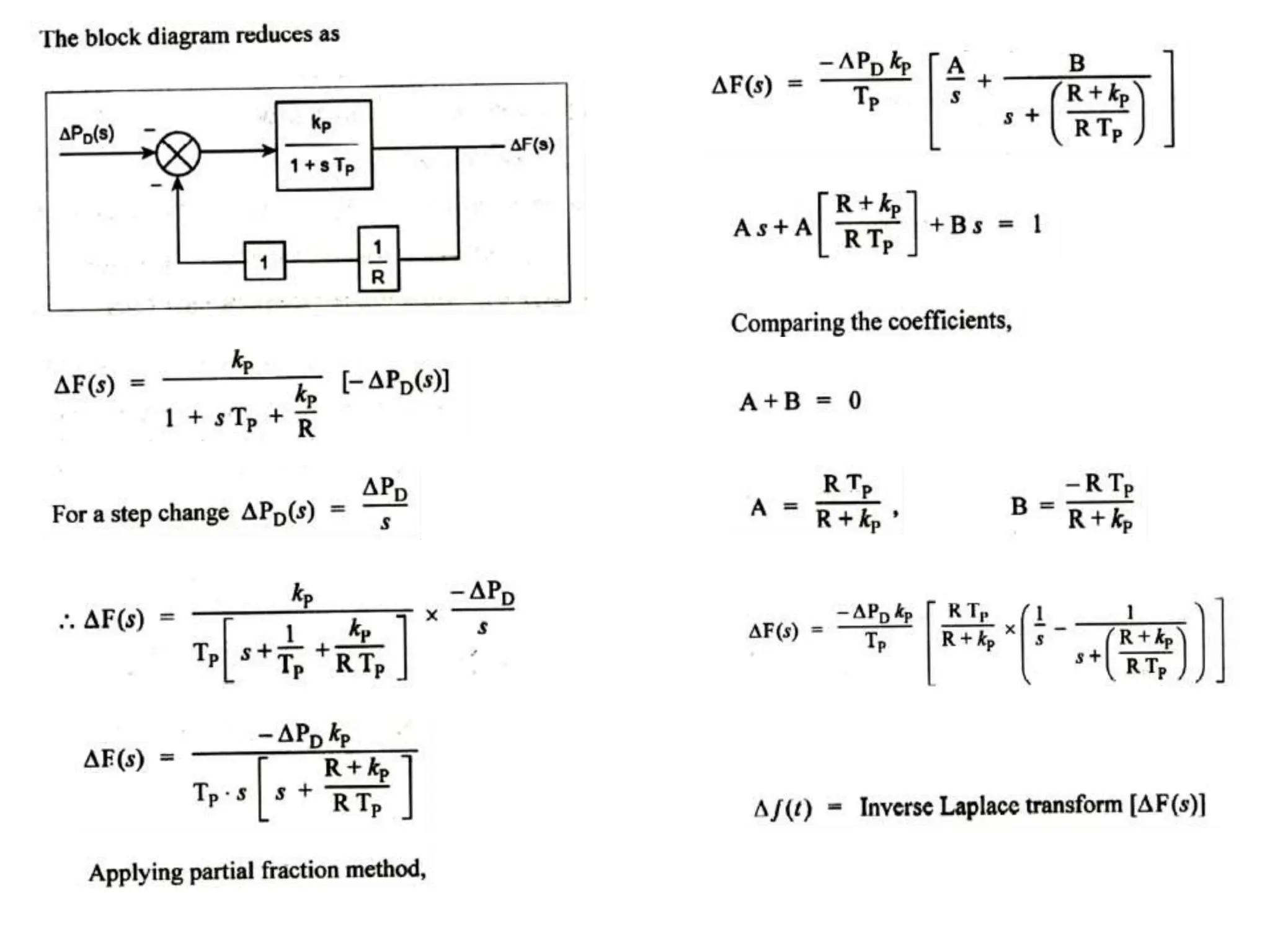
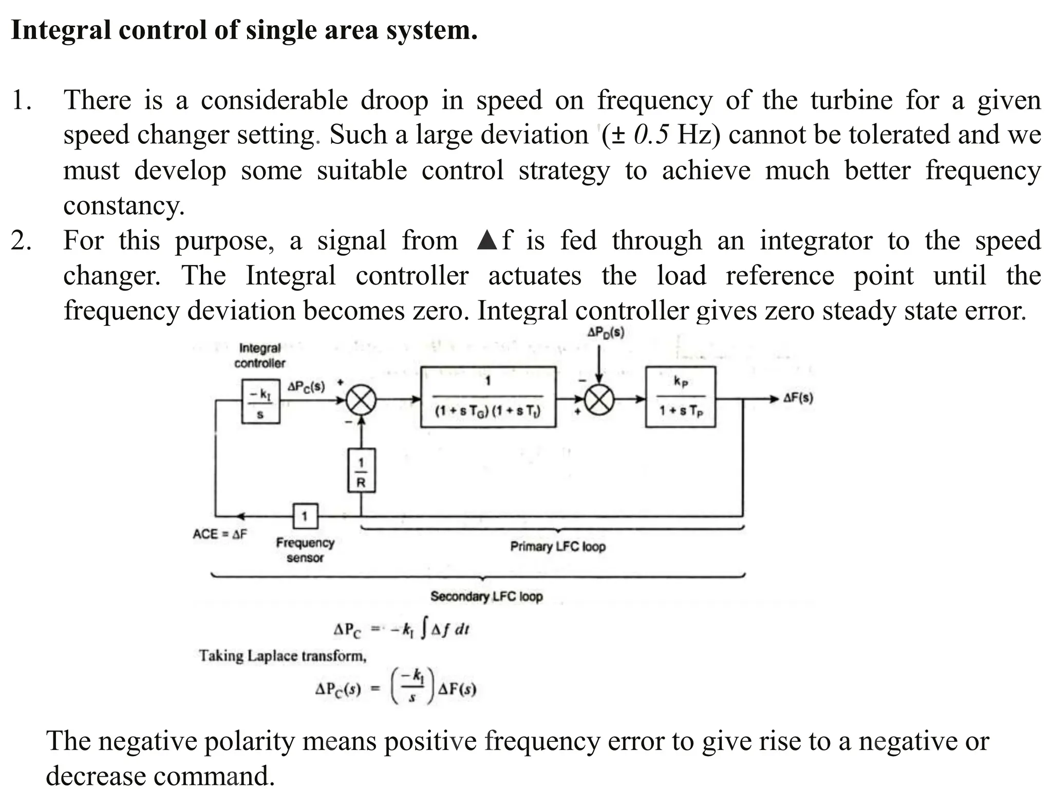
3. Integral control is introduced to eliminate the steady-state frequency error for a single area system. The dynamic response of the single area system is analyzed with and without integral control.


![Frequency_Control_in_Two_Area_Power_System_Integrating_ppt[1].pptx](https://cdn.slidesharecdn.com/ss_thumbnails/frequencycontrolintwoareapowersystemintegratingppt1-241111052857-fc615c94-thumbnail.jpg?width=640&height=640&fit=bounds)


