Downloaded 1,013 times


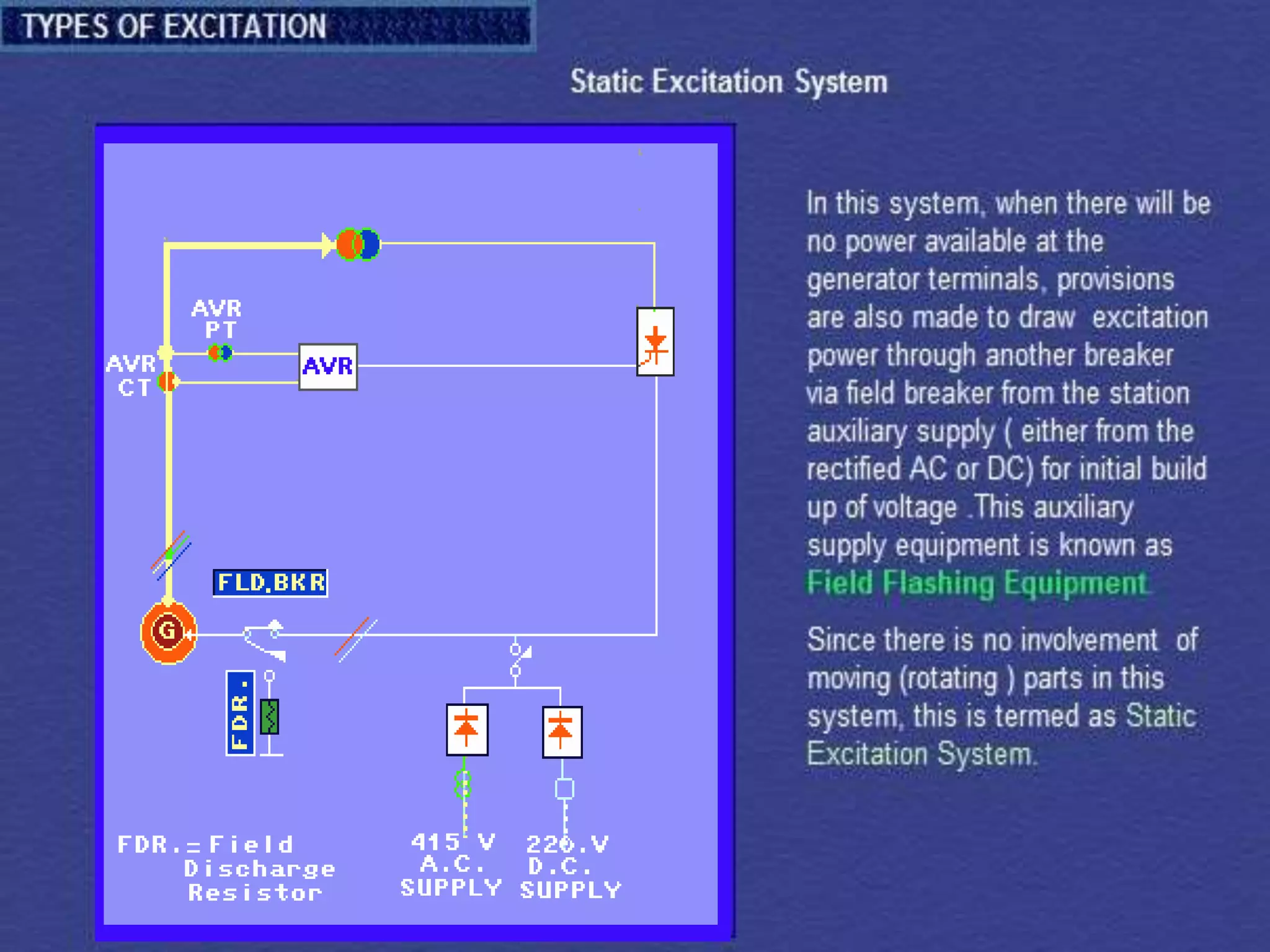
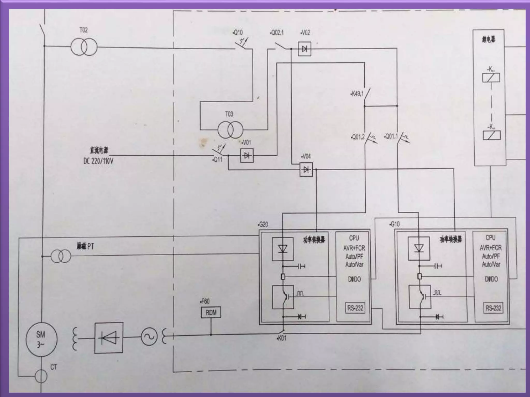
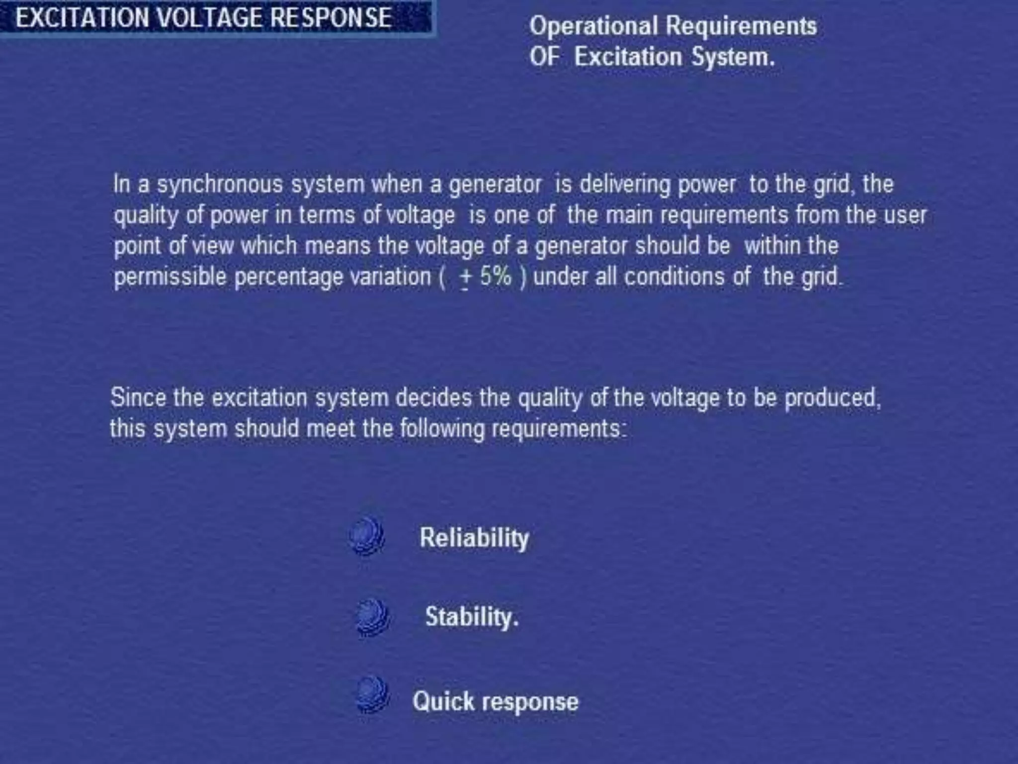
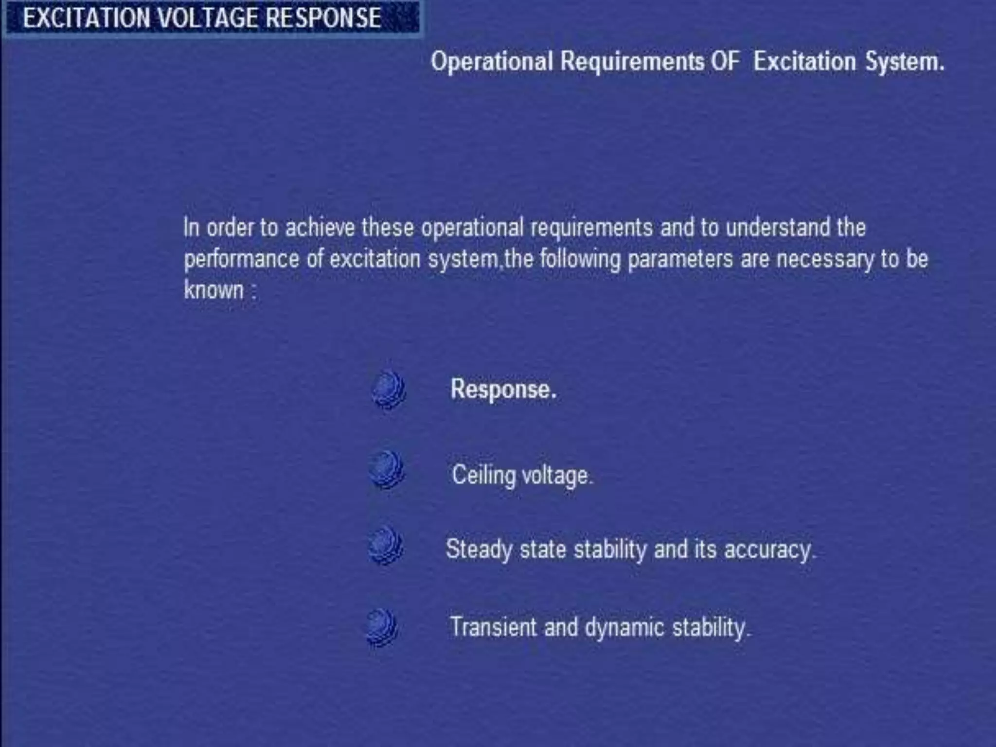
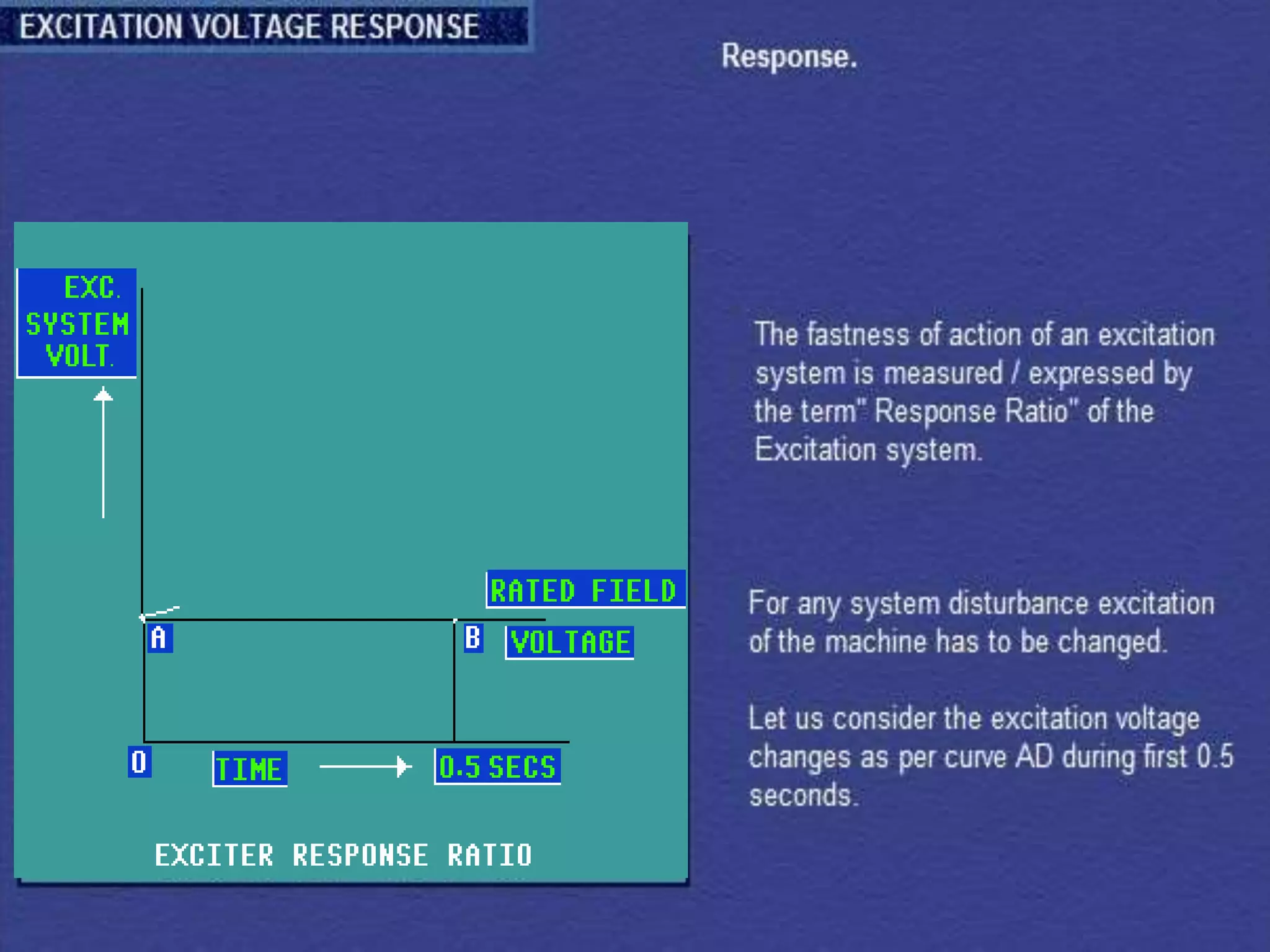
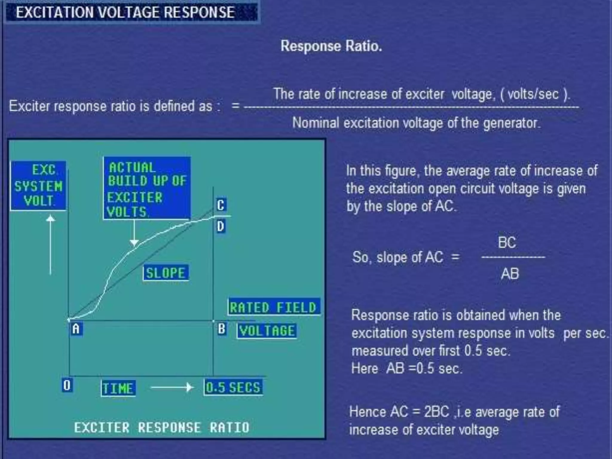
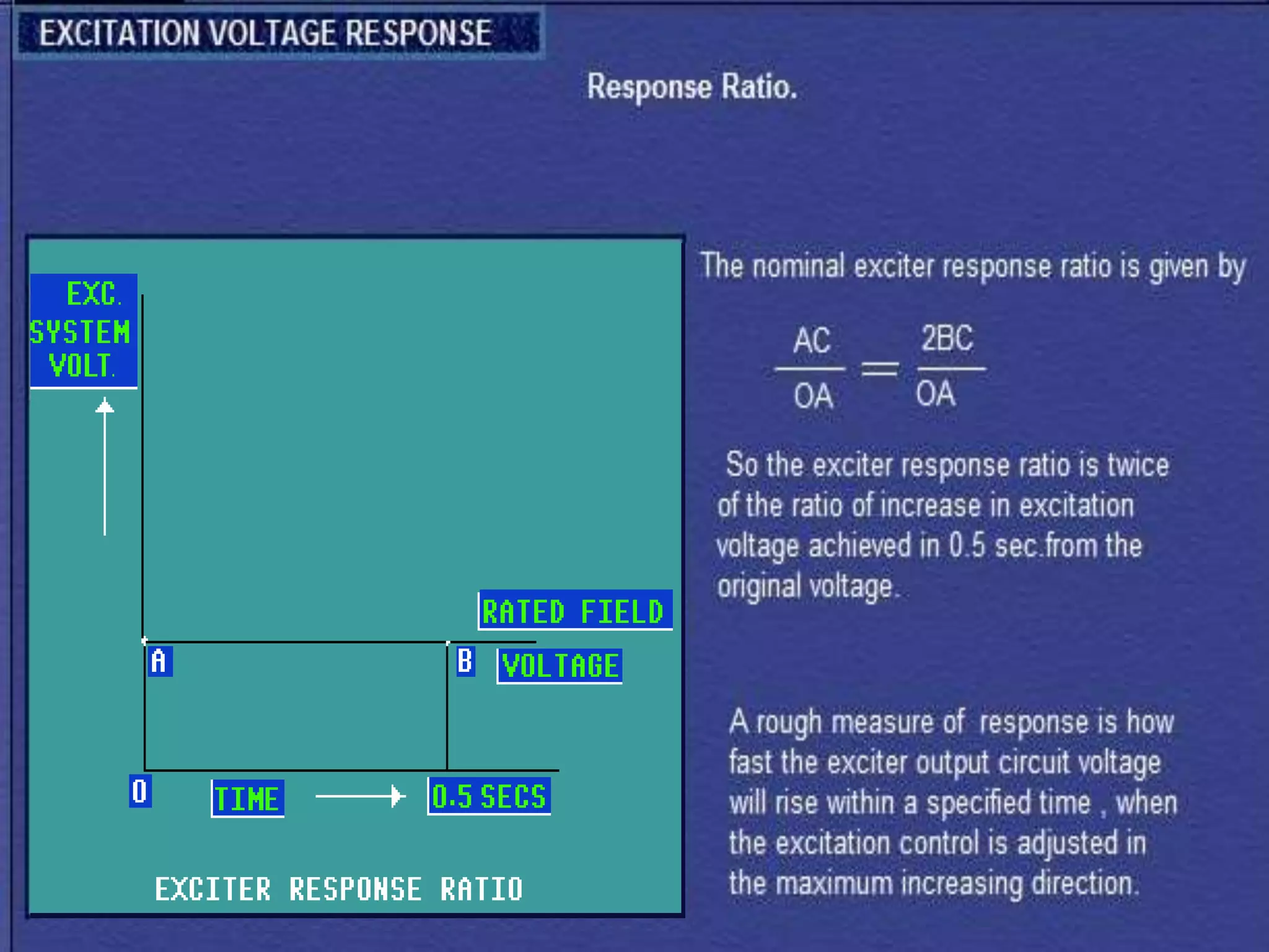
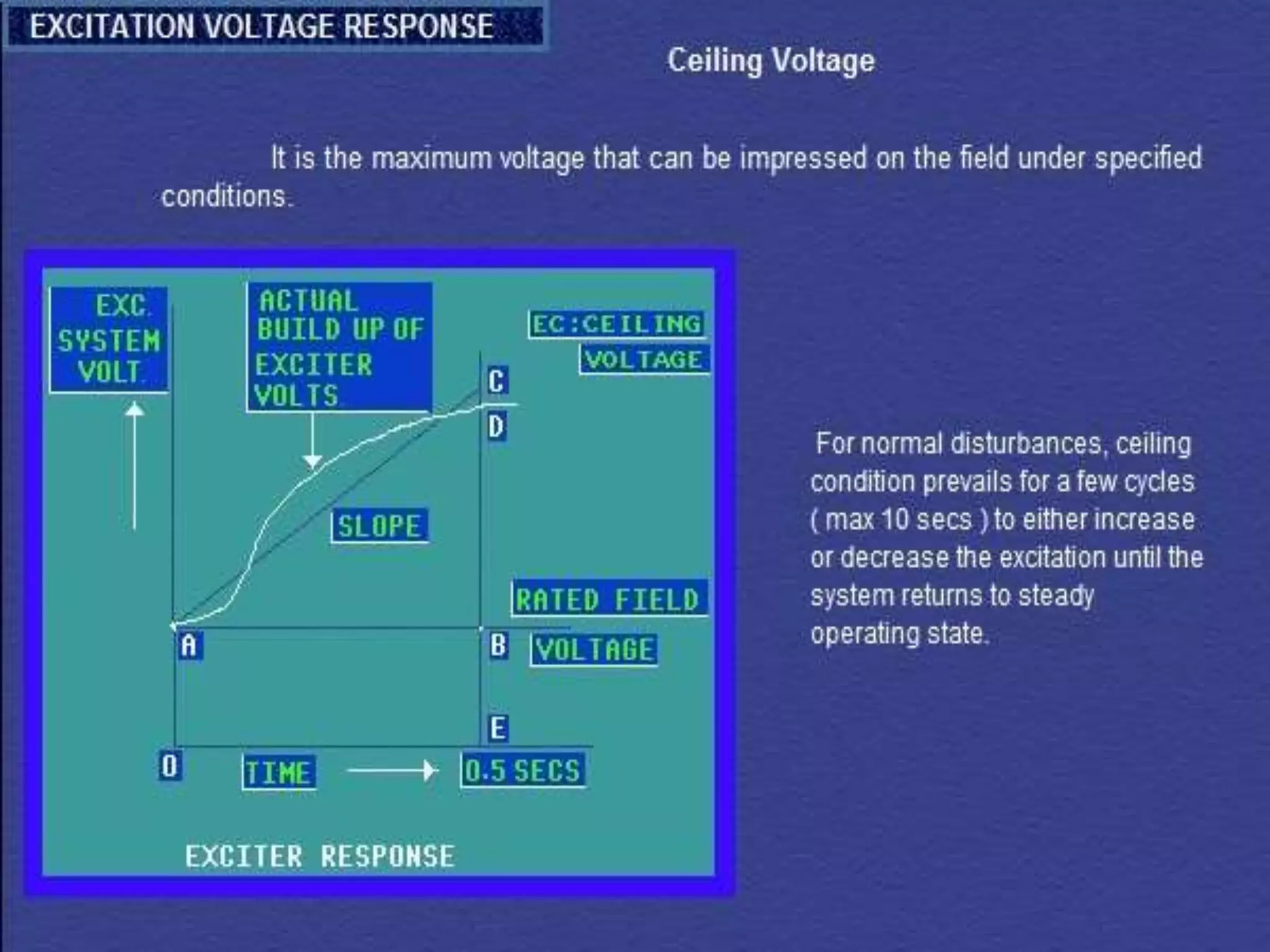
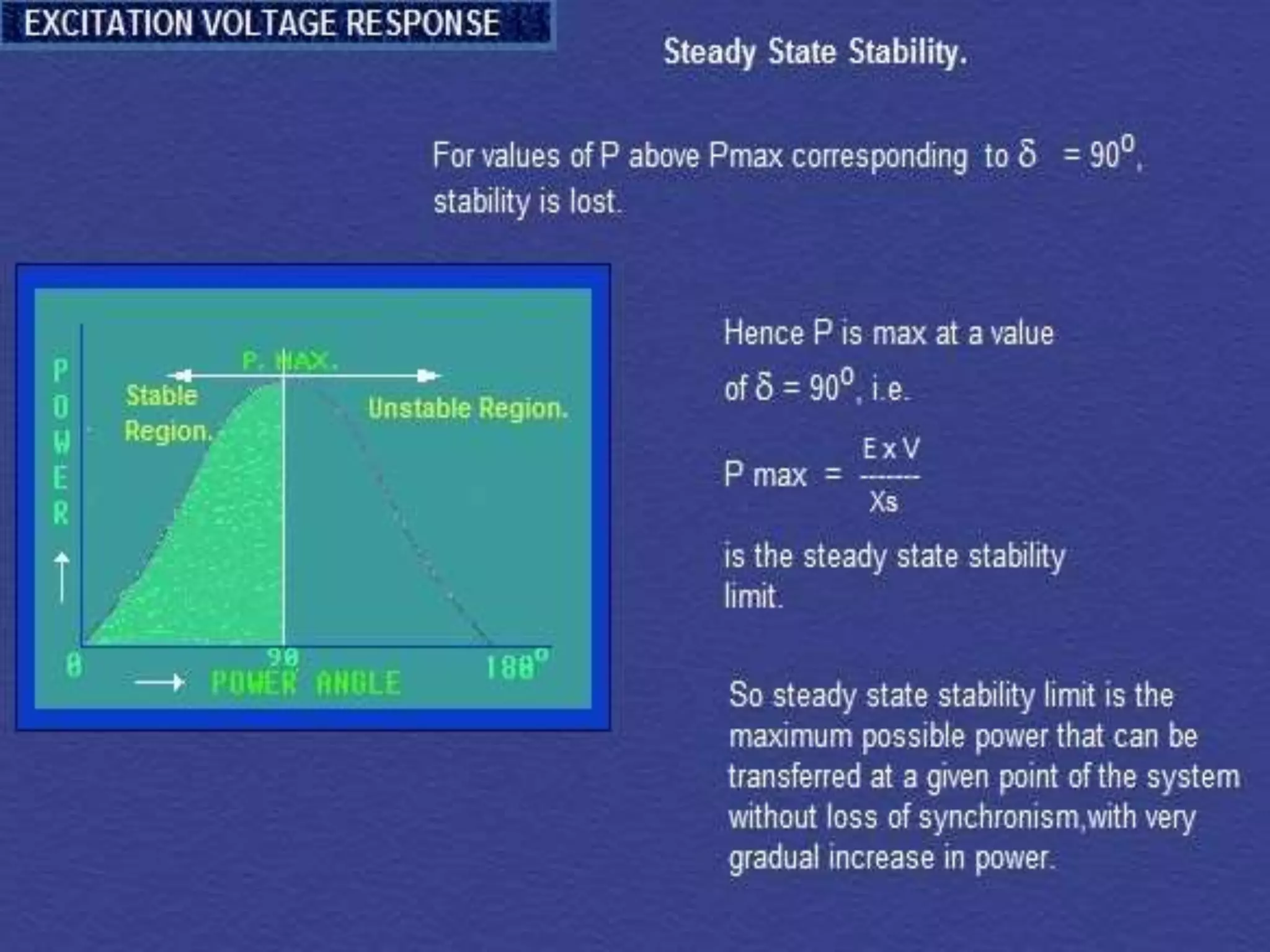
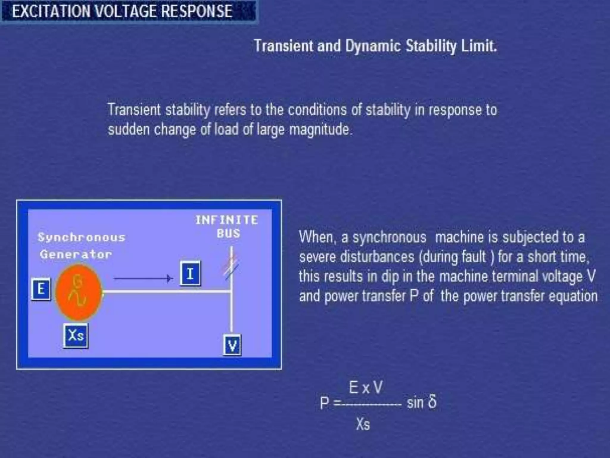
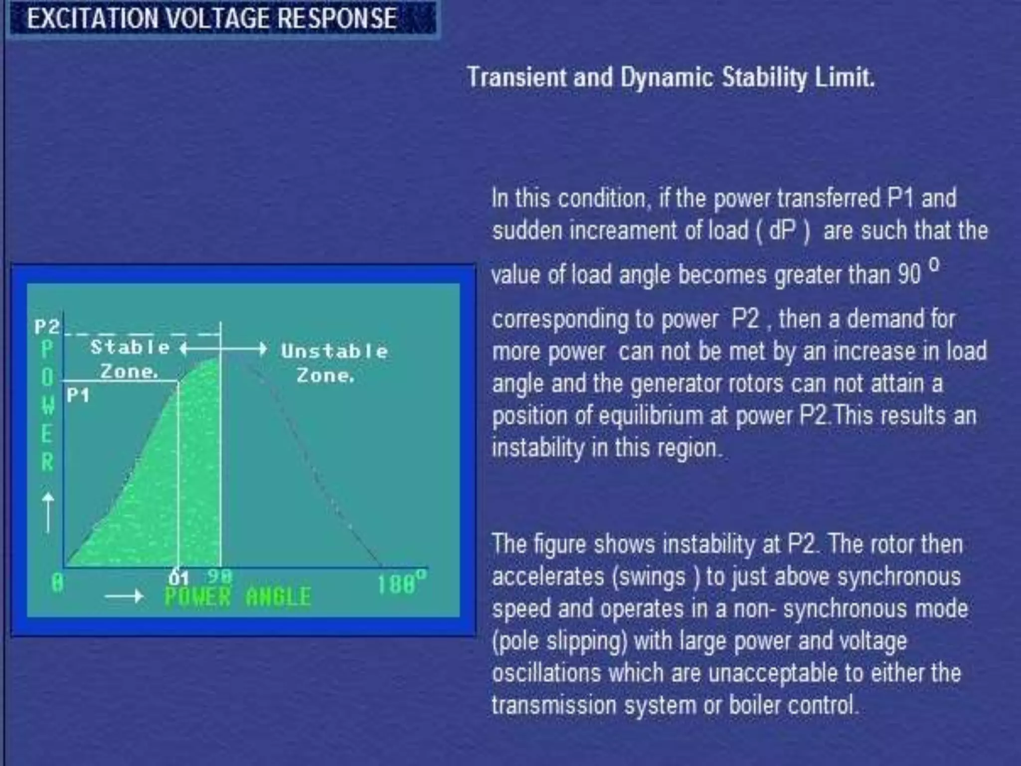
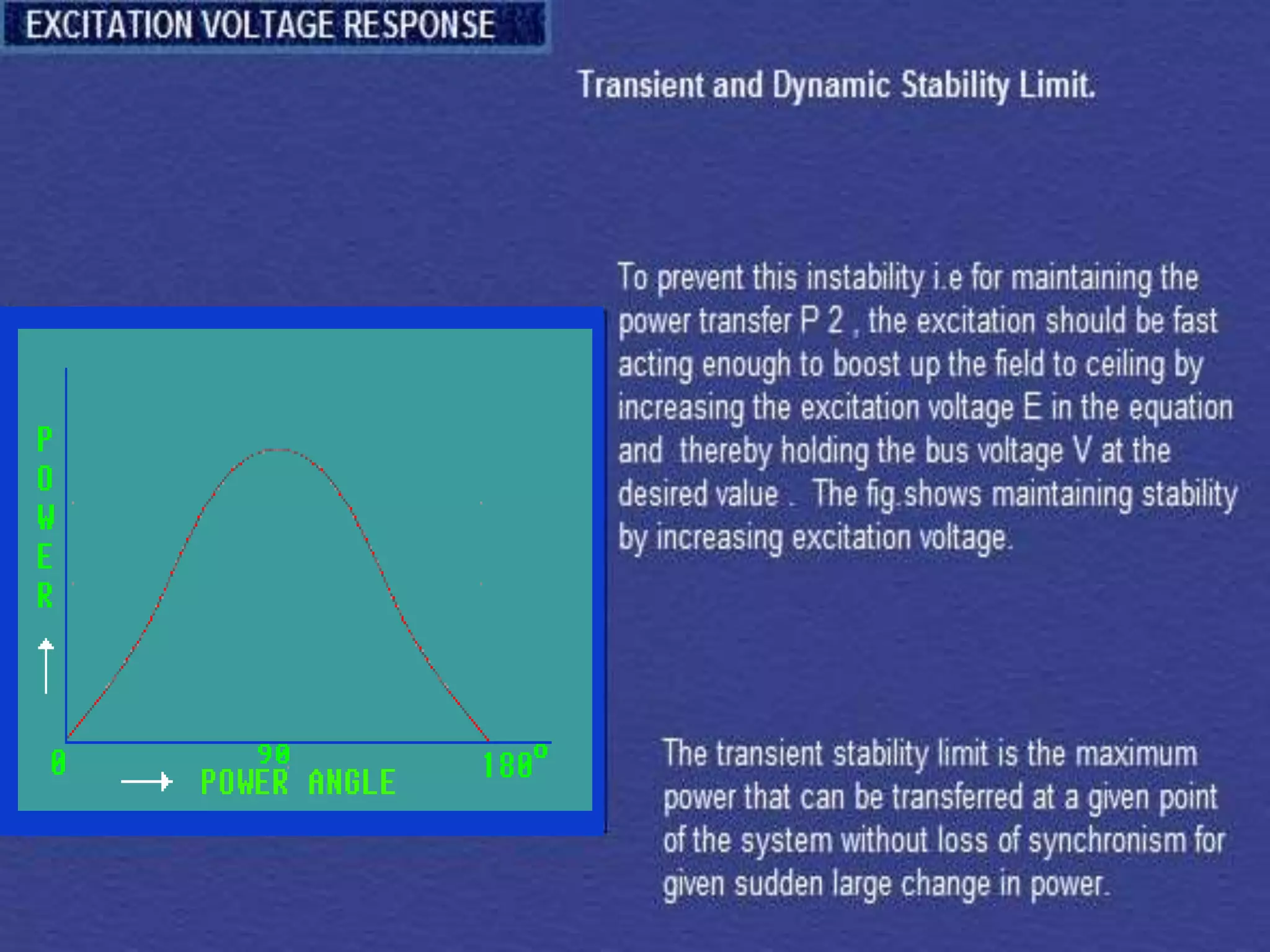
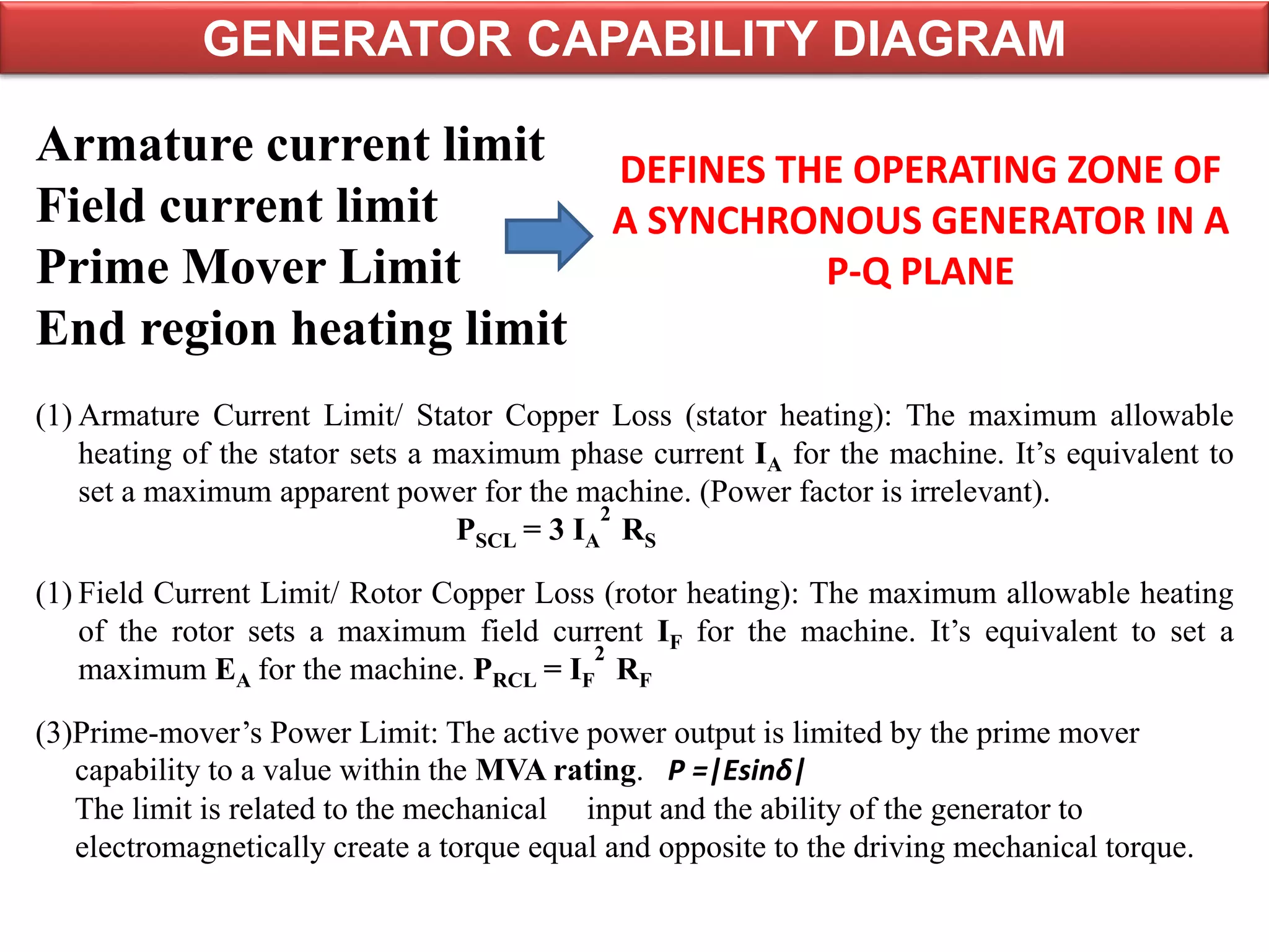
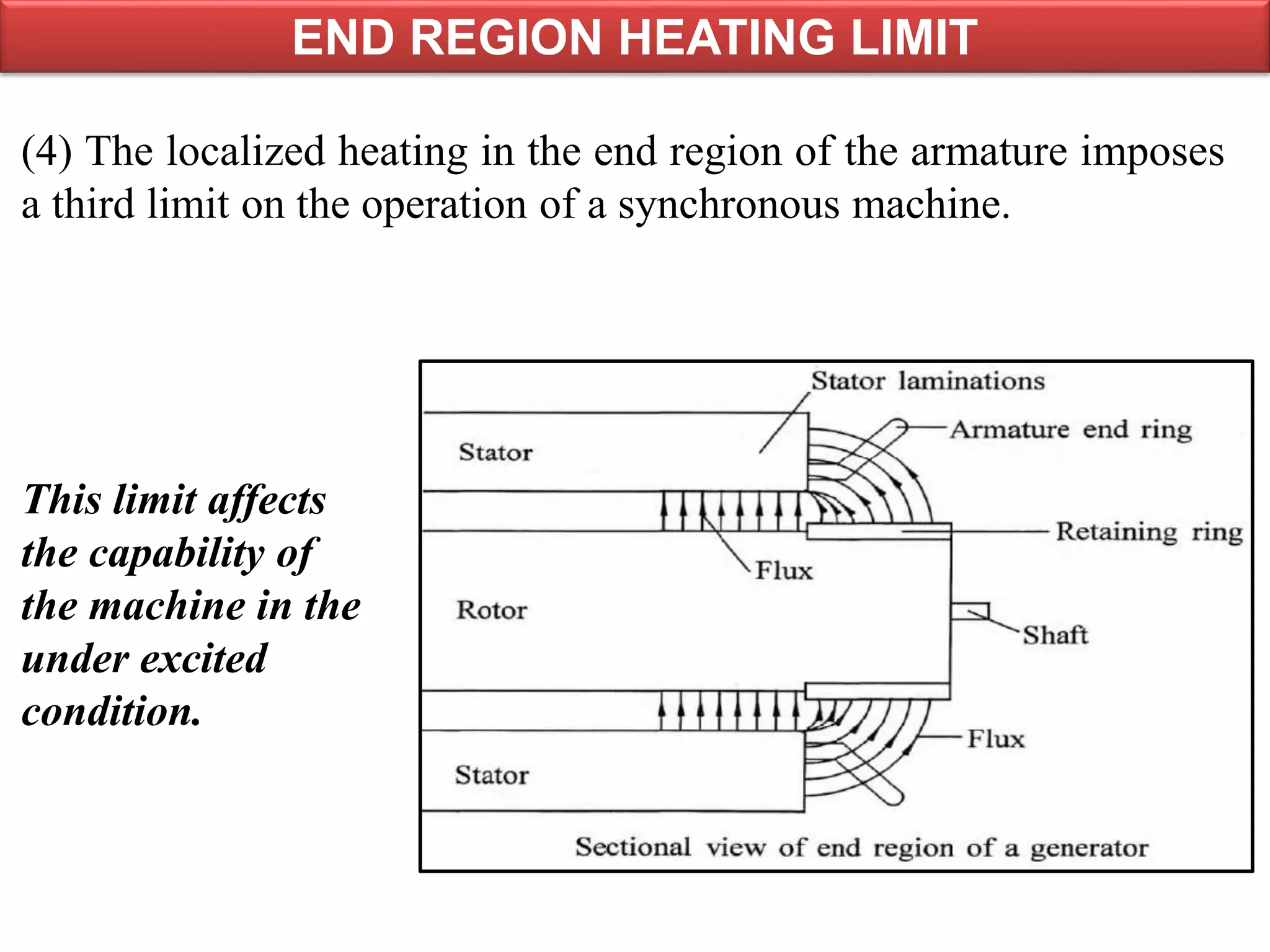
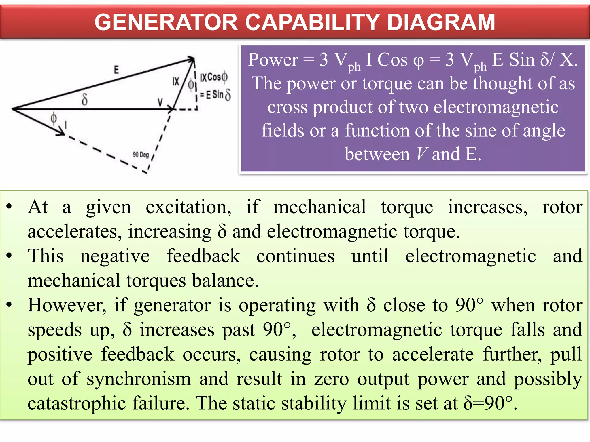
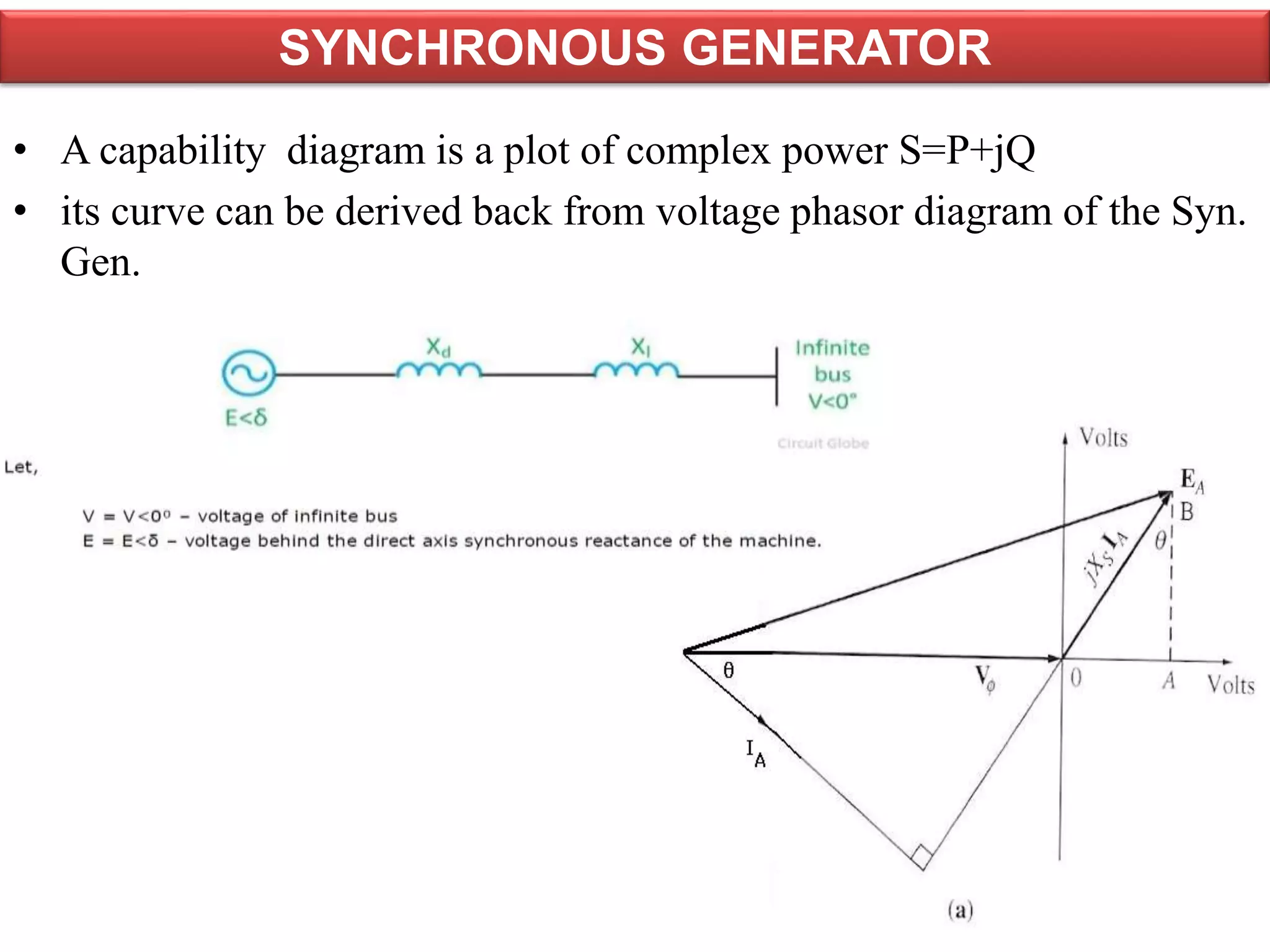
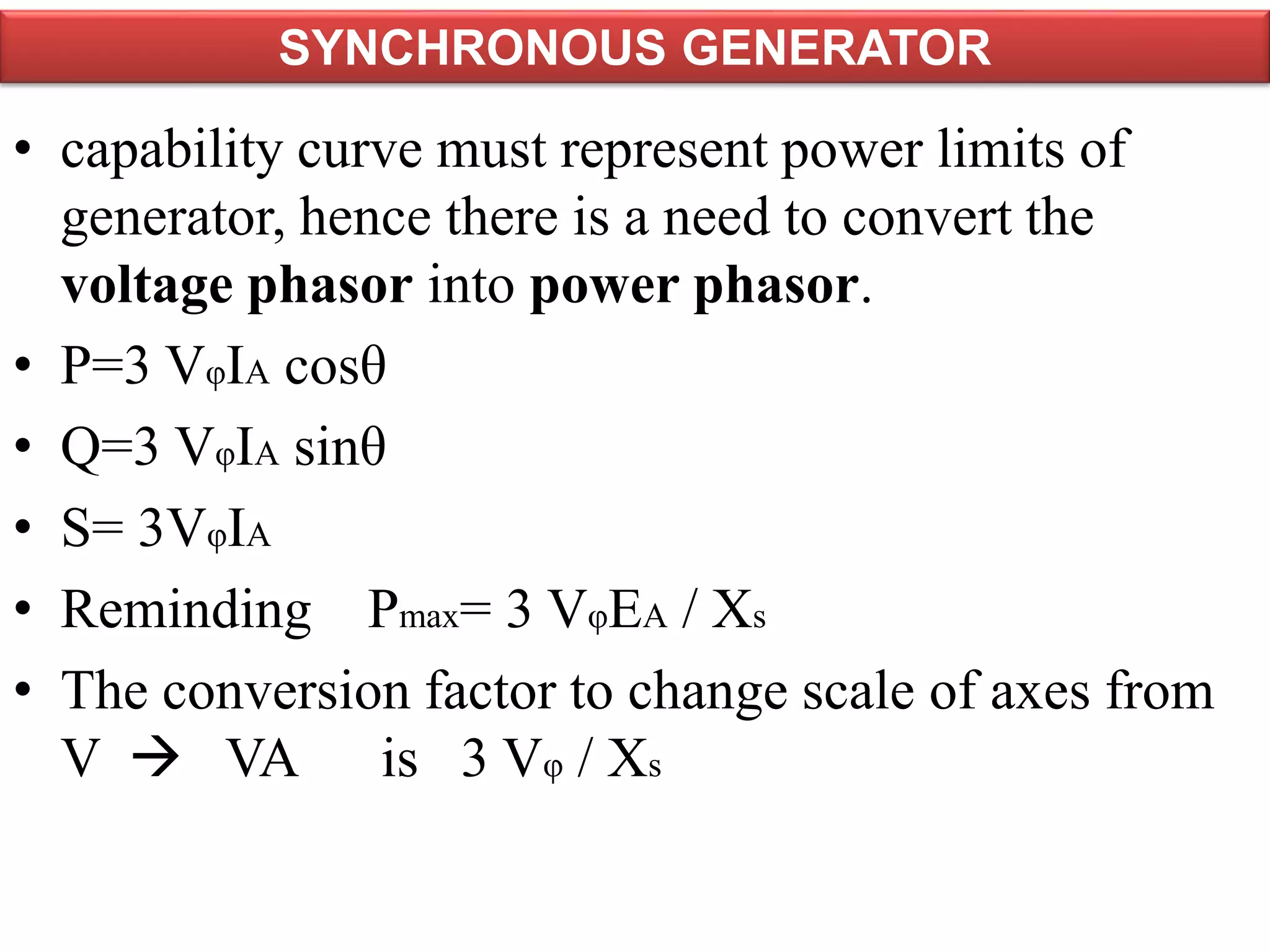
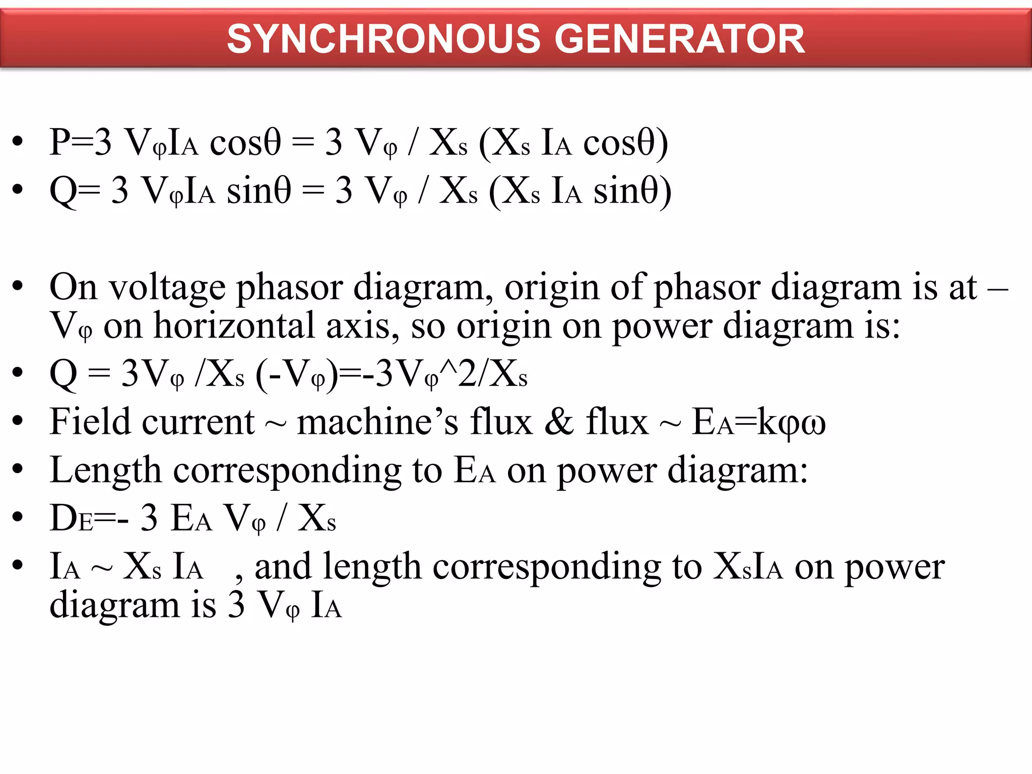
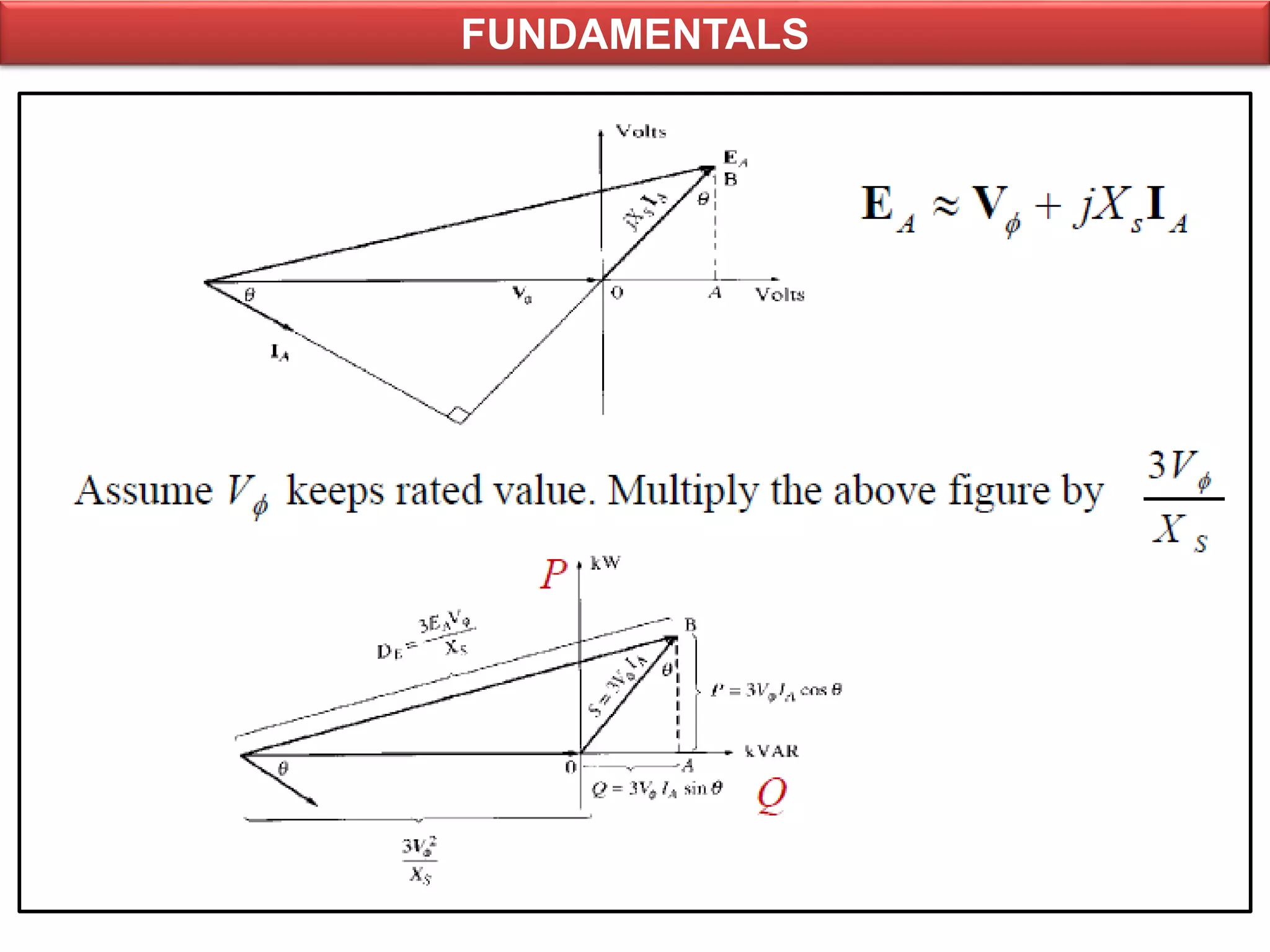
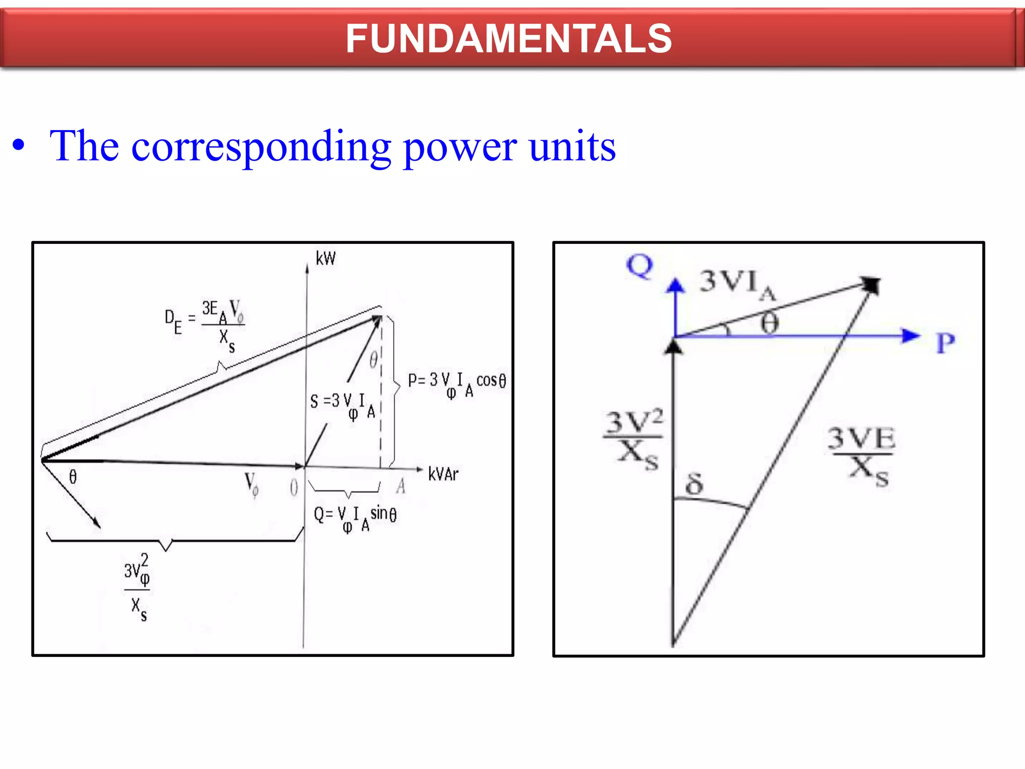
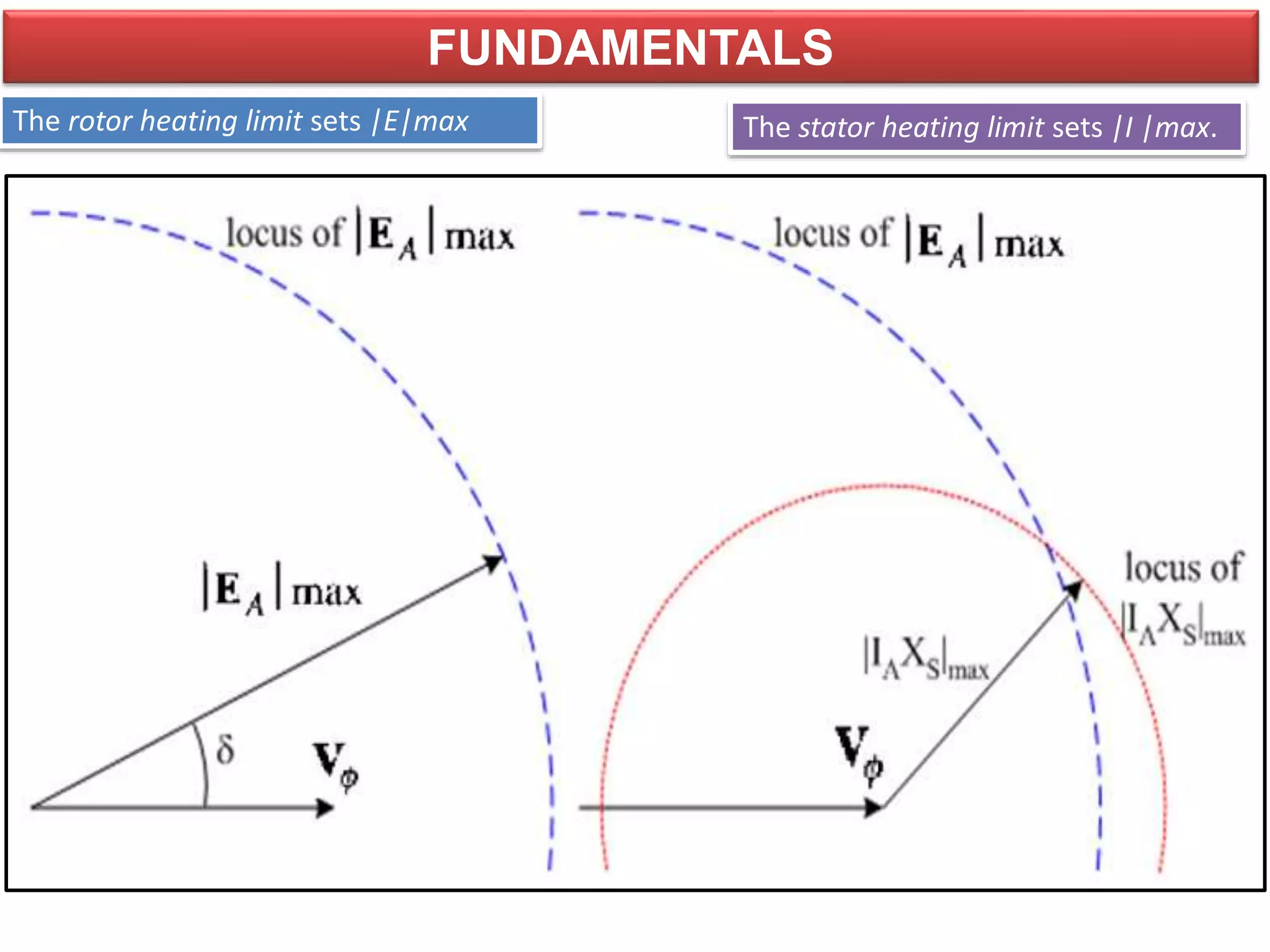
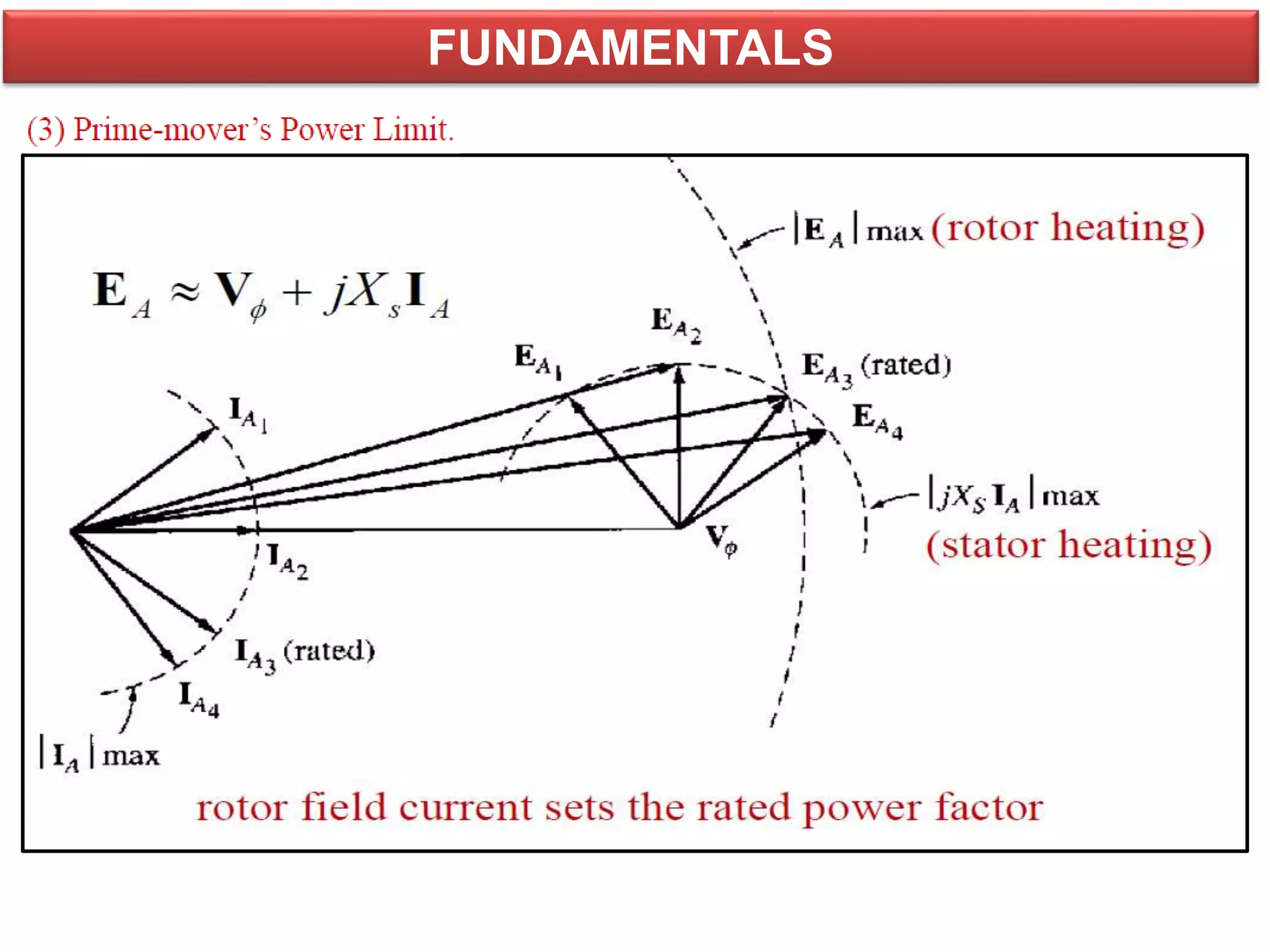

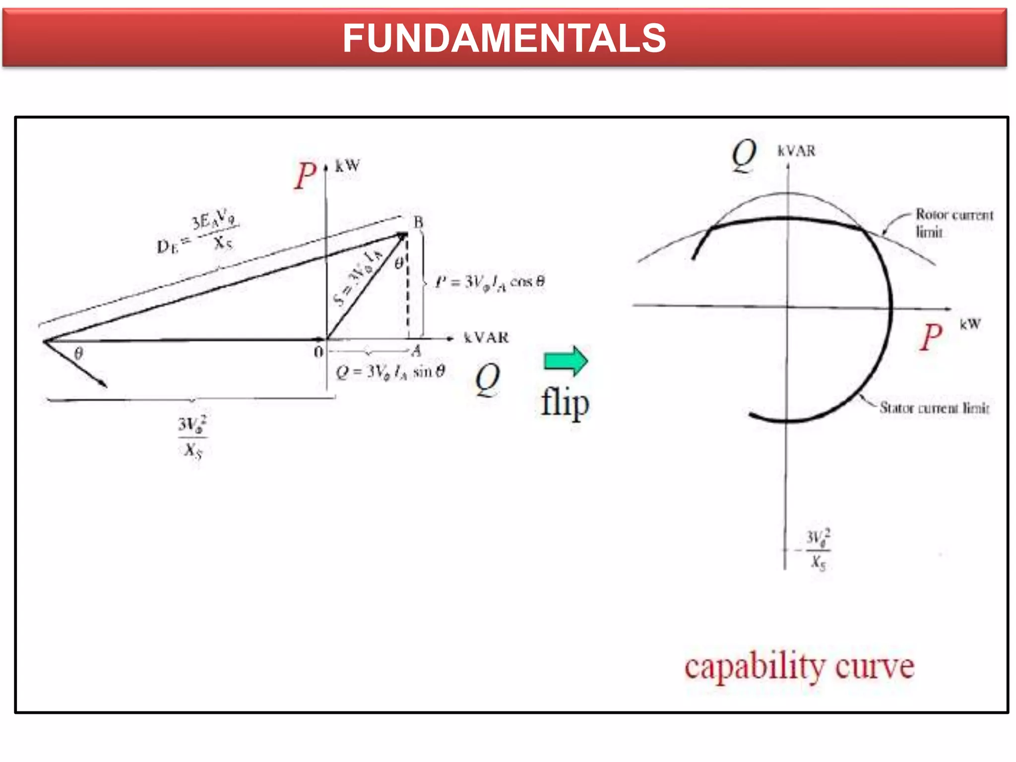
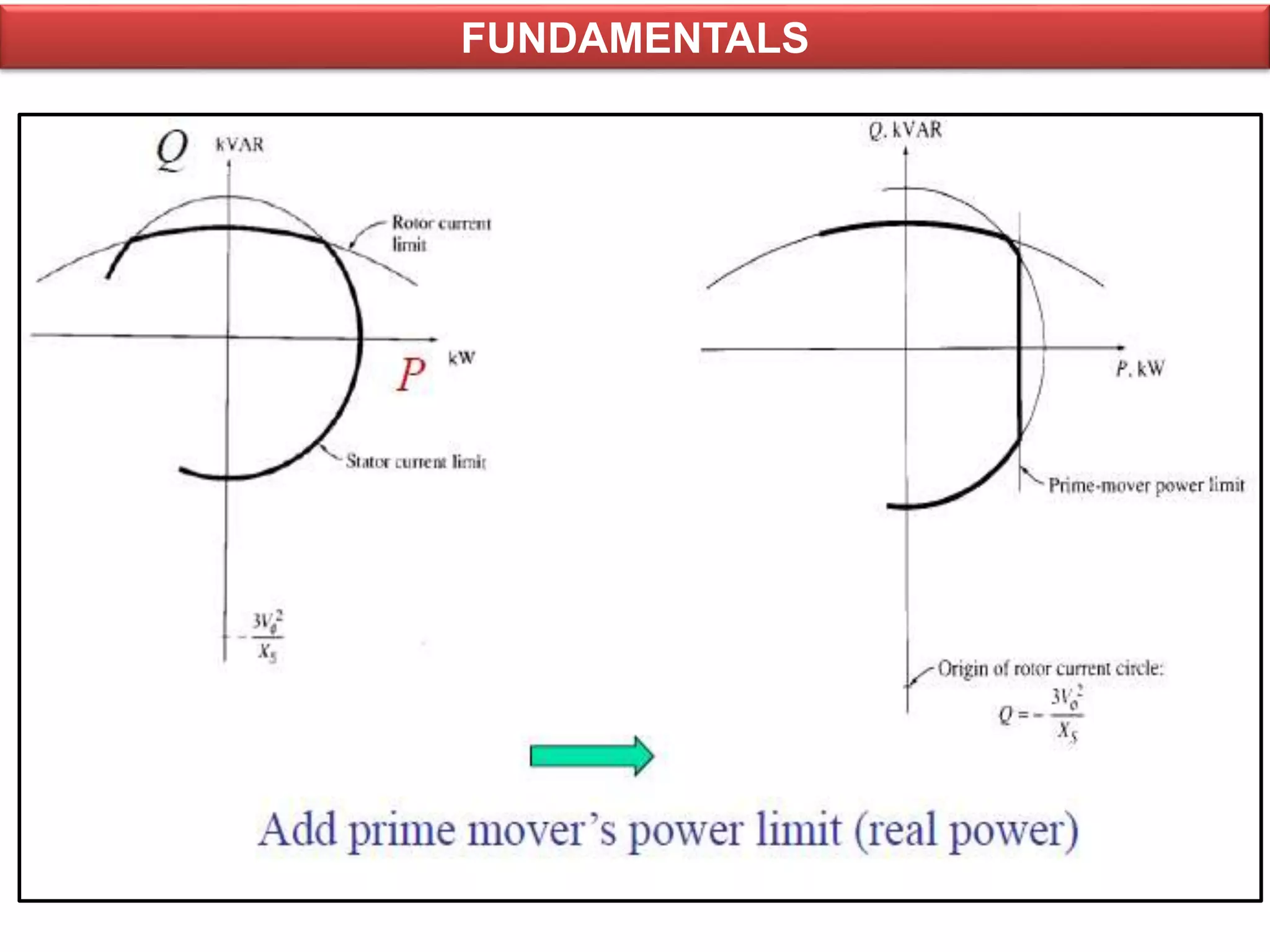
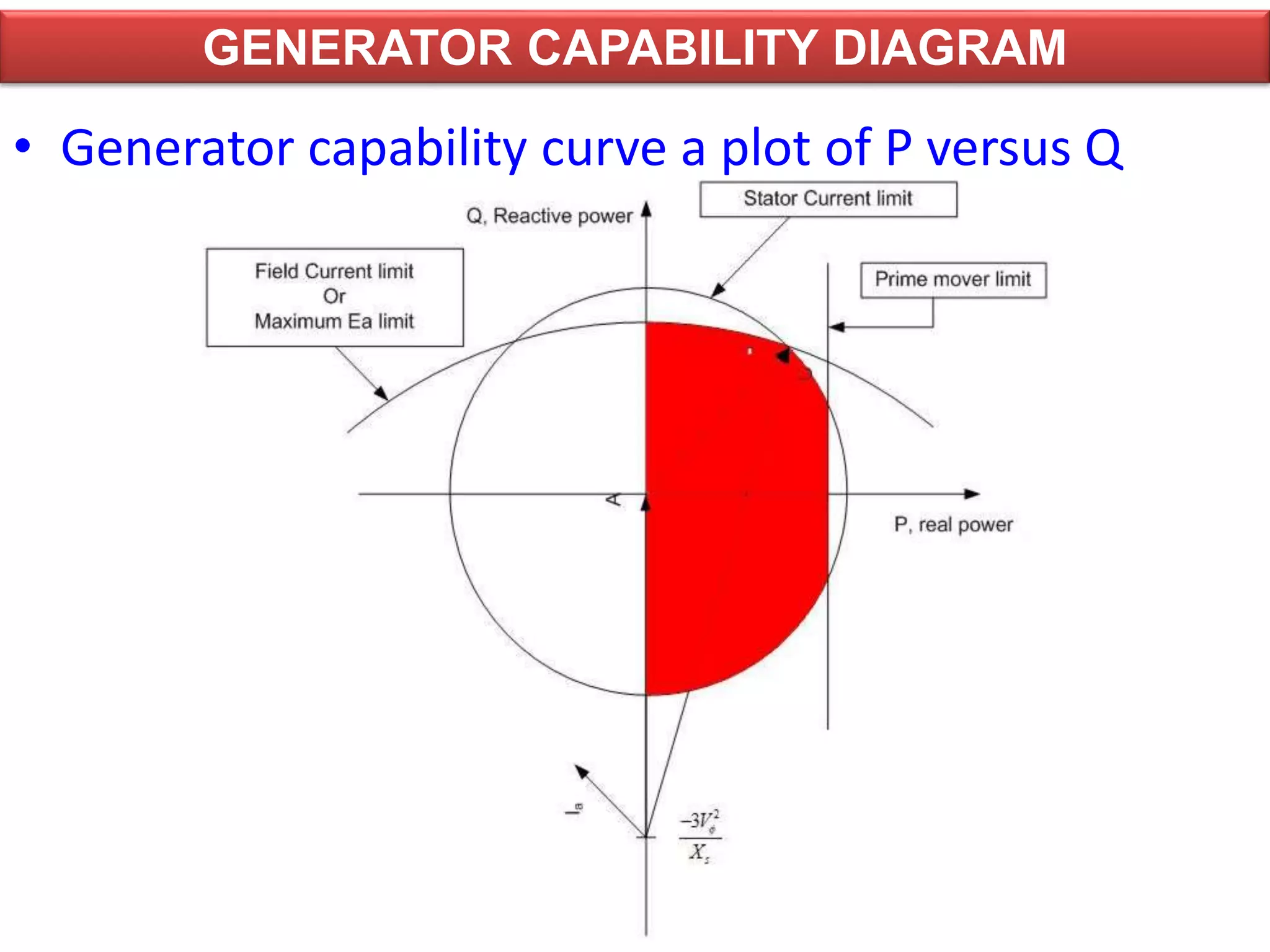
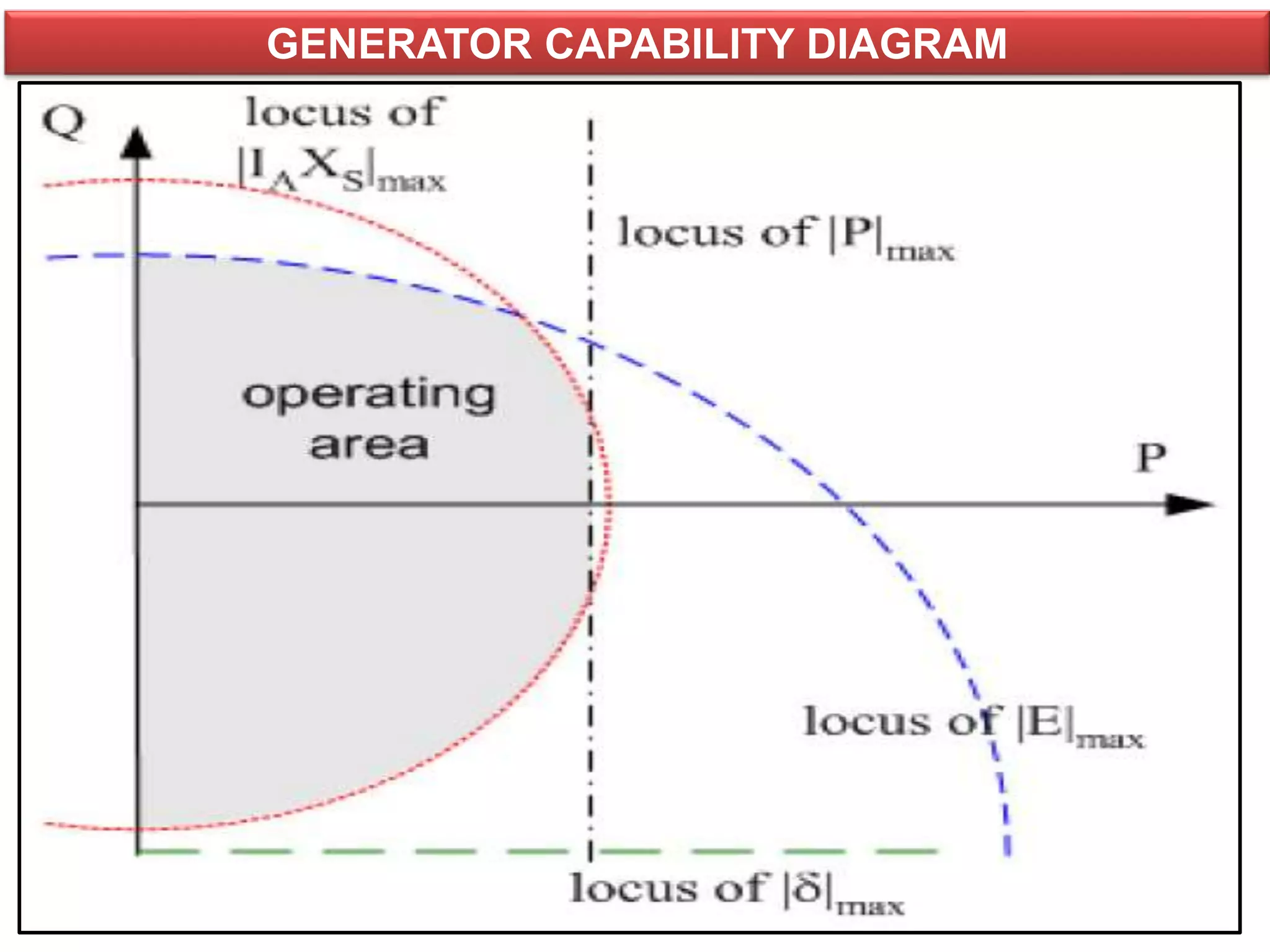
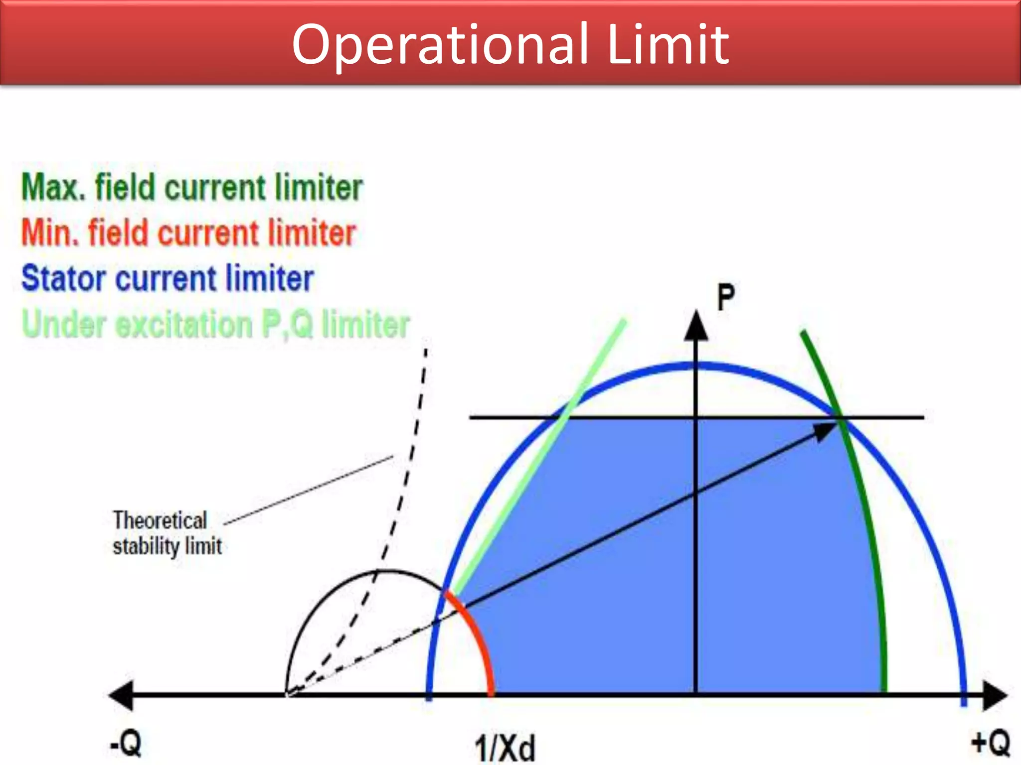
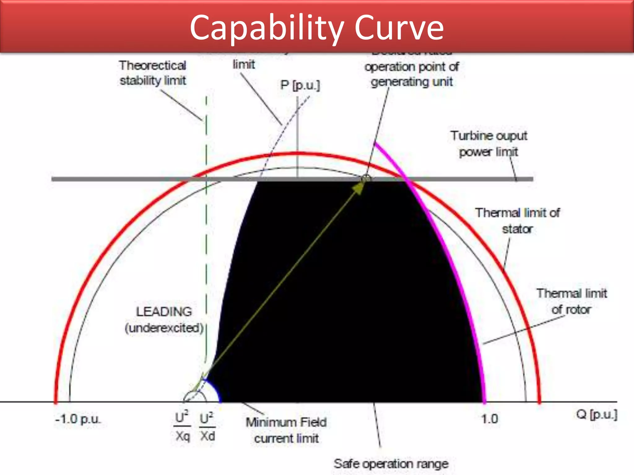
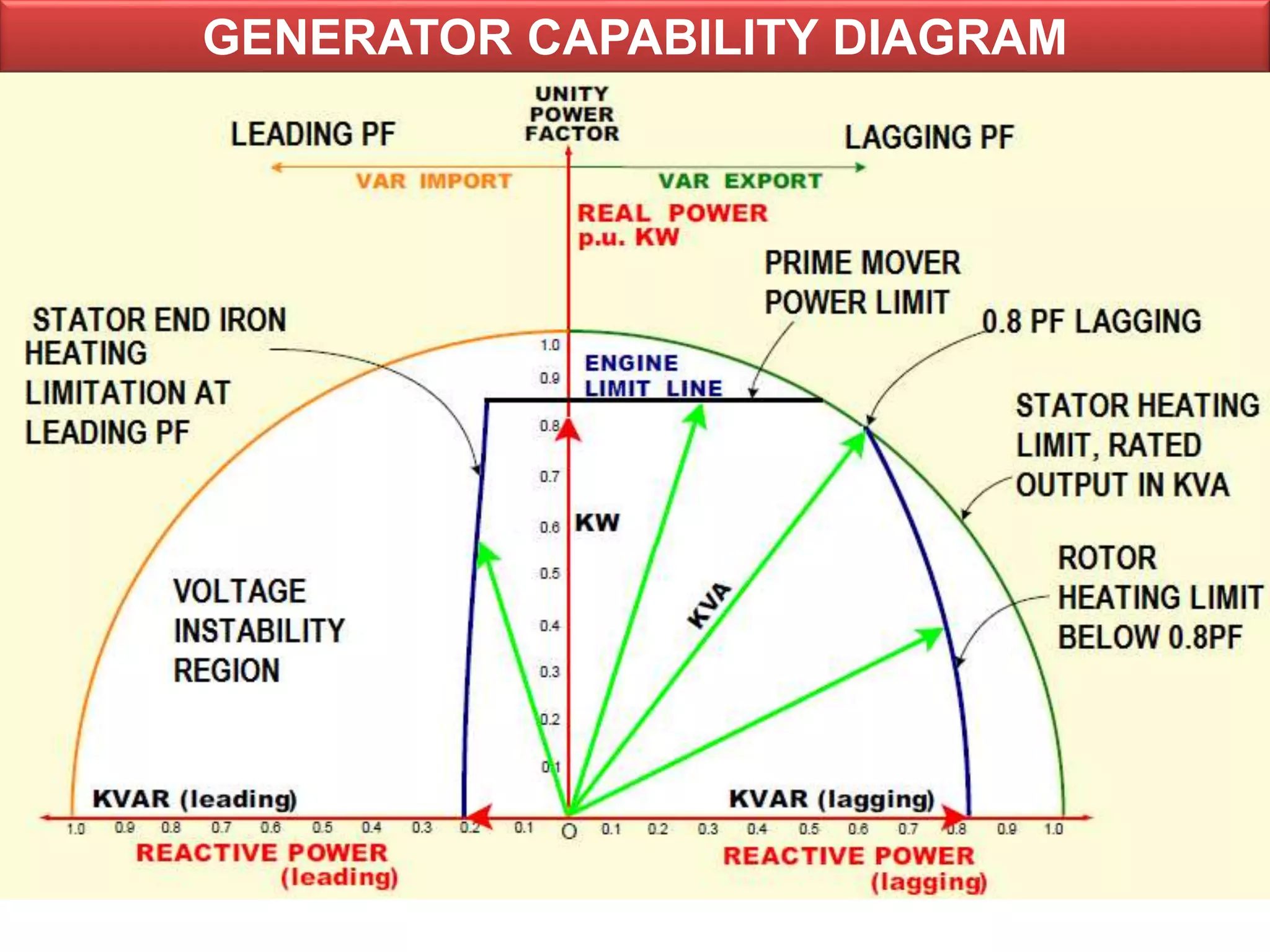


The document explains the excitation and capability curve of a synchronous generator, detailing the function of excitation systems in maintaining terminal voltage and responding to disturbances. It outlines the operational limits defined by various heating limits, which include armature current, field current, and prime mover capabilities, along with the importance of the generator capability diagram. Furthermore, it discusses the stability limits and conversion factors necessary for plotting the generator's performance in relation to power output.