

![Equation (5) can be written as:
VS = a.VL + b.I2 … (6)
where a = 1 and … (7)
nt
b = Zt … (8)
nt
Also, IS = Ym.VS + I1 … (9)
Sub (3) and (5) into (9)
IS = Ym. 1 [ VL + ZtI2 ] + nt.I2
nt
IS = Ym VL + [ YmZt + nt ] I2 … (10)
nt nt
In general form, (10) can be rewritten as
IS = c. VL + d. I2 … (11)
where c = Ym … (12)
nt
d = Y .Z + n … (13)](https://image.slidesharecdn.com/ecng3013partd-130226122618-phpapp01/75/ECNG-3013-D-5-2048.jpg)


![If the analysis is continued as before we get;
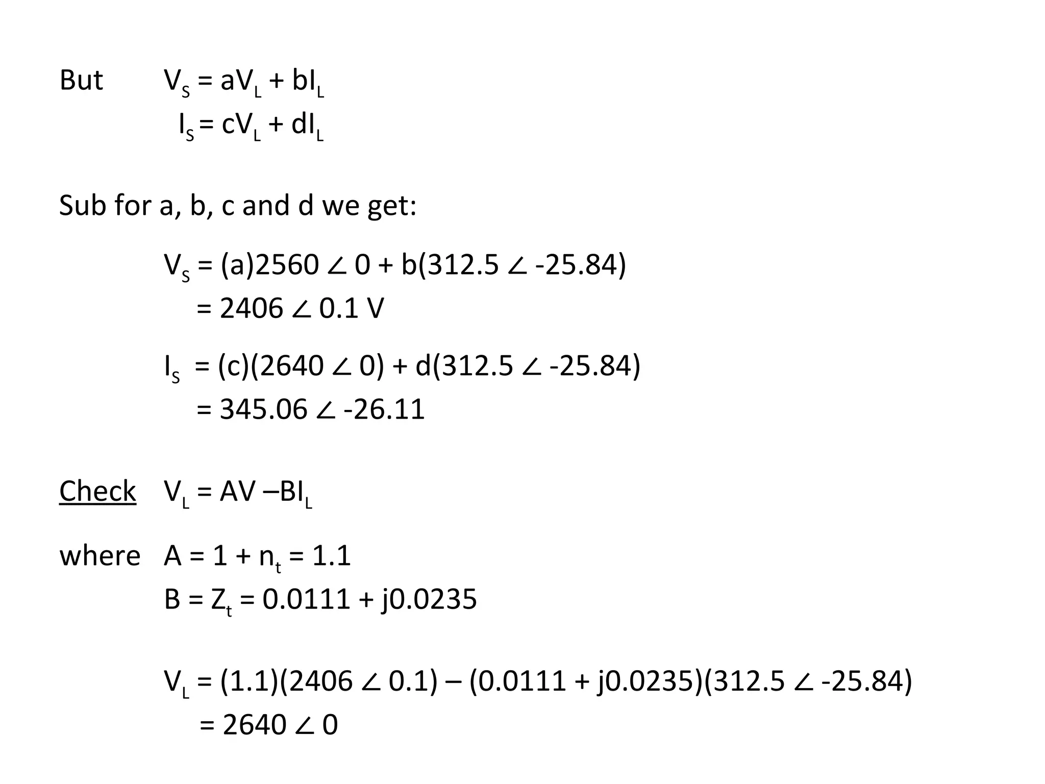
VS = aVL + bIL … (12)
IS = cVL + dIL … (13)
}
where a = 1 b = Zt
1-nt 1-nt (14)
c = Ym d = YmZt + 1 –nt
∴ 1-nt 1-nt
[ the only difference is the sign of the turns ratio.]
∴
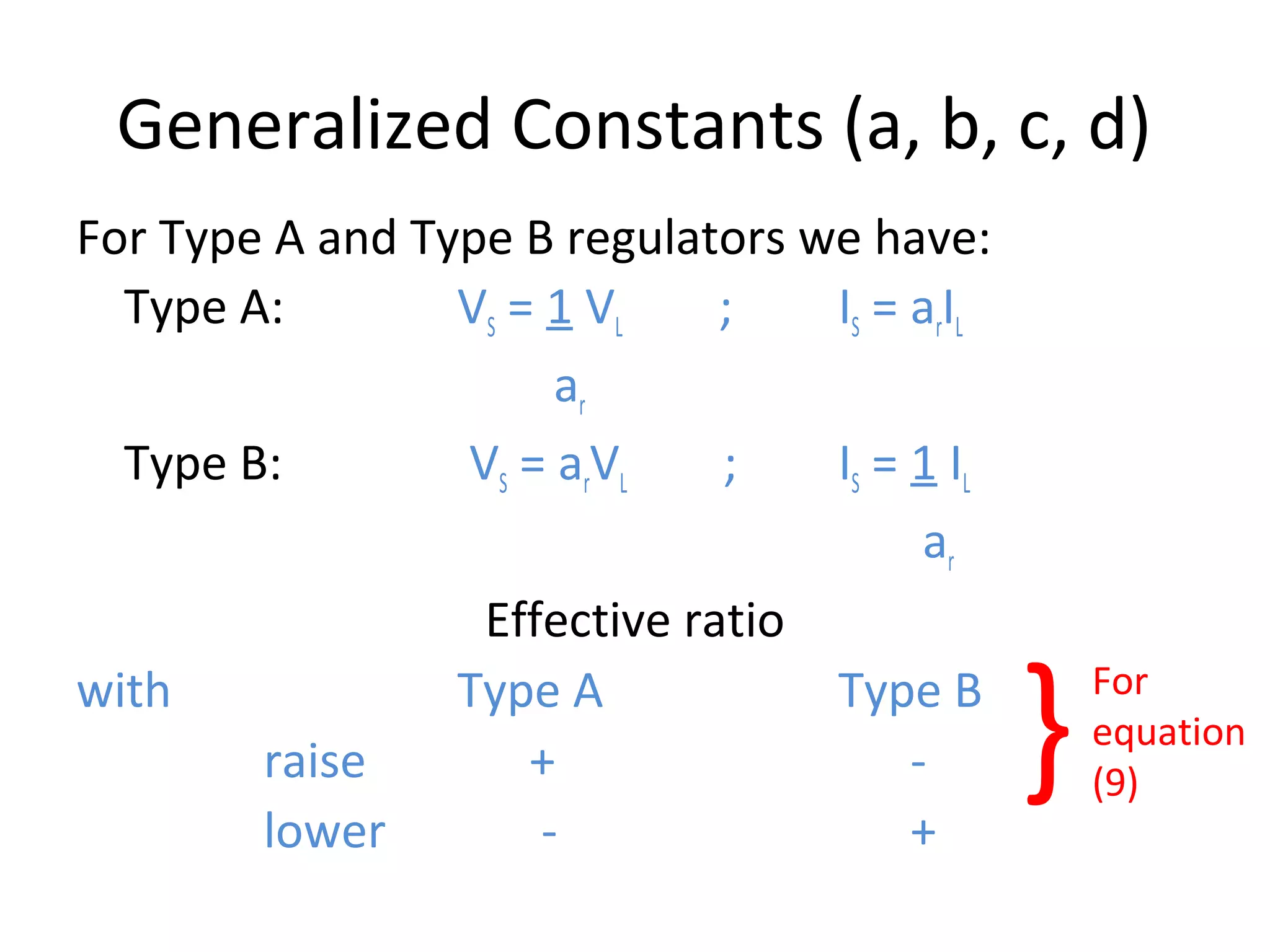
Generalized Constants for Auto-Transformer can be defined as:
a= 1
1±nt
c = Ym
1±nt
b = Zt
1±nt
d = YmZt + 1 ± nt
1±nt
} (15)
From (12) VL = 1/a.VS – b/a.IL ... (16)
Or VL = A.VS – BIL
where A = 1/a = 1±n ; B = b/a = Z … (17)](https://image.slidesharecdn.com/ecng3013partd-130226122618-phpapp01/75/ECNG-3013-D-14-2048.jpg)


![(2) VL = 2640 ∠0 V
I2 = 825 x 103 ∠ -25.84 = 312.5 ∠ -25.84 A
2640 /0
∴ a = 1/(1+0.1) = 0.9091
b = 0.0122 + j0.0235 = (0.0111 + j0.0214)
1 + 0.1
∴ c = (1.92 – j8.52) x 10-4 = (1.7364 – j7.7455) x 10-4
1 + 0.1
∴ [ ]
d = (1.92 – j8.52)(0.0122 + j0.0235) x 10-4 + 1 + 0.1
1 + 0.1
= (1.1002 – j0.000005)](https://image.slidesharecdn.com/ecng3013partd-130226122618-phpapp01/75/ECNG-3013-D-19-2048.jpg)


![Note: In type B regulator, the core excitation is constant because the
shunt winding is connected to the control circuit i.e. the
regulated line drop compensator.
Diagram gives Regulator in Raise (step up) connection (R). For Lower (L) (step
down) the switch is moved to ‘L’.
Voltage Equations Current Equations
E1 = E2 N1I1 = N2I2 … (1)
N1 N2
VS = E1 – E2 IL = IS – I1 … (2)
VL = E1 I2 = IS … (3)
E2 = N2 E1 = N2 VL I1 = N2 I2 = N2 IS … (4)
N1 N1 N1 N1
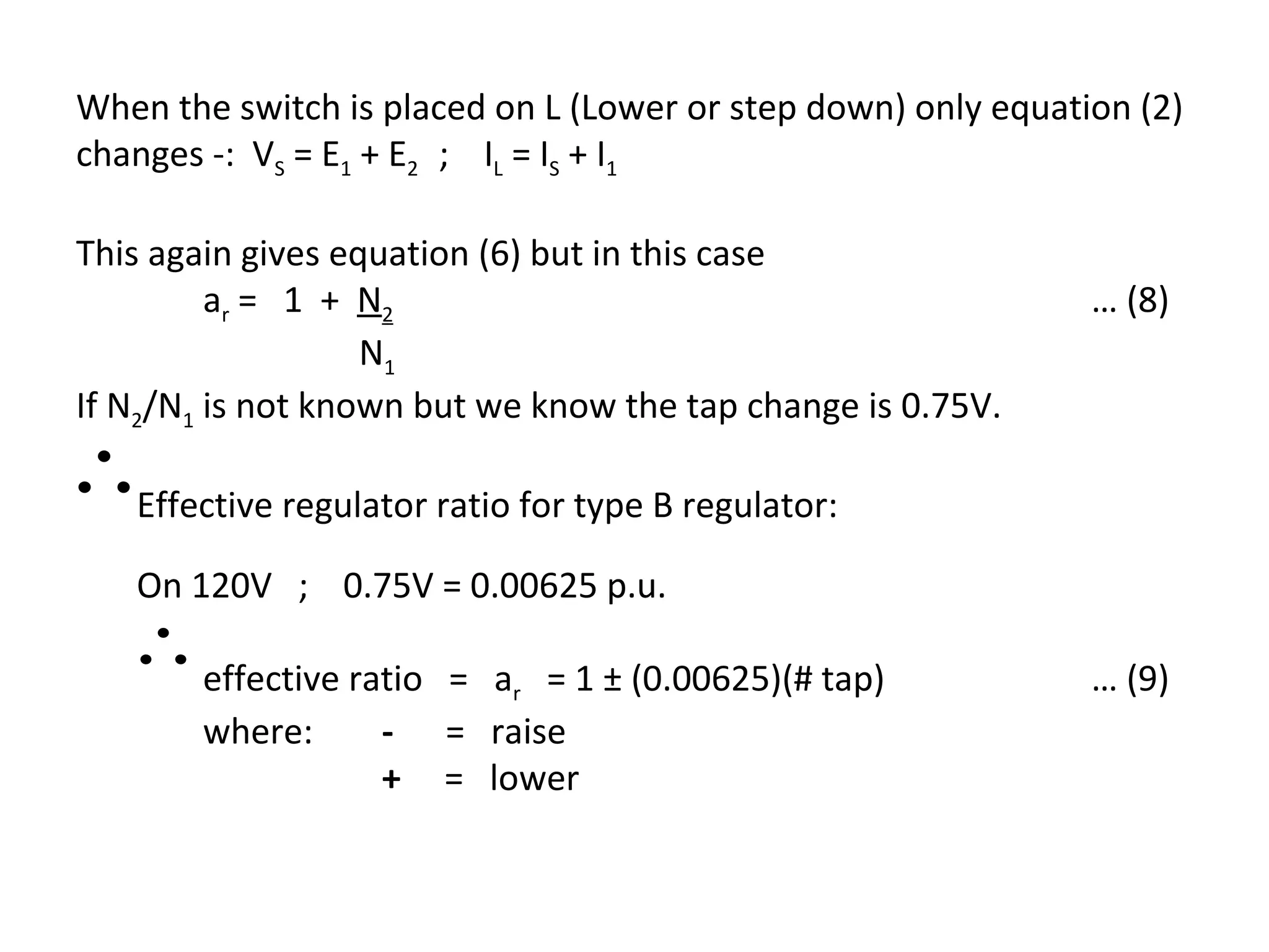
VS = [1 – N ]V
2 L [
IL = 1 – N2 ]I s … (5)
N1 N1
VS = ar . VL where ar = 1 – N2 IL = ar . IS … (6) … (7)
( N1
)](https://image.slidesharecdn.com/ecng3013partd-130226122618-phpapp01/75/ECNG-3013-D-25-2048.jpg)


![Voltage Equations
VAN aRa 0 0 Van
V = 0 … (1)
BN aRb 0 Vbn
VCN 0
0 aRc Vcn
where aRabc = effective turns ratio of the 3 single phase regulators.
Normally aRa = aRb = aRc
We can rewrite (1) in matrix format
[VLN ABC ] = [a].[V ] + [b].[ I ]
LN abc abc … (2)
Also the current equations become:
1
0 0
I a
A Ra Ia
0 1
I =
B 0 I b … (3)
a Rb
C
I
0 1 Ic
0
a Rc
OR
[ I ABC ] = [c].[VLG abc
] + [d ][ I ]
abc … (4)](https://image.slidesharecdn.com/ecng3013partd-130226122618-phpapp01/75/ECNG-3013-D-39-2048.jpg)
![Where:
aRa 0 0
[a] = 0
aRb 0
0
0 a Rc
[b] =[c ] =[0]
1
0 0
a Ra
1
[d ] = 0
0
a Rb
1
0 0
a Rc
For the typical 120 V base regulator with 0.75V / step:
0.9 ≤ aRabc ≤ 1.1 in 32 steps](https://image.slidesharecdn.com/ecng3013partd-130226122618-phpapp01/75/ECNG-3013-D-40-2048.jpg)

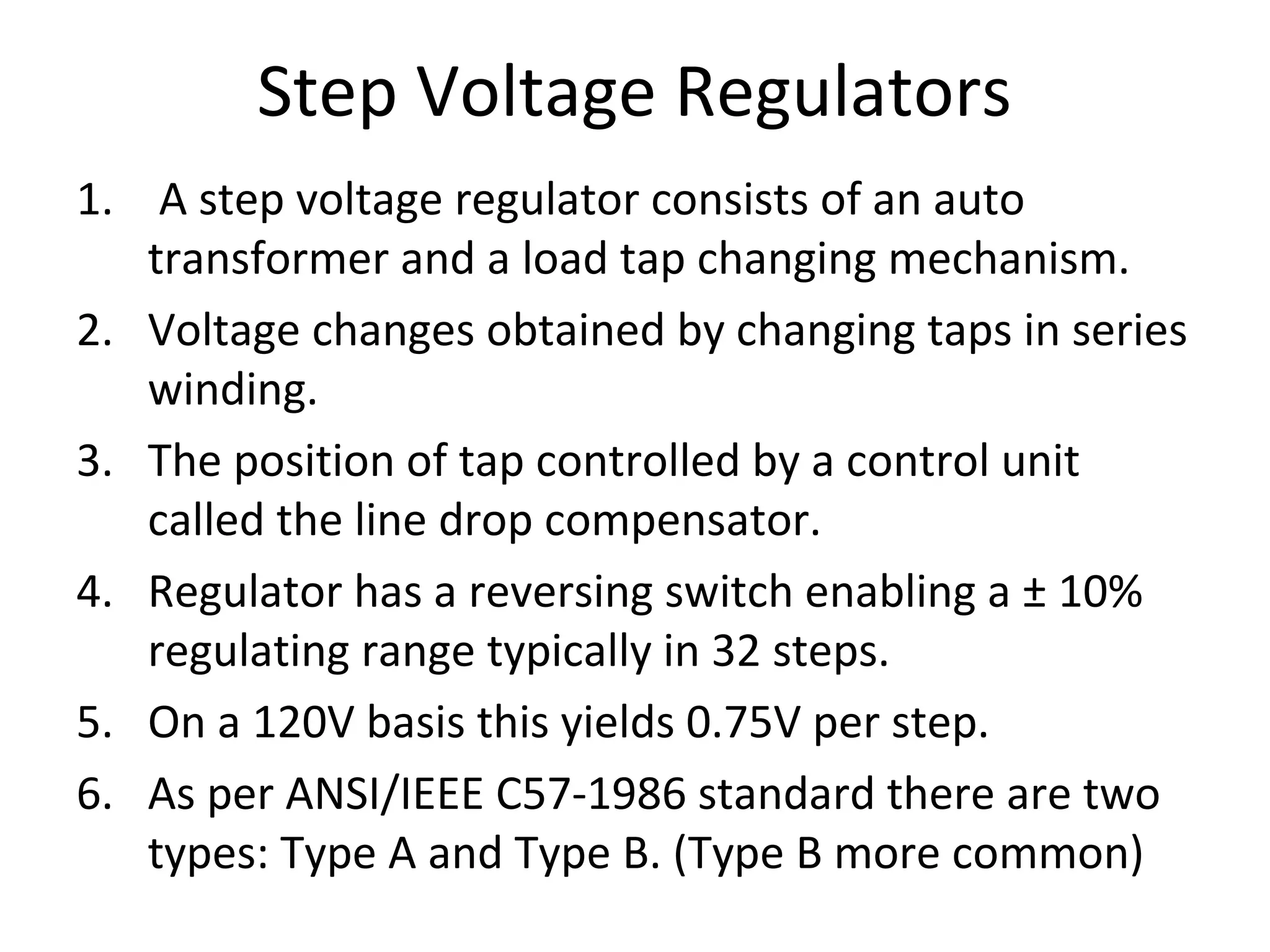
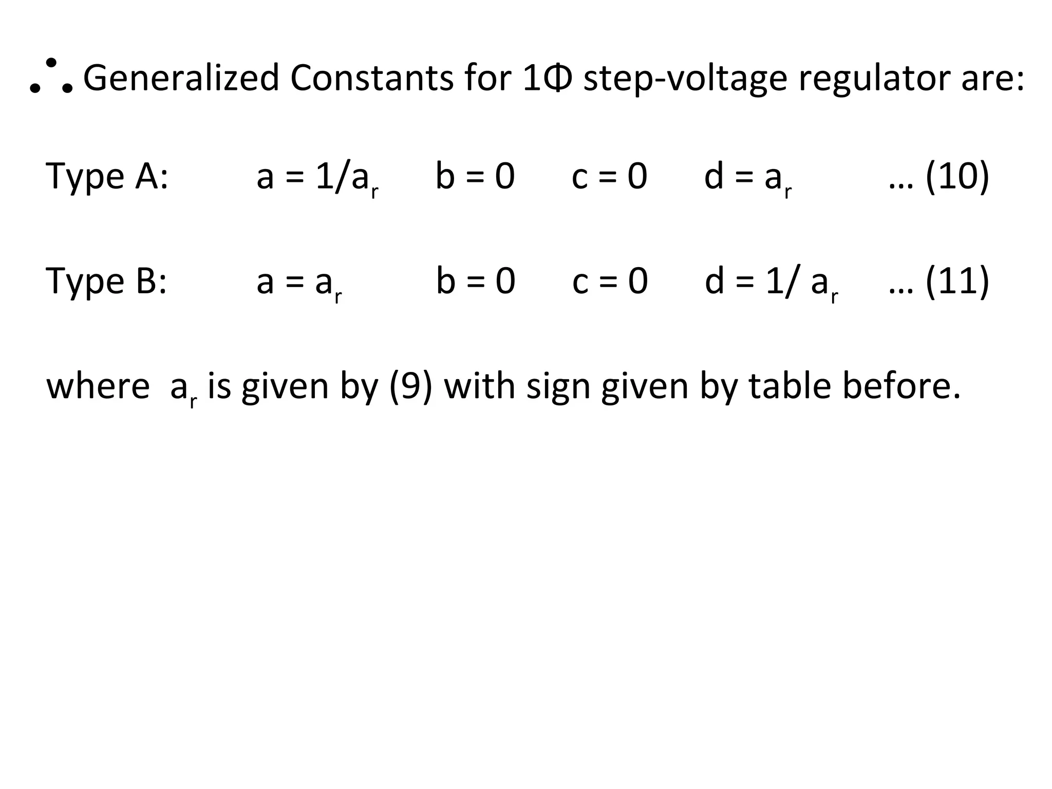
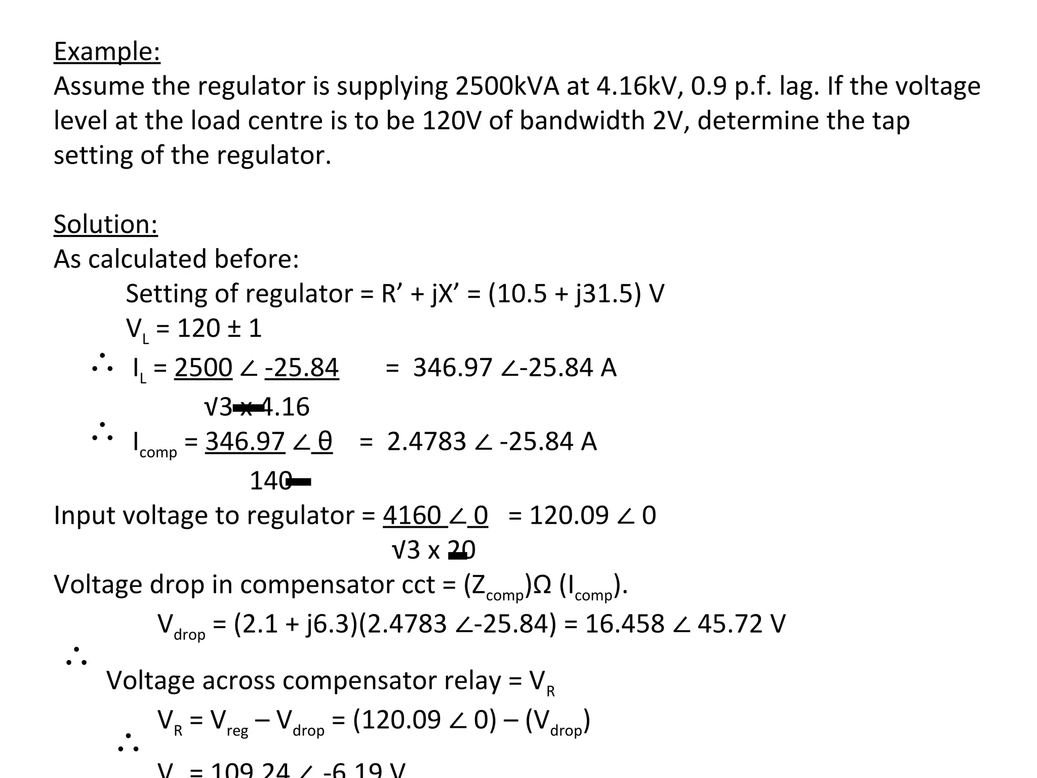
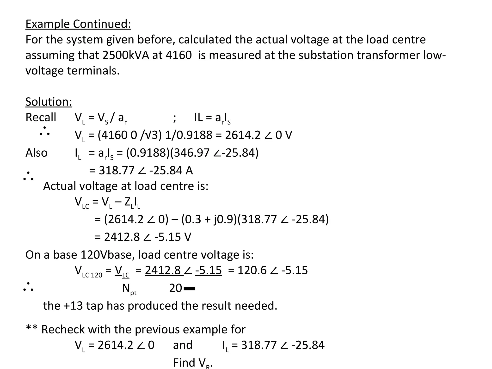
This document discusses voltage regulation and summarizes the key characteristics and equations for various voltage regulation devices: 1. Step-type voltage regulators, load tap changing transformers, and shunt capacitors are common methods for regulating voltage. 2. It provides the generalized constants (a, b, c, d) that model single-phase transformers, auto-transformers, and voltage regulators as two-port networks. These constants allow modeling the input-output voltage and current relationships. 3. It summarizes the characteristics of step voltage regulators, including the differences between Type A and Type B regulators. Type B regulators are more common and have constant core excitation since the shunt winding is connected to the control circuit. The