Load flow solution is the solution of the network under steady state conditions subjected to certain inequality constraints under which the system operates.
Generation and transmission of electric energy – voltage stress –
testing voltages-AC to DC conversion – rectifier circuits – cascaded
circuits – voltage multiplier circuits – Cockroft-Walton circuits –
voltage regulation – ripple factor – Van de-Graaff generator.
Nowadays, it is very important to maintain voltage level. Controlling of that voltage is also important. This Presentation contains methods of voltage control.
Detailed presentation created on the topic of electrical power subject on the power system analysis. Shown about Ybus details, Ybus calculations, Power flow and design, Interconnected operation of power system etc.
Symmetrical Components
Symmetrical Component Analysis
Synthesis of Unsymmetrical Phases from Their Symmetrical Components
The Symmetrical Components of Unsymmetrical Phasors
Phase Shift of Symmetrical Components in or Transformer Banks
Power in Terms of Symmetrical Components
Infinite bus bar is one which keeps constant voltage and frequency although the load varies. Thus it may behave like a voltage source with zero internal impedance and infinite rotational inertia.
This directional over current relay employs the principle of actuation of the relay....It has a metallic disc free to rotate between the poles of two...
Disadvantages of corona, radio interference, inductive interference between p...vishalgohel12195
Disadvantages of corona, radio interference, inductive interference between power and communication lines
Introduction
Disadvantages of corona.
Radio interference.
Inductive interference between power and communication lines
Generator electricals for slideshare (wecompress.com)David P
Generator or Genset electrical components
Generator electrical calculations
Generator type of loads
what is power factor & how it affects the Generator performance
Generator load calculations
Ekeeda Provides Online Video Lectures, Tutorials & Engineering Courses Available for Top-Tier Universities in India. Lectures from Highly Trained & Experienced Faculty!
Ekeeda - First Year Enginering - Basic Electrical EngineeringEkeedaPvtLtd
The First Year engineering course seems more like an extension of the subjects that students have learned in their 12th class. Subjects like Engineering Physics, Chemistry, and Mathematics, are incorporated into the curriculum. Students will learn about some of the engineering subjects in this first year, and these subjects are similar to all the branches. Everyone will learn some basics related to the other streams in their first year. Ekeeda offers Online First Year Engineering Courses for all the Subjects as per the Syllabus.
In the modern power system the reactive power compensation is one of the main issues, the transmission of active power requires a difference in angular phase between voltages at the sending and receiving points (which is feasible within wide limits), whereas the transmission of reactive power requires a difference in magnitude of these same voltages (which is feasible only within very narrow limits). The reactive power is consumed not only by most of the network elements, but also by most of the consumer loads, so it must be supplied somewhere. If we can't transmit it very easily, then it ought to be generated where it is needed." (Reference Edited by T. J. E. Miller, Forward Page ix).Thus we need to work on the efficient methods by which VAR compensation can be applied easily and we can optimize the modern power system. VAR control technique can provides appropriate placement of compensation devices by which a desirable voltage profile can be achieved and at the same time minimizing the power losses in the system. This report discusses the transmission line requirements for reactive power compensation. In this report thyristor switched capacitor is explained which is a static VAR compensator used for reactive power management in electrical systems.
Seminar Topic For Electrical and Electronics Engineering (EEE)
CFD Simulation of By-pass Flow in a HRSG module by R&R Consult.pptxR&R Consult
CFD analysis is incredibly effective at solving mysteries and improving the performance of complex systems!
Here's a great example: At a large natural gas-fired power plant, where they use waste heat to generate steam and energy, they were puzzled that their boiler wasn't producing as much steam as expected.
R&R and Tetra Engineering Group Inc. were asked to solve the issue with reduced steam production.
An inspection had shown that a significant amount of hot flue gas was bypassing the boiler tubes, where the heat was supposed to be transferred.
R&R Consult conducted a CFD analysis, which revealed that 6.3% of the flue gas was bypassing the boiler tubes without transferring heat. The analysis also showed that the flue gas was instead being directed along the sides of the boiler and between the modules that were supposed to capture the heat. This was the cause of the reduced performance.
Based on our results, Tetra Engineering installed covering plates to reduce the bypass flow. This improved the boiler's performance and increased electricity production.
It is always satisfying when we can help solve complex challenges like this. Do your systems also need a check-up or optimization? Give us a call!
Work done in cooperation with James Malloy and David Moelling from Tetra Engineering.
More examples of our work https://www.r-r-consult.dk/en/cases-en/
Cosmetic shop management system project report.pdfKamal Acharya
Buying new cosmetic products is difficult. It can even be scary for those who have sensitive skin and are prone to skin trouble. The information needed to alleviate this problem is on the back of each product, but it's thought to interpret those ingredient lists unless you have a background in chemistry.
Instead of buying and hoping for the best, we can use data science to help us predict which products may be good fits for us. It includes various function programs to do the above mentioned tasks.
Data file handling has been effectively used in the program.
The automated cosmetic shop management system should deal with the automation of general workflow and administration process of the shop. The main processes of the system focus on customer's request where the system is able to search the most appropriate products and deliver it to the customers. It should help the employees to quickly identify the list of cosmetic product that have reached the minimum quantity and also keep a track of expired date for each cosmetic product. It should help the employees to find the rack number in which the product is placed.It is also Faster and more efficient way.
Welcome to WIPAC Monthly the magazine brought to you by the LinkedIn Group Water Industry Process Automation & Control.
In this month's edition, along with this month's industry news to celebrate the 13 years since the group was created we have articles including
A case study of the used of Advanced Process Control at the Wastewater Treatment works at Lleida in Spain
A look back on an article on smart wastewater networks in order to see how the industry has measured up in the interim around the adoption of Digital Transformation in the Water Industry.
About
Indigenized remote control interface card suitable for MAFI system CCR equipment. Compatible for IDM8000 CCR. Backplane mounted serial and TCP/Ethernet communication module for CCR remote access. IDM 8000 CCR remote control on serial and TCP protocol.
• Remote control: Parallel or serial interface.
• Compatible with MAFI CCR system.
• Compatible with IDM8000 CCR.
• Compatible with Backplane mount serial communication.
• Compatible with commercial and Defence aviation CCR system.
• Remote control system for accessing CCR and allied system over serial or TCP.
• Indigenized local Support/presence in India.
• Easy in configuration using DIP switches.
Technical Specifications
Indigenized remote control interface card suitable for MAFI system CCR equipment. Compatible for IDM8000 CCR. Backplane mounted serial and TCP/Ethernet communication module for CCR remote access. IDM 8000 CCR remote control on serial and TCP protocol.
Key Features
Indigenized remote control interface card suitable for MAFI system CCR equipment. Compatible for IDM8000 CCR. Backplane mounted serial and TCP/Ethernet communication module for CCR remote access. IDM 8000 CCR remote control on serial and TCP protocol.
• Remote control: Parallel or serial interface
• Compatible with MAFI CCR system
• Copatiable with IDM8000 CCR
• Compatible with Backplane mount serial communication.
• Compatible with commercial and Defence aviation CCR system.
• Remote control system for accessing CCR and allied system over serial or TCP.
• Indigenized local Support/presence in India.
Application
• Remote control: Parallel or serial interface.
• Compatible with MAFI CCR system.
• Compatible with IDM8000 CCR.
• Compatible with Backplane mount serial communication.
• Compatible with commercial and Defence aviation CCR system.
• Remote control system for accessing CCR and allied system over serial or TCP.
• Indigenized local Support/presence in India.
• Easy in configuration using DIP switches.
Immunizing Image Classifiers Against Localized Adversary Attacksgerogepatton
This paper addresses the vulnerability of deep learning models, particularly convolutional neural networks
(CNN)s, to adversarial attacks and presents a proactive training technique designed to counter them. We
introduce a novel volumization algorithm, which transforms 2D images into 3D volumetric representations.
When combined with 3D convolution and deep curriculum learning optimization (CLO), itsignificantly improves
the immunity of models against localized universal attacks by up to 40%. We evaluate our proposed approach
using contemporary CNN architectures and the modified Canadian Institute for Advanced Research (CIFAR-10
and CIFAR-100) and ImageNet Large Scale Visual Recognition Challenge (ILSVRC12) datasets, showcasing
accuracy improvements over previous techniques. The results indicate that the combination of the volumetric
input and curriculum learning holds significant promise for mitigating adversarial attacks without necessitating
adversary training.
Hybrid optimization of pumped hydro system and solar- Engr. Abdul-Azeez.pdffxintegritypublishin
Advancements in technology unveil a myriad of electrical and electronic breakthroughs geared towards efficiently harnessing limited resources to meet human energy demands. The optimization of hybrid solar PV panels and pumped hydro energy supply systems plays a pivotal role in utilizing natural resources effectively. This initiative not only benefits humanity but also fosters environmental sustainability. The study investigated the design optimization of these hybrid systems, focusing on understanding solar radiation patterns, identifying geographical influences on solar radiation, formulating a mathematical model for system optimization, and determining the optimal configuration of PV panels and pumped hydro storage. Through a comparative analysis approach and eight weeks of data collection, the study addressed key research questions related to solar radiation patterns and optimal system design. The findings highlighted regions with heightened solar radiation levels, showcasing substantial potential for power generation and emphasizing the system's efficiency. Optimizing system design significantly boosted power generation, promoted renewable energy utilization, and enhanced energy storage capacity. The study underscored the benefits of optimizing hybrid solar PV panels and pumped hydro energy supply systems for sustainable energy usage. Optimizing the design of solar PV panels and pumped hydro energy supply systems as examined across diverse climatic conditions in a developing country, not only enhances power generation but also improves the integration of renewable energy sources and boosts energy storage capacities, particularly beneficial for less economically prosperous regions. Additionally, the study provides valuable insights for advancing energy research in economically viable areas. Recommendations included conducting site-specific assessments, utilizing advanced modeling tools, implementing regular maintenance protocols, and enhancing communication among system components.
Hierarchical Digital Twin of a Naval Power SystemKerry Sado
A hierarchical digital twin of a Naval DC power system has been developed and experimentally verified. Similar to other state-of-the-art digital twins, this technology creates a digital replica of the physical system executed in real-time or faster, which can modify hardware controls. However, its advantage stems from distributing computational efforts by utilizing a hierarchical structure composed of lower-level digital twin blocks and a higher-level system digital twin. Each digital twin block is associated with a physical subsystem of the hardware and communicates with a singular system digital twin, which creates a system-level response. By extracting information from each level of the hierarchy, power system controls of the hardware were reconfigured autonomously. This hierarchical digital twin development offers several advantages over other digital twins, particularly in the field of naval power systems. The hierarchical structure allows for greater computational efficiency and scalability while the ability to autonomously reconfigure hardware controls offers increased flexibility and responsiveness. The hierarchical decomposition and models utilized were well aligned with the physical twin, as indicated by the maximum deviations between the developed digital twin hierarchy and the hardware.
Planning Of Procurement o different goods and services
Fundamentals of power system
1. Power System Operation & Control, 6th Semester
Prepared by Balaram Das, EE Department, GIET, Gunupur
Chapter-1
Fundamentals of Power System
Introduction:
The waveform of voltage at the buses of a power system can be assumed to be
purely sinusoidal and of constant frequency. In developing most of the theory in this
subject we will concerned with the phasor representations of sinusoidal voltages and
currents and use the capital letters V and I to indicate these phasor (with appropriate
subscripts where required). Vertical bars enclosing V & I designated the magnitudes of
the phasor. Lowercase letters are usually indicates instantaneous values.
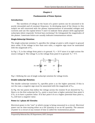
Single-Subscript Notation:
The single-subscript notation Va specifies the voltage at point a with respect to ground
(zero volts). If the voltage is less than zero volts, a negative sign must be associated
with the magnitude of Va.
In Fig.1, Va is the voltage from point a to ground. Va = 10 V since it is right across the
source voltage E. The voltage Vb is the voltage from point b to ground. Vb = 4 V.
Fig.1: Defining the use of single subscript notation for voltage levels.
Double subscript Notation:
The double subscript notation Vab specifies point a as the higher potential. If this is
not the case, a negative sign must be associated with the magnitude of Vab.
In Fig. the two points that define the voltage across the resistor R are denoted by Vab.
Since a is the first subscript for Vab, point a must have a higher potential than point b
if Vab is to have a positive value. If in fact point b Is at a higher potential than point a,
Vab will have a negative value.
Power in 1-phase AC Circuits:
Electrical power is the “rate” at which energy is being consumed in a circuit. Electrical
power can be time-varying either as a DC quantity or as an AC quantity. The amount
of power in a circuit at any instant of time is called the instantaneous power.
2. Power System Operation & Control, 6th Semester
Prepared by Balaram Das, EE Department, GIET, Gunupur
For DC circuit,
Where: V is the dc voltage, I is the dc current and R is the value of the resistance.
For AC circuit,
Complex Power:
Complex power is “the complex sum of real and reactive powers”. It is also termed as
apparent power, measured in terms of Volt Amps (or) in Kilo Volt Amps (kVA). The
rectangular power of complex power is given below:
Where, S is complex or apparent power, P is real power measured in terms of Watts
and Q is reactive power measured in terms of Volt Amps Reactive (generally in kVAR).
The polar form of complex power is given below:
In addition, the complex power for transformer can be written as, S=VI. The complex
power for transmission lines is, S=VI*, where I* is complex conjugate of current. The
magnitude of the complex power is the apparent power.
The Power Triangle:
Power Triangle is the representation of a right angle triangle showing the relation
between active power, reactive power and apparent power.
3. Power System Operation & Control, 6th Semester
Prepared by Balaram Das, EE Department, GIET, Gunupur
The power which is actually consumed or utilized in an AC Circuit is called True
power or Active Power or real power. It is measured in kilowatt (kW) or MW. The
power which flows back and forth that means it moves in both the direction in the
circuit or reacts upon it, is called Reactive Power. The reactive power is measured in
kVAR or MVAR. The product of RMS value of voltage and current is known as
Apparent Power. This power is measured in KVA or MVA.
Direction of Power Flow:
Example 1.1. Two ideal voltage sources designated as machines 1 and 2 are
connected, as shown in Fig. If E1 = 100 V, E2 = 100∟30° V, and Z = 0 + j5 Ω,
determine (a) whether each machine is generating or consuming real power and
the amount, (b) whether each machine is receiving or supplying reactive power
and the amount, and (c) the P and Q absorbed by the impedance.
4. Power System Operation & Control, 6th Semester
Prepared by Balaram Das, EE Department, GIET, Gunupur
Solution:
Current entering box-1 = -I
Current entering box-2 = I
Reactive power absorbed in the series impedance is
NOTE: Machine-1 may be expected to be a generator because of the current direction
and polarity markings. However, since P1 is positive and Q1 is negative, the machine
consumes energy at the rate of 1000W and supplies reactive power of 268 VAR. The
machine is actually a motor.
Machine-2, expected to be a motor, has negative P2 and negative Q2. Therefore, this
machine generates energy at the rate of 1000W and supplies reactive power of 268
VAR. The machine is actually a generator.
Note that the supplied reactive power of 268 + 268 =536 VAR, which is required by the
inductive reactance of j5Ω. Since the impedance is purely reactive, no P is consumed
by the impedance, and all the watts generated by machine 2 are transferred to
machine 1.
Voltage and Current in Balanced Three Phase Circuits
Star Connection (Y)
5. Power System Operation & Control, 6th Semester
Prepared by Balaram Das, EE Department, GIET, Gunupur
Star Connection is obtained by connecting together similar ends of the three coils. The
other ends are joined to the line wires. The common point is called the neutral. Star
Connection, is also called Three Phase 4 wires system. The Voltage between Line and
Neutral is called Phase voltage and the voltage between two Lines is called Line
Voltage.
Star Connection Delta Connection
It is seen from the fig 2 that;
Line voltages are 120° apart from each other
6. Power System Operation & Control, 6th Semester
Prepared by Balaram Das, EE Department, GIET, Gunupur
Line voltages are 30° leading from the corresponding phase voltages
The angle Ф between line currents and respective line voltages are (30°+Ф), i.e.
each line current is lagging (30°+Ф) from the corresponding line voltage.
Example 1.2:
A balanced Y-connected load of 8+j6 Ω per phase connected to a balanced 3-
phase 400V supply. Find the line current, power factor, power and total volt
amp.
Solution:
Example 1.3
A balanced three-phase load connected in star consists of (6+8) Ω impedance
in each phase. It is connected to a three phase supply of 400 V, 50 Hz. Find
(i) Phase current (ii) Line current (iii) Per phase power and (iv) Total power.
7. Power System Operation & Control, 6th Semester
Prepared by Balaram Das, EE Department, GIET, Gunupur
Per-unit quantities:
The per unit value of any quantity is defined as the ratio of actual value in any unit
and the base or reference value in the same unit.
The per unit value are dimensionless.
Actual Quantity Base Quantity
Voltage, V1
Current, I1
Base Voltage, VB
Base Current, IB
8. Power System Operation & Control, 6th Semester
Prepared by Balaram Das, EE Department, GIET, Gunupur
Resistance, R1
Reactance, X1
Active power, P1
Reactive power, Q1
Impedance, Z1
Base Power, SB
Base Impedance, ZB
Out of four base quantity,
SB and VB …….selected base quantity
ZB and IB ………derived base quantity from selected base
For a single-phase system, the following formulas relate the various quantities.
Per unit values
Voltage in pu
Current in pu
Resistance in pu
Reactance in pu
Active power in pu
Reactive power in pu
Impedance in pu
Advantages of per-unit calculation
1. Manufacturers usually specify the impedance of a piece of apparatus in
percent or per-unit on the base of the name plate rating.
2. The per-unit impedances of machines of same type and widely different
rating usually lie within narrow range.
3. For a transformer, when impedance in ohm is specified, it must be clearly
mentioned whether it is with respect to primary or secondary. The per-unit
9. Power System Operation & Control, 6th Semester
Prepared by Balaram Das, EE Department, GIET, Gunupur
impedance of the transformer, once expressed on proper base, is the same
referred to either side.
4. The way in which the three-phase transformers are connected does not
affect the per-unit impedances although the transformer connection does
determine the relation between the voltage bases on the two sides of the
transformer.
5. Calculation using pu system is easier.
Changing the Base in Per- Unit Quantities: (or, Per-unit quantities on a different
base:
From eq.() It is to be noted that the per-unit impedance is directly proportional to base
MVA and inversely proportional to (base kV)2. Therefore, to change from per-unit
impedance on a given base to per-unit impedance on a new base, the following
equation applies:
System-01 System-02
From equation(21) and (22)
Example: 1.4
A three phase 500 MVA, 22 kV generator has winding reactance of 1.065 Ω. Find
its per unit reactance.
Solution:
10. Power System Operation & Control, 6th Semester
Prepared by Balaram Das, EE Department, GIET, Gunupur
Example: 1.5
The reactance of a generator is given as 0.25 per-unit based on the generator’s of
18 kV, 500 MVA. Find its per-unit reactance on a base of 20 kV, 100 MVA.
Solution:
Node Equations:
Once the per-unit equivalent circuit is created, it can be used to determine the
voltages, currents, and powers at various points. The most common technique used to
solve such circuits is nodal analysis. To simplify the equations,
Replace the generators by their Norton equivalent circuits
Replace the impedances by their equivalent admittances
Represent the loads by the current they draw (for now)
Kirchhoff’s current flow law (KCL) can be used to establish and solve a system of
simultaneous equations with the unknown node voltages. Assuming that the current
from the current sources are entering each node, and that all other currents are
leaving the node, applying the KCL to the 3 nodes yields
11. Power System Operation & Control, 6th Semester
Prepared by Balaram Das, EE Department, GIET, Gunupur
In matrix from,
………..(25)
Which is an equation of the form:
Where Ybus is the bus admittance matrix of the system. Ybus has a regular form that is
easy to calculate:
The diagonal elements Yii equal the sum of all admittances connected to node i.
Other elements Yij equal to the negative admittances connected to nodes I and j.
The diagonal elements of Ybus are called the self admittance or driving point
admittances of the nodes; the off diagonal elements are called the mutual admittances
or transfer admittances of the nodes.
The Single Line or One Line Diagram:
The single-line diagram is the blueprint for electrical system analysis. It is the first
step in preparing a critical response plan, allowing you to become thoroughly familiar
with the electrical distribution system layout and design in your facility.
Whether you have a new or existing facility, the single-line diagram is the vital
roadmap for all future testing, service and maintenance activities.
Application:
Short circuit calculations
Coordination studies
Load flow studies
Safety evaluation studies
All other engineering studies
Electrical safety procedures
Efficient maintenance
The single line diagram uses single line and symbols to represent the path and the
components of an electrical circuit. These diagrams are specifically use when the
information about the circuit is required but the details of the actual wire connection
and the operation of the circuit are not needed. The single diagram provides an easy
and understanding of the connection and the component.
12. Power System Operation & Control, 6th Semester
Prepared by Balaram Das, EE Department, GIET, Gunupur
Importance of single line diagram
1. Identification of the problem location, in safety conformity and the staff safety can
be benefited by the use of single line diagram.
2. If in any case the inaccuracy in the connection and the failure arises the updation
of the single diagram becomes easy even on the regular basis.
3. The information from one line diagram can be widely used to enhance the
performance of service activities.
4. The single line diagram can be termed as building an electrical system.
Construction of single line diagram
1. As we know that the single line diagram is a simplified way for representing a 3
phase power system, so in case of representing each of the 3 phases with a separate
terminal only one conductor is used to represent it.
2. The electrical elements like transformer, capacitor, circuit breaker, bus bars are
represented by the standard schematic symbols.
3. It is to be noted that the elements portrait on the diagram doesnot represent actual
physical size of the electrical component.
4. The component of the diagram are arranged in the order of the decreasing voltage
level i.e the component with the highest voltage is present at the top right of the
diagram and hence forth.
Impedance and reactance diagram
13. Power System Operation & Control, 6th Semester
Prepared by Balaram Das, EE Department, GIET, Gunupur
In order to calculate the performance of a power system under load condition or upon
the occurrence of a fault, the one line diagram is used to draw the single-phase or per
phase equivalent circuit of the system.
Refer the one-line diagram of a sample power system shown in Fig. 1.4.
Fig.1.9 combines the equivalent circuits for the various components shown in Fig. 1.4
to form the per-phase impedance diagram of the system.
The impedance diagram does not include the current limiting impedances shown in
the one-line diagram because no current flows in the ground under balanced
condition.
Short Questions with answers
14. Power System Operation & Control, 6th Semester
Prepared by Balaram Das, EE Department, GIET, Gunupur
1. What is per unit system? Why it is used for the studies of power system?
Ans: The per unit value of any electrical quantity is defined as the ratio of the actual
value of the quantity to its base value expressed as a decimal.
It is used for the studies of power system due because PU system makes the
calculation refereed to power system simple.
2. List the advantages of per unit computations.
a. The per unit impedance referred to either side of a single phase
transformer is the same.
b. The per unit impedance referred to either side of a three phase
transformer is the same regardless of the three phase connections
whether they are Y-Y, Δ-Δ or Δ-Y
c. The chance of confusion between the line and phase quantities in a three
phase balanced system is greatly reduced.
d. The manufacturers usually provide the impedance values in per unit.
e. The computational effort in power system is very much reduced with the
use of per unit quantities.
3. What is single line diagram in power system and explain its importance?
The single line diagram of a power system is the network which shows the main
connections and arrangement of the system components along with their data (such
as output rating, voltage, resistance and reactance, etc.).
4. Write the equation for converting the per unit impedance expressed in one
base to another.
5. What are various sources of reactive power? Explain its significance.
The sources of reactive power are generators, capacitors, and reactors.
6. A single phase AC voltage of 250 is supplied to a series circuit whose
impedance is 5+j8. Find R,X,P and Q and the power factor of the circuit.
15. Power System Operation & Control, 6th Semester
Prepared by Balaram Das, EE Department, GIET, Gunupur
7. What is complex power?
Complex power is “the complex sum of real and reactive powers”. It is also termed as
apparent power, measured in terms of Volt Amps (or) in Kilo Volt Amps (kVA). The
rectangular power of complex power is given below:
The polar form of complex power is given below:
In addition, the complex power for transformer can be written as, S=VI. The complex
power for transmission lines is, S=VI*, where I* is complex conjugate of current. The
magnitude of the complex power is the apparent power.
8. What do you mean by reactance diagram of the power system and explain
its importance.
The reactance diagram is the simplified equivalent circuit of power system in which
the various components of power system are represented by their reactances. The
reactance diagram can be obtained from impedance diagram if all the resistive
components are neglected. The reactance diagram is used for fault calculations.
9. What is the need for selecting a base value for pu representation?
The components or various sections of power system may operate at different voltage
and power levels. It will be convenient for analysis of power system if the voltage,
power, current and impedance rating of components of power system are expressed
with reference to a common value called base value.
10. The reactance of a generator is given as 0.25 per-unit based on the
generator’s of 18 kV, 500 MVA. Find its per-unit reactance on a base of 20
kV, 100 MVA.
Solution:
16. Power System Operation & Control, 6th Semester
Prepared by Balaram Das, EE Department, GIET, Gunupur