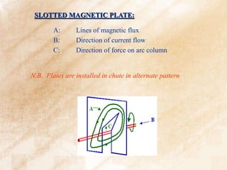
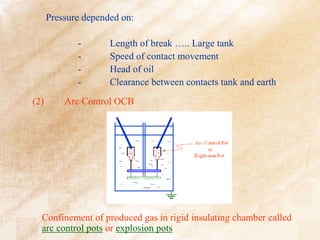
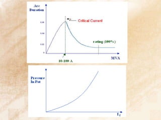
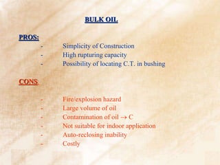
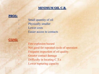
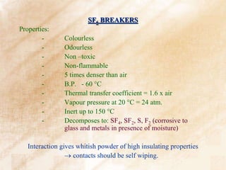
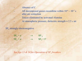
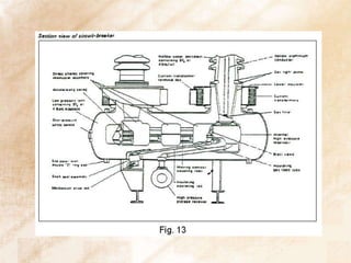
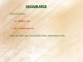
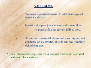
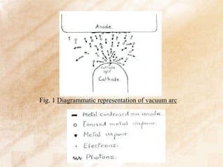
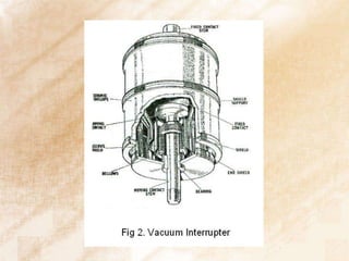
This document discusses switchgear technology, specifically focusing on different types of circuit breakers (CBs). It describes:
1. The basic physics of arcs in CBs and how they are controlled through insulating materials, arc chutes that confine and cool arcs, and contact arrangements.
2. How air circuit breakers (ACBs) and air blast CBs interrupt arcs naturally or through injected air, while oil circuit breakers (OCBs) rely on oil to cool arcs.
3. SF6 and vacuum breakers, which use insulating gases and high vacuum respectively to rapidly deionize arcs at current zero.
1. ECNG 3015
Industrial and Commercial Electrical Systems
Lecturer
Prof Chandrabhan Sharma
# 6
Switchgear Technology
2. SWITCHGEAR TECHNOLOGY
SWITCHGEAR
Contacts Theory of Conduction
(i) Metallic electrons
(ii) Electrolytic ions
(iii) Gas Discharge electrons and ions
Regions for electron flow are:
- Areas in metallic contact
- Areas Quasimetallic contact 20 Å
- Areas fritting of contact film thin enough to allow
dielectric breakdown.
3. PHYSICS OF ARCS IN C.B.
C.B. has two (2) stable conditions
(a) Close Ƶc 0
(b) Open Ƶc
Ƶc goes from 0 in cycles.
Too long time release of large energy
Too short switching overvoltages.
For AC interruption, switching is done at natural current zero.
4. INSULATING MATERIALS
* Can be solid, liquid or gaseous:
Liquid & Gaseous: Includes air, SF6, oil and vacuum
Dielectric Strength:
x 3 x 3
Air SF6 Oil Vacuum
SOLID DIELECTRICS:
Natural in Origin -: Mica, asbestos and slate
Derived from natural materials: Porcelain, paper and shellac varnishes
Newer materials : petrochemical derived, polymers, resins, films, plastics
5. Arc Extinction: Natural deionization of gases by cooling action.
Stretching Arc R
As R If and 0
i=0 when v=0
Rarc can be increased:
(1) Increasing arc length
(2) Cooling arc
(3) Splitting arc into several arcs
AIR CIRCUIT BREAKERS
6. ARC CHUTES:
Two (2) Types:
- Insulated plate
- Metal plate
Controlling force that direct arc into chute given by natural
electromagnetic and thermal forces of the arc.
* Strong magnetic field provided by:
(i) External iron cct around the arc energised by fault
current.
(ii) Internal iron cct in form of special shaped steel
plates.
7.
8. Arc Chutes:
Perform three (3) functions
- Confinement of arc
- Magnetic control
- Rapid cooling of arc gases
Arc Splitter:
9.
10. Three (3) stage contact arrangement:
(1) Main contact
(2) Intermediate contact
(3) Arcing contents
11. SLOTTED MAGNETIC PLATE:
A: Lines of magnetic flux
B: Direction of current flow
C: Direction of force on arc column
N.B. Plates are installed in chute in alternate pattern
12. Operation:
Interruption f (turbulence for cooling)
Dry compressed is an excellent dielectric.
Extinction occurs at 1st current zero.
High voltages
AIR BLAST C.B.
Types:
(1) Axial Blast
(2) Radial Blast
(3) Cross Blast
13. Factors influencing performance:
(a) Air Pressure:
Dielectric strength increases with increasing pressure,
i.e breaking capacity pressure at nozzle.
(b) Cct Severity
14. (c) Distance Between Contacts
(d) Contact material improvement (high B.P. material)
(e) Area of exit hole
(f) Resistance switching (shunt)
- Reduce RRRV and restriking voltage (Vc)
- Reduce transient voltage
- Improve uniformity of voltage sharing multibreak CB
15. PROS:
- No fire hazard
- Fast operation
- Suitable for rapid reclosing
- High rupturing capacity
- Low contact damage
- Easy access to contacts
CONS:
- Complete air system
- Complicated construction
- Specialized maintenance required
- Sensitive to RRRV
- Noisy
16. Shunt Resistors:
They are used for:
- Voltage grabbing
- Overvoltage suppression
- Reducing cct. severity
- Closing resistors for energizing long tx lines
17. OIL CIRCUIT BREAKER
Heat of arc immediately dissociates the surrounding oil into C and H2.
H2 has high heat conductivity; hence cooling of arc and contacts
Cooling so fast that re-ignition voltage is 5 – 10 times as for A.C.B.
Evolved gas:
H2 – 66% CH4 – 9%
C2H2 – 17% other – 8%
HIGHLY FLAMMABLE!!!!!!!
Volume Generated fn arc energy (Isc)
18. PROS:
- Oil is a spontaneous producer of H2
- Very good dielectric
- Very good thermal conductivity
CONS:
- Flammable
- H2 and oil can form an explosive mixture with air
- Carbon pollution of oil
See handout!
19. - No special Arc Extinction system
- Extinction due to turbulence and pressure
EVOLUTION OF OCB
(1) Plain Break
20. Confinement of produced gas in rigid insulating chamber called
arc control pots or explosion pots
(2) Arc Control OCB
Pressure depended on:
- Length of break ….. Large tank
- Speed of contact movement
- Head of oil
- Clearance between contacts tank and earth
21. (3) Minimum oil volume (Ref to Fig 9)
- Uses solid materials for insulating purposes and just
enough oil for arc quenching
- Oil tank is at system voltage hence ‘Live tank OCB’
nomenclature.
Three (3) types:
(i) Self blast type
(ii) External blast
(iii) Combination (i) and (ii)
22.
23.
24.
25.
26. BULK OIL
PROS:
- Simplicity of Construction
- High rupturing capacity
- Possibility of locating C.T. in bushing
CONS:
- Fire/explosion hazard
- Large volume of oil
- Contamination of oil C
- Not suitable for indoor application
- Auto-reclosing inability
- Costly
27. MINIMUM OIL C.B.
PROS:
- Small quantity of oil
- Physically smaller
- Lower costs
- Easier access to contacts
CONS:
- Fire/explosion hazard
- Not good for repeated cycle of operation
- Frequent inspection of oil quality
- Greater contact damage
- Difficulty in locating C.T.s
- Lower rupturing capacity
28. SF6 BREAKERS
Properties:
- Colourless
- Odourless
- Non –toxic
- Non-flammable
- 5 times denser than air
- B.P. - 60 C
- Thermal transfer coefficient = 1.6 x air
- Vapour pressure at 20 C = 24 atm.
- Inert up to 150 C
- Decomposes to: SF4, SF2, S, F2 (corrosive to
glass and metals in presence of moisture)
Interaction gives whitish powder of high insulating properties
contacts should be self wiping.
29. - Absence of C
- All decomposed gasses recombine within 10-6 – 10-7 s
after arc extinction
- Traces eliminated by activated Alumina
- At atmospheric pressure, dielectric strength 2.5 x air
SF6 strongly electronegative
SF6 + e SF-
6
SF6 + e SF5 + F-
See figs 13 & 14 for Operation of SF6 breakers
30.
31.
32. VACUUM ARCS
Two (2) Forms
(a) Diffuse Arc
(b) Constricted Arc
Once arc falls into constricted mode, interruption fails.
33. VACUUM C.B.
- Vacuum arc persists because of metal atoms ejected
from cathode spot.
- Intensity of vapour jets intensity of current flow
plasma falls as current falls to zero.
- At current zero metal atoms and ions migrate and
condense on electrodes, shields and walls rapidly
deionising gap.
* Total absence of charge carriers vacuum breaker has near ideal
withstand characteristics.
36. Applicable Properties of Vacuum
(i) Highest insulating strength known.
(ii) Interruption occurs at first current zero & dielectric
strength building up at rate 1000 x that of conventional
breakers.
(iii) At current zero, cathode spot extinguishes within 10-8 s
37. - The Diffuse arc has very high interrupting ability
- The Constricted arc has no interrupting ability
In order to ensure arc does not remain constricted, special
contacts have been designed.
(i) Spiral petal contact
(ii) Contrate contact
Depend for action on interaction of magnetic field of arc so
as to keep the arc in constant motion.
38.
39. Contact materials:
- Must not weld under fault conditions
- Must not chop on magnetizing current switching
- Must permit high dielectric recovery after interruption
- High conductivity
- Ease of manufacture
Used * Copper – Bismuth alloy
* Copper – chromium alloy
40. C. B. ratings:
- Rated V and I
- Rated frequency
- Breaking Capacity-: symmetrical and asymmetrical
- Making capacity
- Short-time current duration
- Operating duty.
41. ROUTINE TESTS (All C.B.)
1. High Voltage
2. Mechanical
3. Resistance tests (ohm meter)
4. For O.C.B. → oil testing