This document provides guidance on setting calculations for transformer differential protection. It discusses examining CT performance, calculating winding "tap" values, and determining pickup points for the 87T, 87H, and 87GD elements. Key steps include checking CT and relay ratings, selecting tap settings, setting the 87T minimum pickup and slope settings, setting harmonic restraint values, and setting the 87H unrestrained high set differential pickup and delay. The goal is to provide high-speed protection while avoiding misoperation during conditions like inrush current.


![Differential Protection Setting Calculations
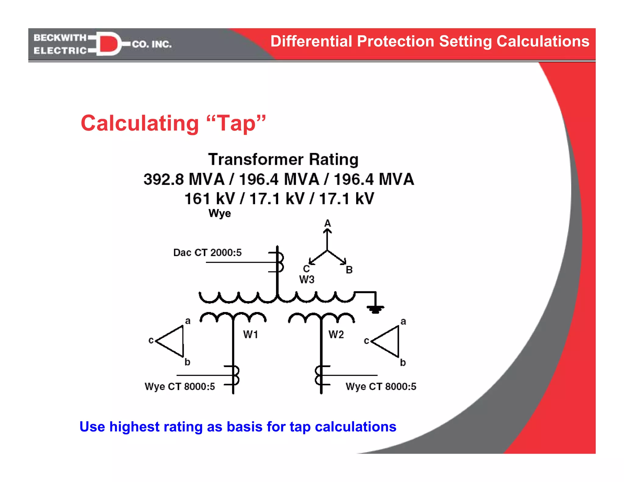
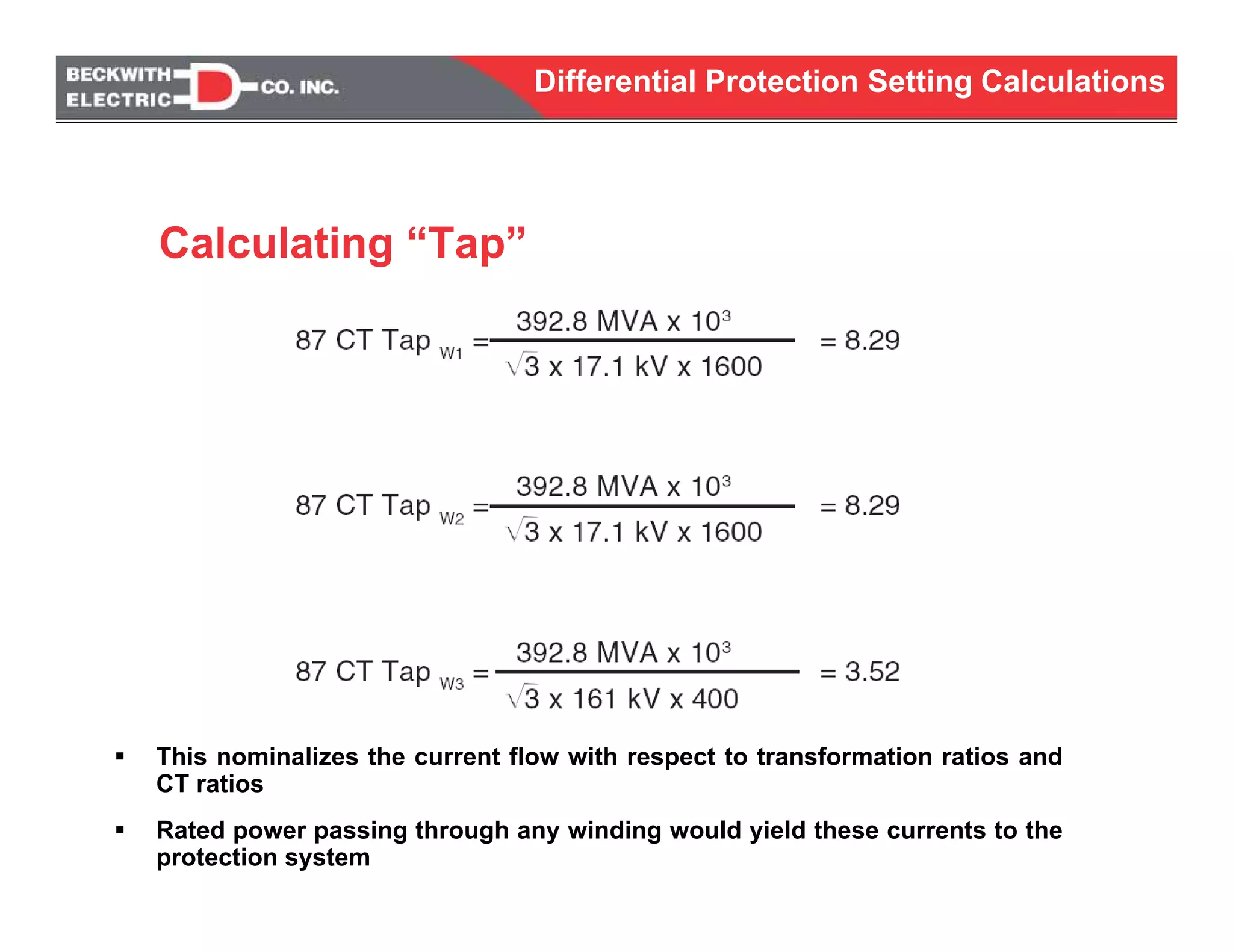
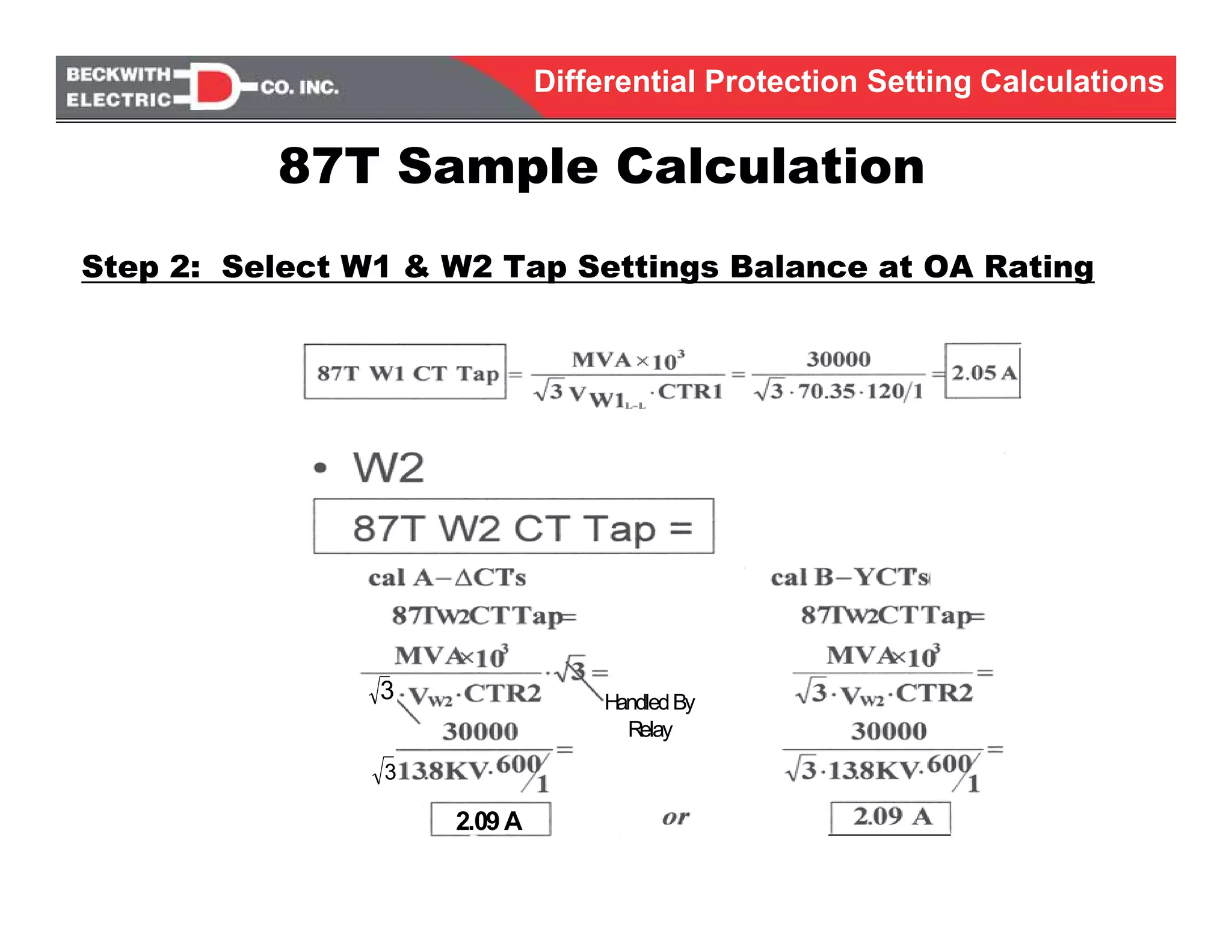
Used to determine current at rated transformer capacity
- Normally pick highest rating of multiple MVA rated
transformers
Allows “nominalization” of the transformer windings
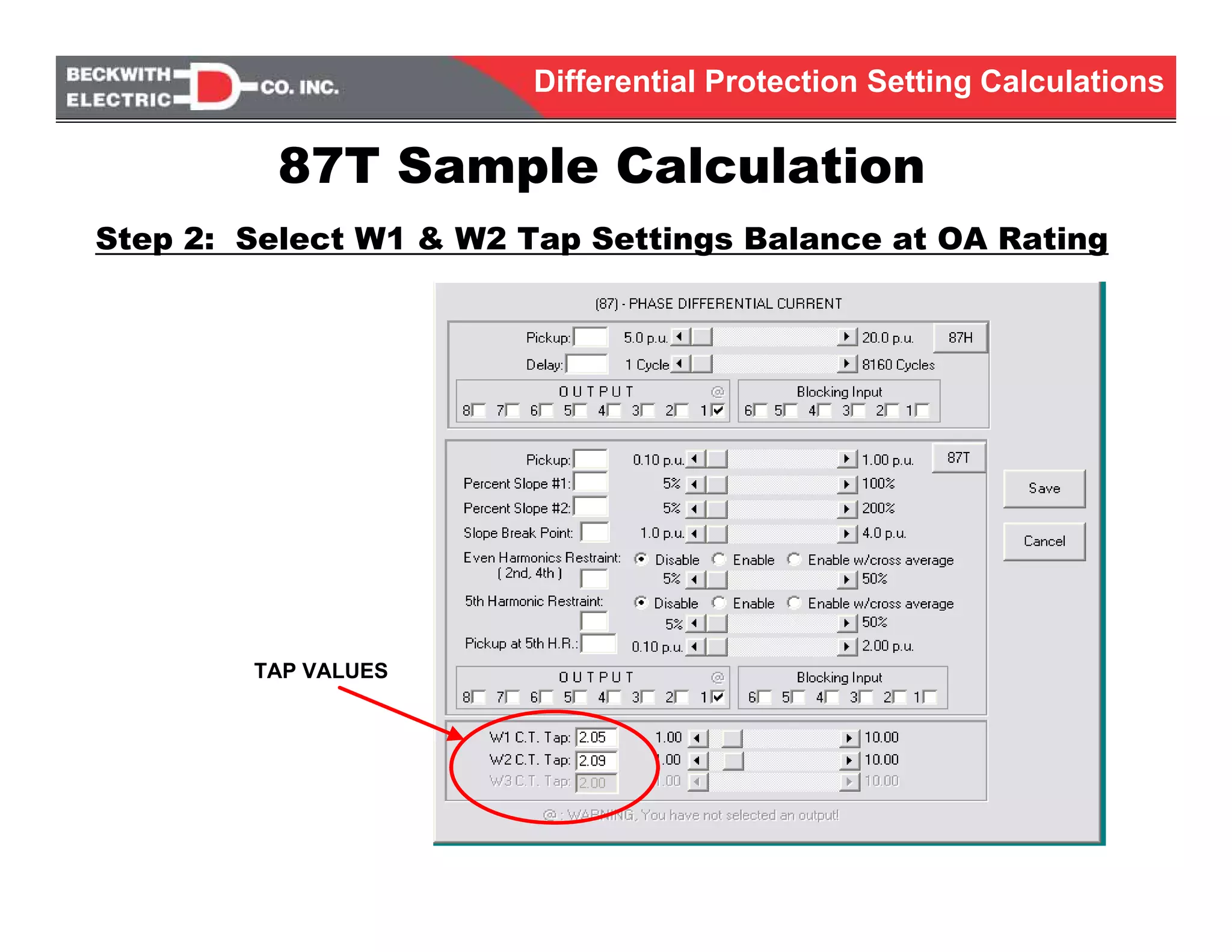
Used to obtain “tap” that is digitally set
Itap = VA / [√3 * VLL] * CTR
This accommodates:
- Transformer winding ratios
- CT ratios
Power-Current Conversion](https://image.slidesharecdn.com/transformerdifferentialprotection080710-160323223538/75/Transformer-differential-protection-15-2048.jpg)