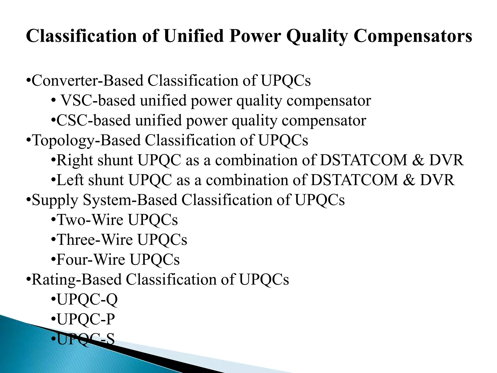
This document classifies unified power quality compensators (UPQCs) in four ways:
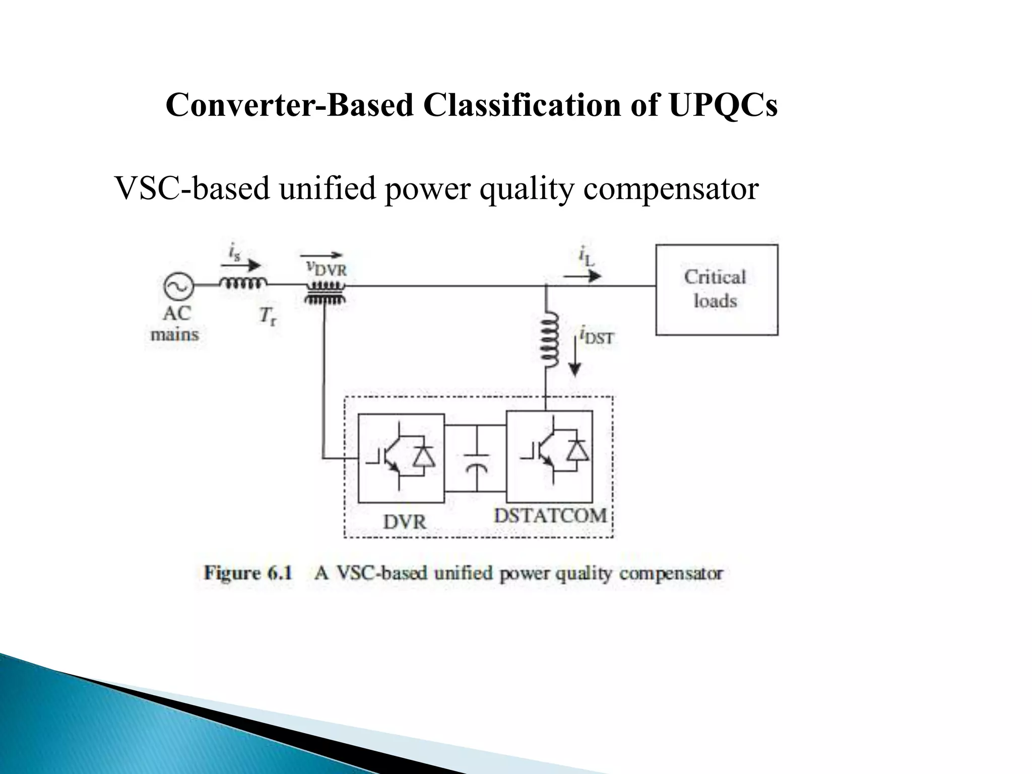
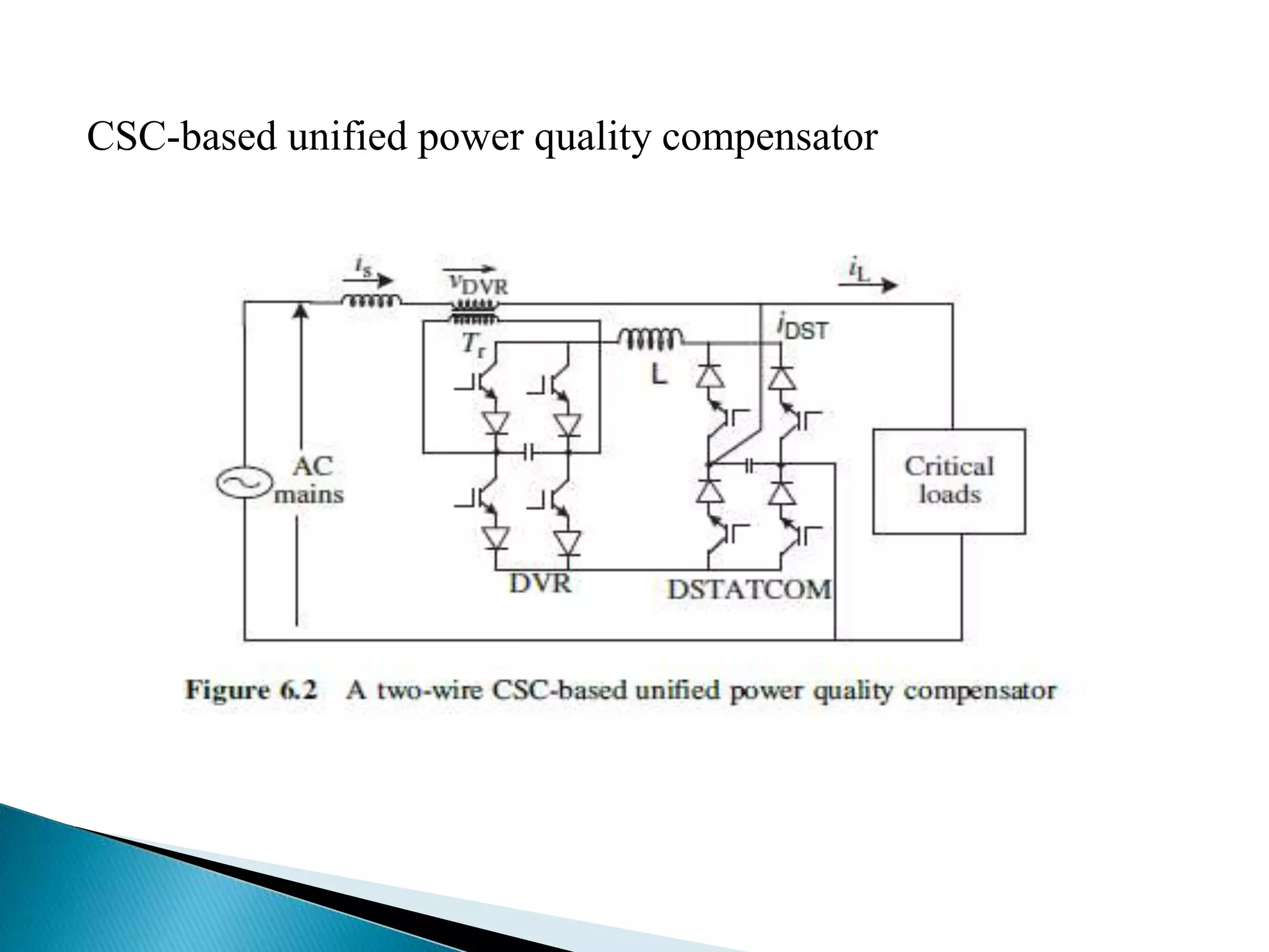
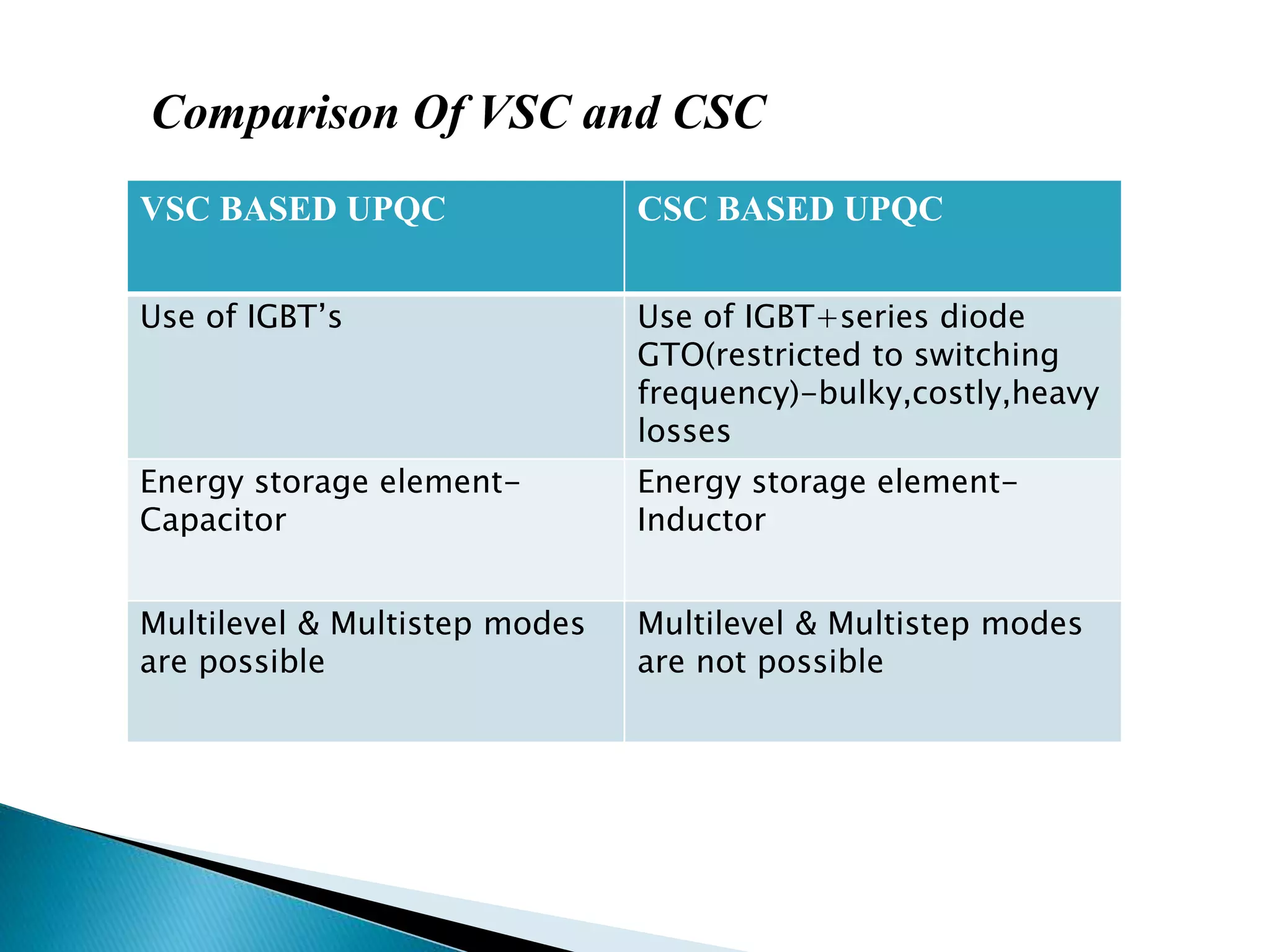
1. By converter - either voltage source converter (VSC) based or current source converter (CSC) based, with VSC using IGBTs and allowing multilevel operation while CSC uses inductors for energy storage.
2. By topology - as a combination of DSTATCOM and DVR connected either in right or left shunt configuration to regulate voltage and eliminate harmonics.
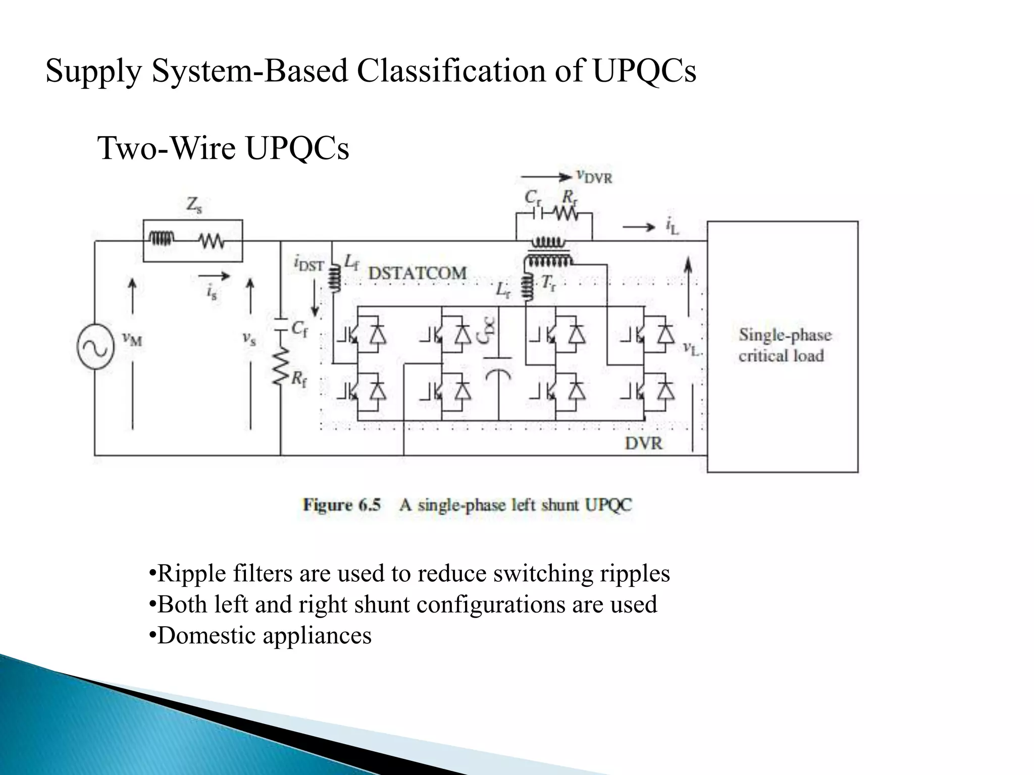
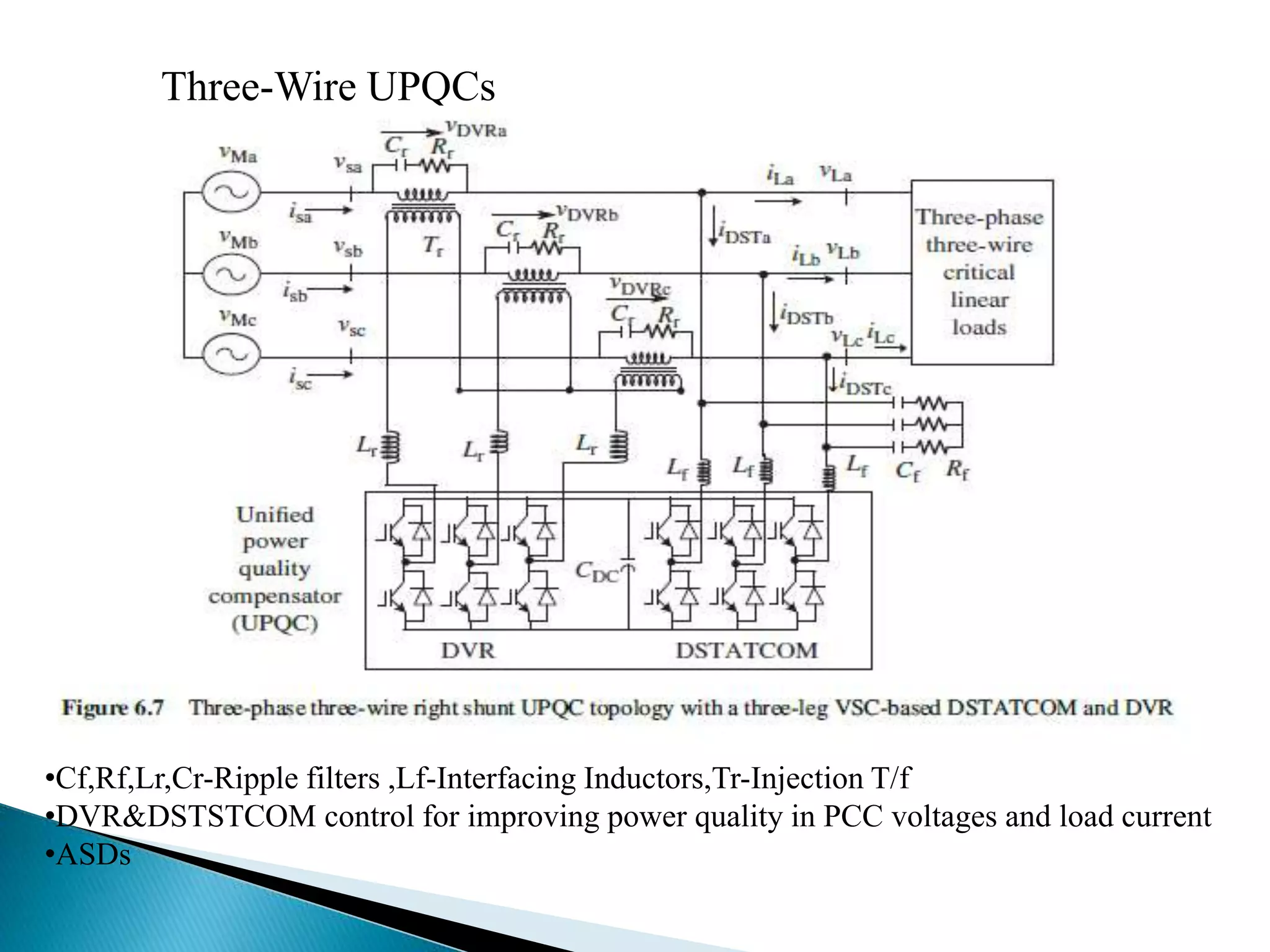
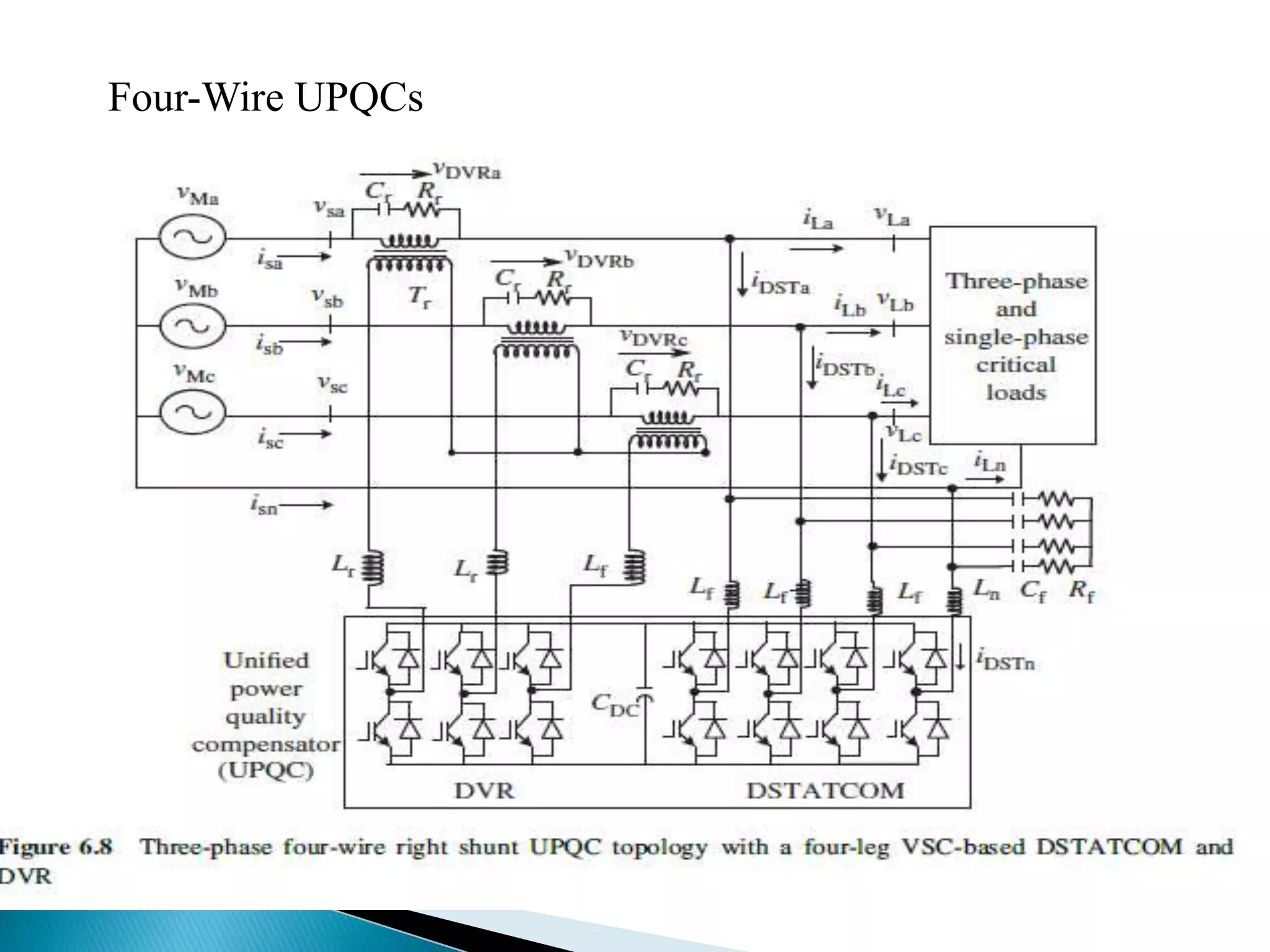
3. By supply system - as two-wire, three-wire, or four-wire UPQCs to compensate different applications like domestic appliances or adjustable speed drives.
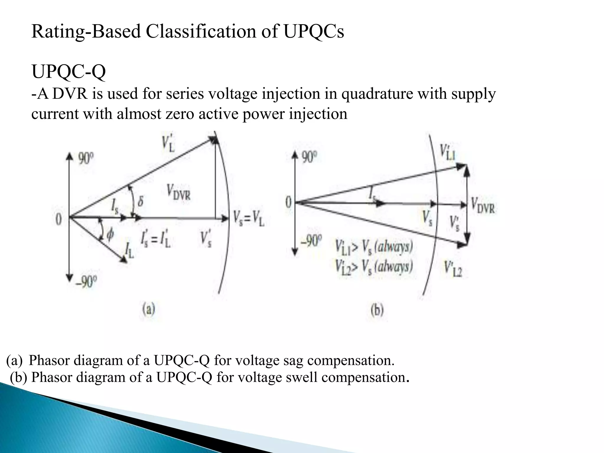
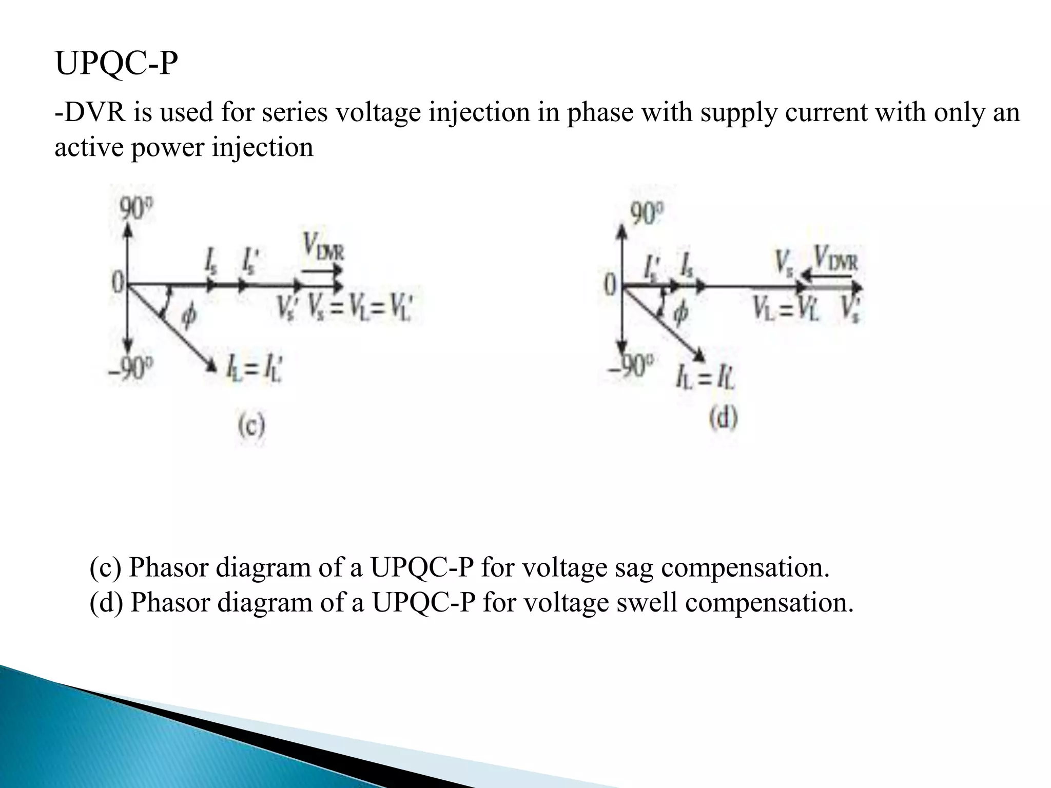
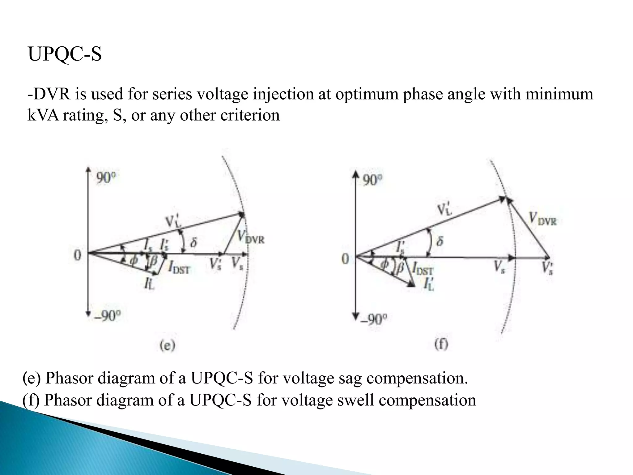
4. By rating - as UPQC-Q injecting