Download as PDF, PPTX


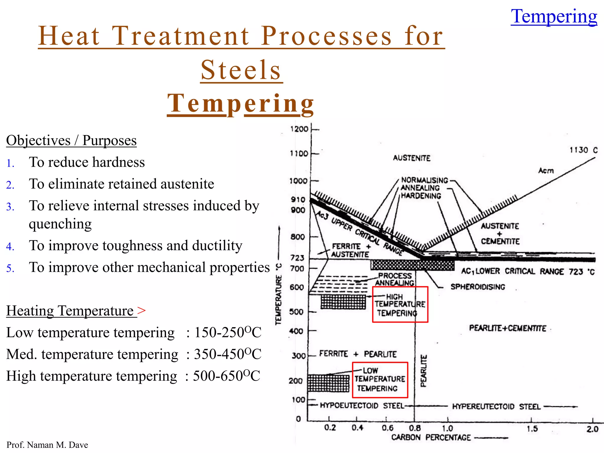


1. The document discusses various heat treatment processes for steels including annealing, normalizing, and hardening. 2. Annealing involves heating and slow cooling to soften steel by refining grain structure. Types include stress relief, spheroidizing, and full annealing. 3. Normalizing refines grain size by heating above the critical temperature and slow cooling in air. 4. Hardening increases hardness and wear resistance by heating and quenching in water or oil to form martensite.