Download as PDF, PPTX


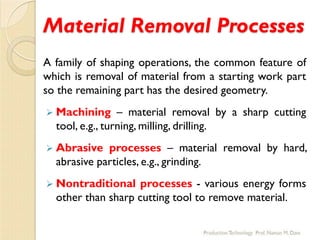


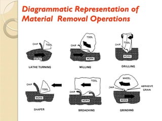
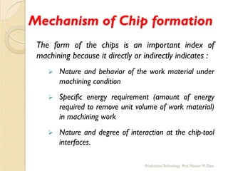


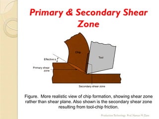


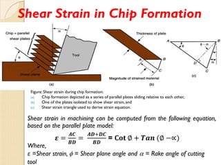


The document presents a comprehensive overview of manufacturing and metal cutting processes, emphasizing the definition of manufacturing, the importance of machining, and the mechanisms involved in material removal. It details various machining processes, their advantages and disadvantages, and elaborates on the mechanics of chip formation and the forces acting on the chip during cutting operations. Additionally, the document references several authoritative texts that provide further insights into manufacturing technologies.