Downloaded 286 times

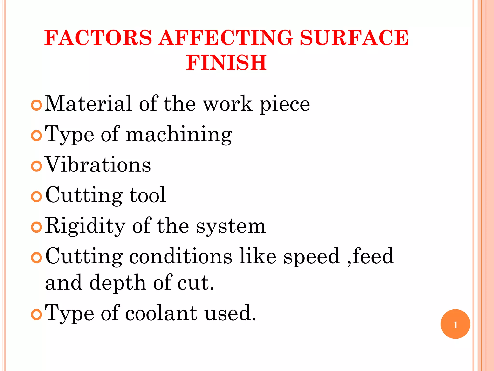
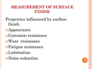
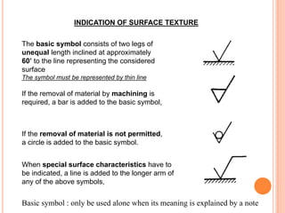
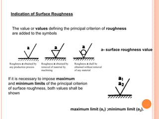
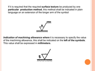
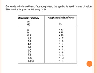
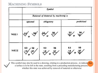
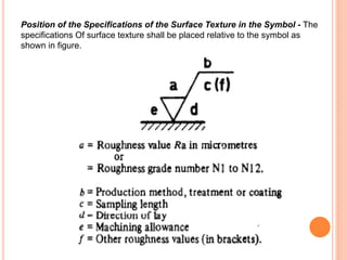

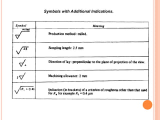
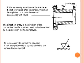
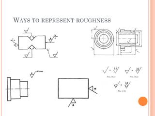
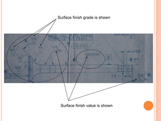
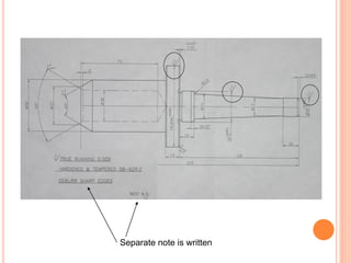
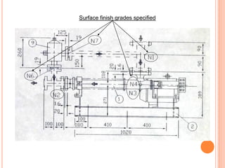
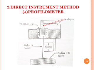
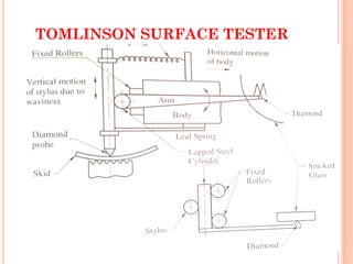
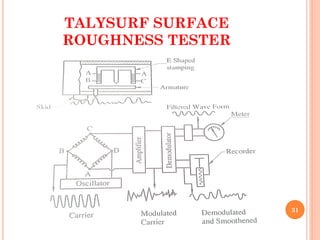
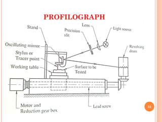
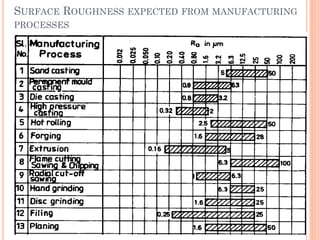

The document discusses factors that affect surface finish, methods for measuring surface finish, and ways to represent surface roughness specifications. It describes that the material, machining type, tooling, and cutting conditions can influence surface finish. Methods for measuring finish include comparison to standards, using a profilometer, profilograph, or other instruments. Surface roughness can be specified via standard grades, numerical values, or symbols added to drawings.


![Ppt Fits Tolerances[1]](https://cdn.slidesharecdn.com/ss_thumbnails/pptfitstolerances1-091107045206-phpapp01-thumbnail.jpg?width=640&height=640&fit=bounds)


