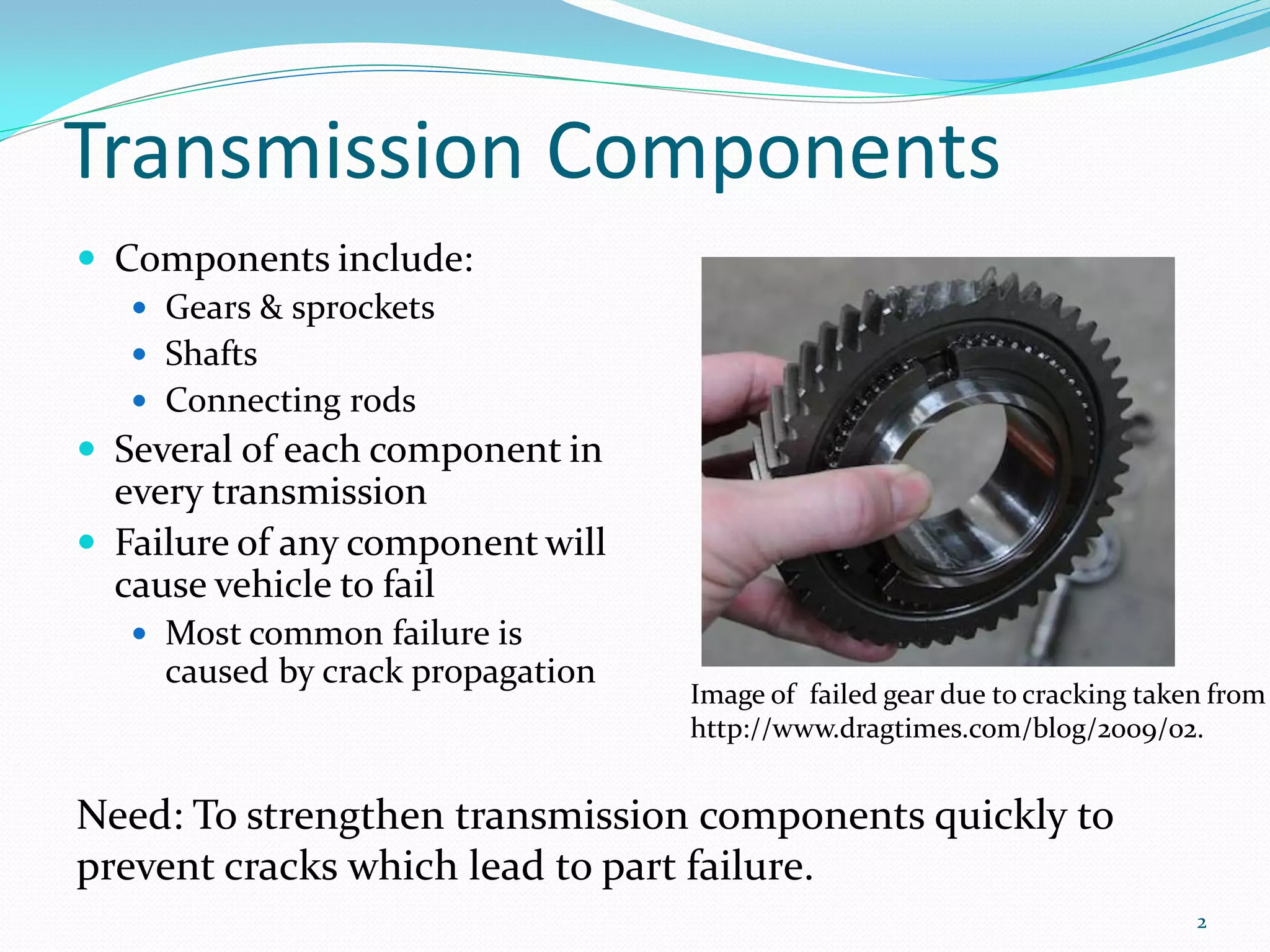
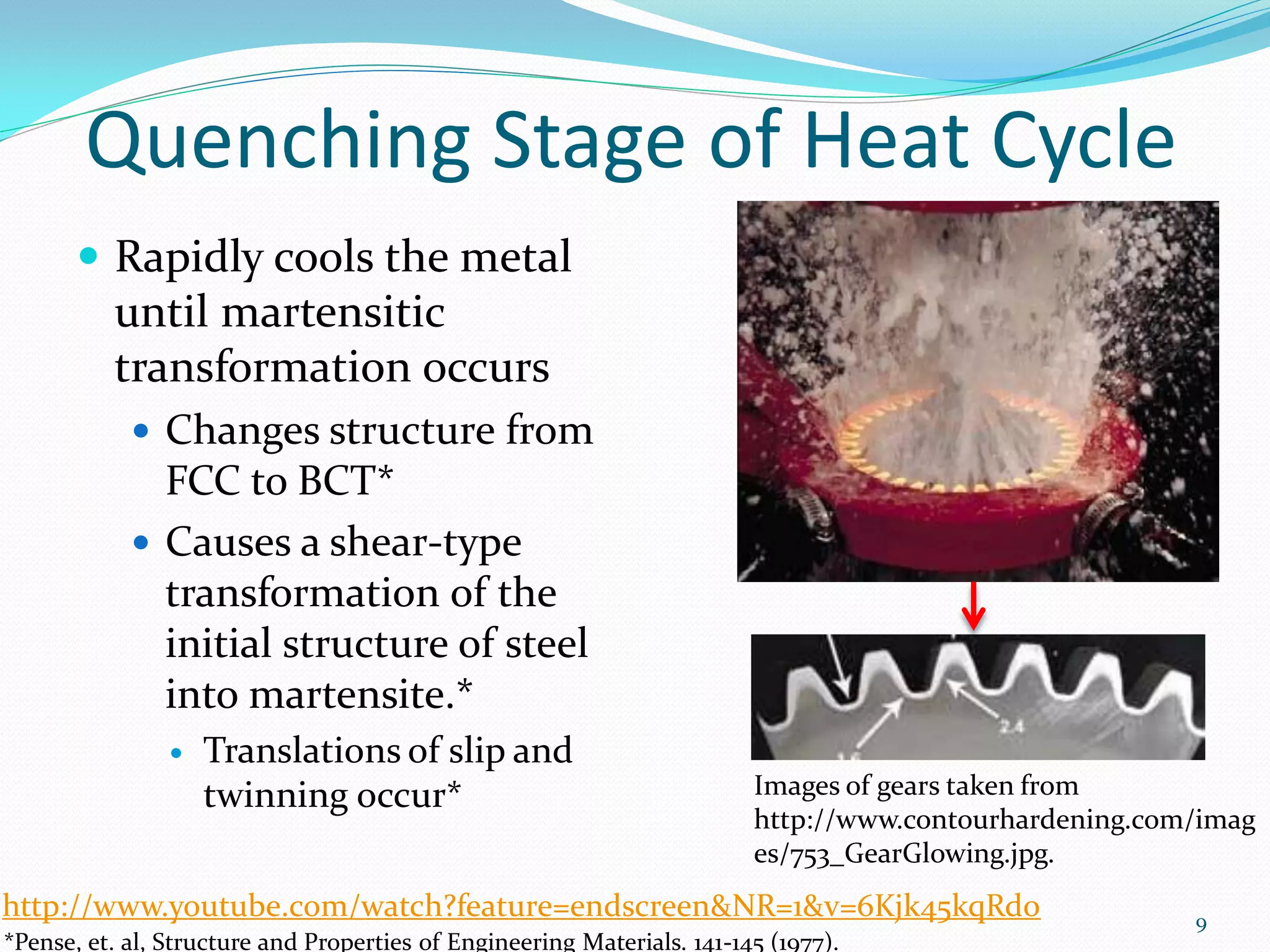
Induction hardening is an efficient surface hardening process that uses electromagnetic induction to generate eddy currents and rapidly heat metal components. It produces a martensitic microstructure upon quenching that increases hardness, strength, and wear resistance while minimizing distortion compared to traditional furnace treatments. Induction hardening takes less than a minute, whereas nitriding and carburizing can take hours, and it induces higher compressive residual stresses in the surface.
![Popular Hardening Treatments*
Flame hardening (~50 HRC) (a) (b)
Only for gray cast iron
Anneals core material during process
Nitriding (~69 HRC)
Uses ammonia or cyanide salt baths Images of gear teeth hardened by (a)
nitriding and (b) carburizing taken from
Depth of 1 mm
http://www.gearsolutions.com/media//uplo
Roughly 4 hours per work piece ads/assets//PDF/Articles/Jan_10/0110_Boeing
.pdf
Carburizing (~50 HRC)
Used on low carbon content steel
(<0.2%C) Need more efficient
Depth up to 6 mm process with required
Typically 12-72 hrs. per work piece product properties with
shorter process time!
3
*Davis, et. al, Surface Engineering of Cast Irons, Surface Engineering, ASM Handbook [5] 683-700 (1994)](https://image.slidesharecdn.com/inductionhardeningashleylane-1347397922344-phpapp01-120911161328-phpapp01/75/Induction-Hardening-3-2048.jpg)
![Why Choose Induction?
Produces ideal properties
Hardness (~67 HRC)
Strength and wear resistance of part
Has much faster heating rate than traditional furnace
treatments
Provides for more control over outcome
Less distortion of work piece*
Warpage is roughly 0.03mm compared to 0.3mm from furnace treatments*
Heating can be localized for surface hardening
Allows the core metal to be unaffected
Creates higher residual stresses
4
*Rudnev, Simulation of Induction Heat Treating, Metals Process Simulation, ASM Handbook, [22B]501–546 (2009).](https://image.slidesharecdn.com/inductionhardeningashleylane-1347397922344-phpapp01-120911161328-phpapp01/75/Induction-Hardening-4-2048.jpg)
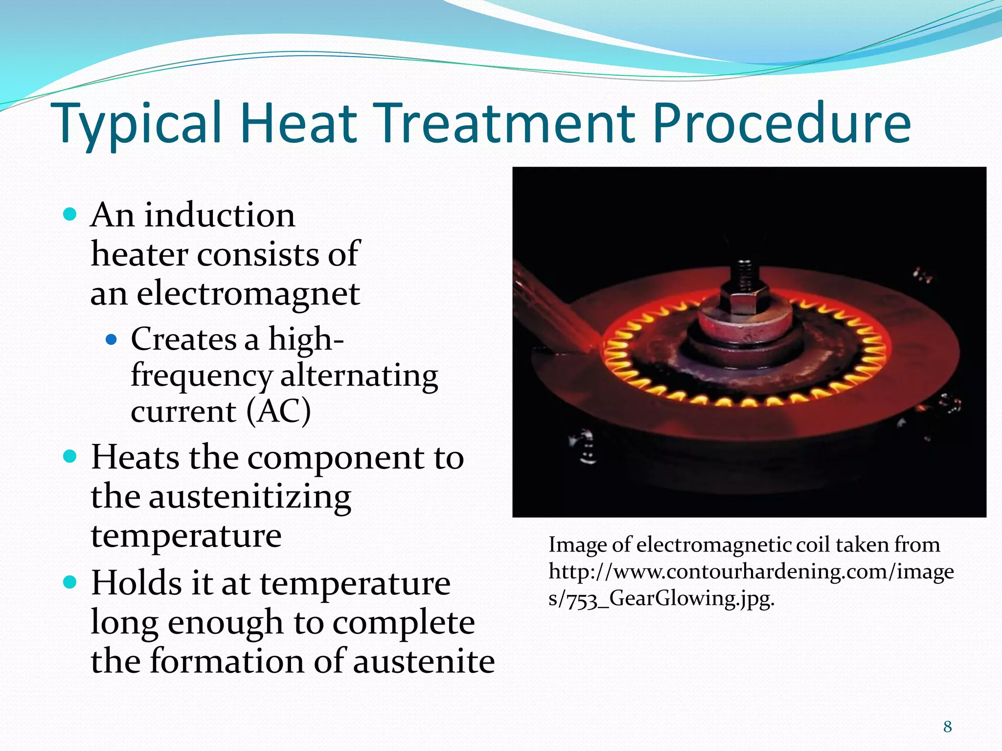
![Induction Hardening
Heat treatment used for metal
(typically steel)
Uses electromagnetic induction*
Eddy currents are generated in
metal
Resistive heating is proportional to
resistance in metal and currents
produced
Hardening may be done on the
surface or throughout entire work Image of hardened gear teeth taken
piece from
http://www.ersengine.com/gains-
Utilizes localized heating
ground-through-advances-in-
Does not affect properties of the technology/.
part as a whole
5
*Rudnev, Simulation of Induction Heat Treating, Metals Process Simulation, ASM Handbook, [22B]501–546 (2009).](https://image.slidesharecdn.com/inductionhardeningashleylane-1347397922344-phpapp01-120911161328-phpapp01/75/Induction-Hardening-5-2048.jpg)
![Currents and Magnetic Field
Eddy currents
Current induced in conductors
when exposed to a
changing magnetic field
Due to variations of the field with
time
Generates resistive heating in metal
Can reaustenitize metal in 0.5 s*
Induced as result of Faraday’s law
of induction*
𝑑Φ
𝑒 = −𝑁 Image of currents and magnetic field
𝑑𝑡 induced during hardening process.*
e =induced voltage
N=number of coil turns
Φ= magnetic field
6
*Hassell, et. al, Induction Heat Treating of Steel, Heat Treating, ASM Handbook [4] 164–202 (1991).](https://image.slidesharecdn.com/inductionhardeningashleylane-1347397922344-phpapp01-120911161328-phpapp01/75/Induction-Hardening-6-2048.jpg)
![Electrical Properties of Steel
Only adjustable parameter is the
frequency
High frequencies are used for
surface hardening
Frequency (kHz)
Lower frequencies are used for
through-hardening
ρ
𝑑=
πμ0 μ f
d=depth of hardening
ρ= resistivity Diameter (mm)
μ0= 4π×10−7 V·s/(A·m) (magnetic permeability of vacuum)
μ =magnetic permeability of part Plot of diameter versus frequency in
f=frequency of magnetic field plain carbon steel.*
7
*Hassell, et. al, Induction Heat Treating of Steel, Heat Treating, ASM Handbook [4] 164–202 (1991).](https://image.slidesharecdn.com/inductionhardeningashleylane-1347397922344-phpapp01-120911161328-phpapp01/75/Induction-Hardening-7-2048.jpg)
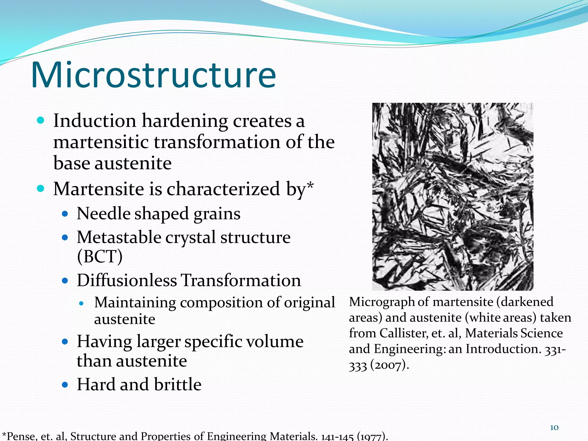
![Microstructural Relations
Hardness of austenitized
parts depends mainly on
chemical composition
and quench medium*
Desired Microstructures
for reaustenization*
Finer bainite and
martensite> pearlite>
Effect of carbon on hardness in plain carbon
spheroidite steels for (A) induction hardening, (B) furnace
hardening with water quench and (C) furnace
hardening with water quench and temper. The
quenched-and-tempered steels were treated in
liquid nitrogen following water quenching
prior to tempering at 100 °C for 2 hrs.*
11
*Hassell, et. al, Induction Heat Treating of Steel, Heat Treating, ASM Handbook [4] 164–202 (1991).](https://image.slidesharecdn.com/inductionhardeningashleylane-1347397922344-phpapp01-120911161328-phpapp01/75/Induction-Hardening-11-2048.jpg)
![Induced Stresses
Treatment induces compressive
stresses at surface (>205 Mpa)*
Surface has volume expansion
Non-treated core remains
unchanged
Martensite retains residual
stresses**
Typical hardness and residual stress profile of
Image of gear teeth being heated taken from
induced-hardened steels using general
http://www.ersengine.com/gains-ground-through-
dissection method. **
advances-in-technology/.
*Sinha, et. al, Defects and Distortion in Heat-Treated Parts, Heat Treating, ASM Handbook [4] 601-619 (1991). 12
**Davis, et. al, Surface Engineering of Cast Irons, Surface Engineering, ASM Handbook [5] 683-700 (1994)](https://image.slidesharecdn.com/inductionhardeningashleylane-1347397922344-phpapp01-120911161328-phpapp01/75/Induction-Hardening-12-2048.jpg)
![Maximum Residual Stresses in
Surface-treated Steel*
Heat treatment Residual Stress (MPa)
Carburized and quenched 340
Nitrided to case depth of about 0.5
600
mm (0.02 in.)
Induction hardened, untempered 1000
Stress measurements taken at 0.05mm from surface
13
*Sinha, et. al, Defects and Distortion in Heat-Treated Parts, Heat Treating, ASM Handbook [4] 601-619 (1991).](https://image.slidesharecdn.com/inductionhardeningashleylane-1347397922344-phpapp01-120911161328-phpapp01/75/Induction-Hardening-13-2048.jpg)
![Review of Surface Hardening *
Induction hardening (~67 HRC) (a)
(b)
Can be used on any type of steel
Utilizes localized heating
Has clean transition pattern
Process takes less than 1 minute
Nitriding (~69 HRC) (c)
Uses ammonia or cyanide salt baths
Depth of 1 mm
Roughly 4 hours per work piece
Carburizing (~50 HRC)
Images of gear teeth hardened by (a)
Used on low carbon content steel nitriding (b) carburizing and (c) induction
(<0.2%C) hardening found at
http://www.gearsolutions.com/media//uplo
Depth up to 6 mm
ads/assets//PDF/Articles/Jan_10/0110_Boeing
Typically 12-72 hrs. per work piece .pdf
14
*Davis, et. al, Surface Engineering of Cast Irons, Surface Engineering, ASM Handbook [5] 683-700 (1994)](https://image.slidesharecdn.com/inductionhardeningashleylane-1347397922344-phpapp01-120911161328-phpapp01/75/Induction-Hardening-14-2048.jpg)