Downloaded 410 times


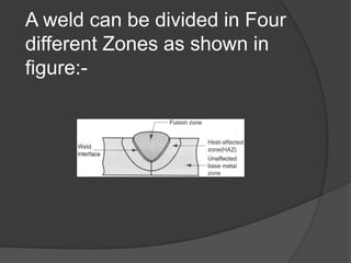

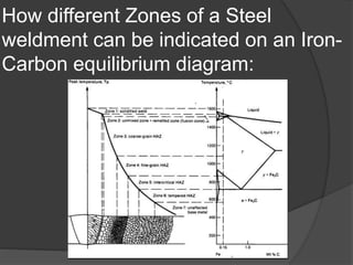


This document discusses welding defects and their causes. It outlines the four zones in a welded joint and how they appear on an iron-carbon phase diagram. The zones are the fusion zone, weld interface zone, heat affected zone, and base metal. Solidification can be epitaxial or non-epitaxial depending on whether filler metal is used. Common welding defects include cracks, porosity, inclusions, incomplete fusion, imperfect shape, and residual stresses. Various defect types like longitudinal cracks and underbead cracks are described in more detail.


