The document describes the fetch-execute cycle of a computer processor. It involves:
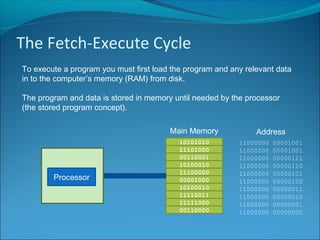
1) Loading the program and data into memory from disk.
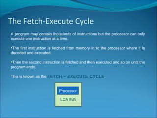
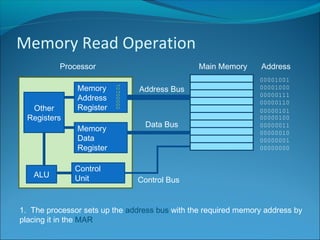
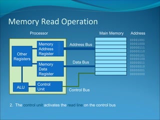
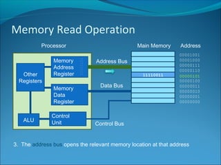
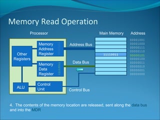
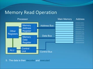
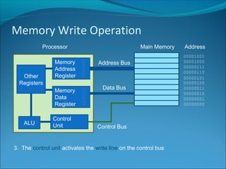
2) Fetching instructions one at a time from memory into the processor to be decoded and executed.
3) Repeating the fetch-execute cycle until the entire program is completed.