Downloaded 10 times


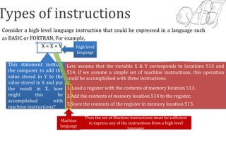
![Instruction cycles and subcycles (fetch and execute etc)
1
2
3
4
5
6
ALU
+1
Instruction
decoder
Program
counter Memory
Address
Register
Memory Buffer
Register
Current
Instruction
Register
Op-code Operand
Accumulator
Data Bus
Address
Bus
Main Memory
0000 0000 0000 0011
0101 0000 0000 0110
FETCH
MAR ← [PC]
0000 0000 0000 0011
PC ← [PC] + 1
0000 0000 0000 0100
MBR ← memory
content
0101 0000 0000 0110
0101 0000 0000 0110
CIR ← [MBR]
Decode Unit
Opcode operand Instruction
……….. ………..
0101 Address load
………... …………
0000 0000 0110
0100 0000 0110 0101
0100 0000 0110 0101](https://image.slidesharecdn.com/1instruction-171004062749/85/instruction-7-320.jpg)

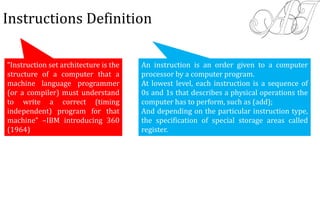
![Continued….
4. Load MDR from the memory bus
3. Wait for the MFC response from the memory
As an example of a read operation, consider the instruction Move
(R1), R2. Following are the steps required to execute this
instruction are:
1. MAR → [R1]
2. Start a Read operation on the memory bus
5. [R2]→MDR
•The response time of each memory access varies (cache miss,
memory-mapped I/O,…).
•To accommodate this, the processor waits until it receives an
indication that the requested operation has been completed
(Memory-Function-Completed, MFC).](https://image.slidesharecdn.com/1instruction-171004062749/85/instruction-12-320.jpg)
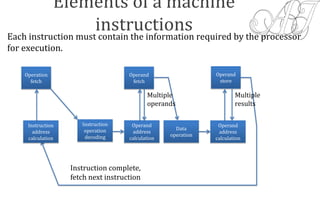
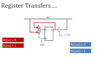
![Timing
Assume MAR
is always available
on the address lines
of the memory bus.
1Step
Clock
MARin
MAR ← [R1]
Read
2
Will cause the bus interface circuit to send
a read command, MR on the bus
Address
MR
MDRinE
Data
MFC
3
MDRout
3. MDRout, R2in
1. R1out,MARin,
Read
2. MDRinE, WMFC
N.B.- here we
have reduced
the steps, now
these are three
only.](https://image.slidesharecdn.com/1instruction-171004062749/85/instruction-13-320.jpg)


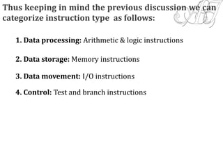
The document discusses the instruction set architecture, which is crucial for machine language programming, outlining various elements of machine instructions, including operation codes and operand references. It categorizes instruction types into data processing, storage, movement, and control, illustrating how high-level programming statements translate into machine instructions. Additionally, it explores instruction cycles, register transfers, and memory fetching processes, emphasizing the operational flow and timing considerations in executing machine instructions.