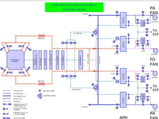
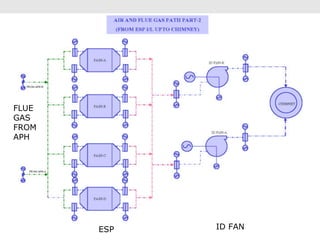
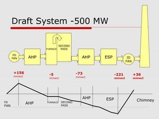
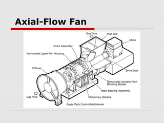
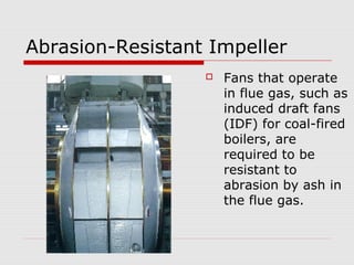
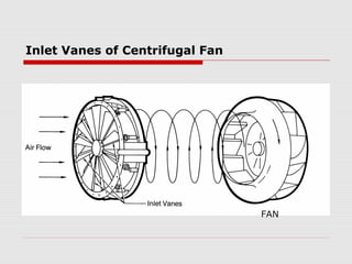
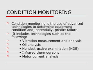
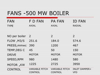
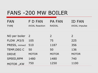
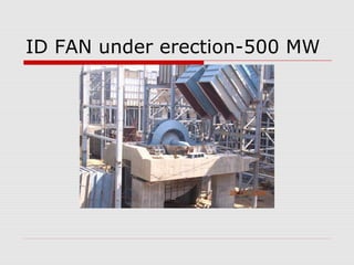
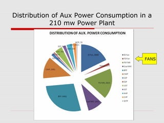
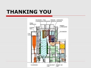
FANS IN THERMAL POWER
        PLANTS


     SHIVAJI CHOUDHURY
Fan
   A fan can be considered a mechanical device that
    moves a volume of fluid such as air, gas, or vapor
    through a pressure driven flow.
    Large capacity fan units typically consist of a bladed,
    rotating impeller enclosed in a stationary casing.
    The rotor system causes the motion of the air/gas
    and the casing directs the output flow.
    The rotor can be powered through a driver such as a
    motor, a turbine driver, or a fluid-driver.
Fan Components
Types of Fans
    A fan is classified by the
    direction of its flow
    through the bladed
    passages of the impeller.
   A centrifugal fan
    moves the air
    perpendicular to the
    rotational axis of the
    impeller .
   an axial fan moves the
    air parallel to the
    rotational axis of the
    impeller.
Centrifugal (radial) Fan Blade Types
Function of Fans in Boiler

    Supply air required for combustion
    Remove products of combustion
    Deliver fuel to the burners
    Circulate the gases for better heat
    transfer
Types of Power Plant Fans
There are four main types of fans used
  in fossil power plants.
  Forced draft fans,
 Induced draft fans,

  Primary air fans,
 Gas-recirculation fans.
Draft Fans
      Draft fans are generally responsible
    for maintaining the flow of gases
    through the boiler.
       A balanced draft system uses both a
    forced draft fan at the inlet of the
    system and an induced draft fan at the
    outlet of the boiler system.
BOILER

       Boiler drum
                                   Reheater
                                      Final Super
 Platen Super                         heater
 heater                               LTSH
                                       Economizer
                                                    Coal bunker
               Wind Box
                      Secondary
                                     PA duct
                      air duct
         Furnace
                                  Flue gas
                         APH      duct               Coal feeder


                       F D Fan    P A Fan
                                                          Coal
                                                          Pulverizer
Forced Draft Fans

   Forced draft fans (FD) supply the air
    necessary for fuel combustion by pushing the
    air through the combustion air supply system
    and into the furnace.
    These fans are typically the most efficient
    fans in the power plant because they have
    the cleanest operating environment .
    Typically, these fans are centrifugal fans
    utilizing radial airfoil blading or variable pitch
    axial fans.
Induced Draft Fans
   Induced draft fans (ID) are placed at the outlet of the
    boiler system and exhaust all gaseous combustion
    products, or flue gas, from the boiler by creating a
    negative pressure or suction within the furnace.
    These fans handle hot flue gas, they are generally
    more susceptible to erosion and corrosion even with
    particulate removal equipment (ESP).
   If greater wear resistance is necessary, a modified
    radial, forward-curved, or backward-inclined blading
    can be used at the expense of efficiency loss.
Primary air fans
   Primary air fans (PA) are high pressure fans used to
    supply the air for the transportation of coal directly from
    the pulverizer to the furnace .
   These fans provide a positive pressure upstream of
    the coal pulverizer and handle relatively clean air .
    A PA fan upstream from the pulverizer, or a “cold” PA
    fan, pushes the coal/air mixture through the
    pulverizer and is most commonly used.
    Cold PA fans typically are airfoil centrifugal fans or
    multi-stage axial fans similar to FD fans.
Gas Recirculation Fans
   Gas-recirculation fans are used to control steam
    temperature, furnace heat absorption, and slagging of
    heating surfaces.
    These fans extract gas from the economizer outlet
    and the pre-heater inlet and then discharge the gas
    either to the bottom of the furnace for steam
    temperature control or to various locations in the
    furnace.
   The duty cycle of a gas recirculation fan is very
    stringent due to heavy dust loads and extreme
    temperature excursions.
    Straight or modified radials or forward curved,
    backwardly inclined centrifugal wheels are appropriate
    for gas-recirculation fans.
PA
FAN


 TO
 ESP


FD
FAN


 TO
 ESP


PA
FLUE
GAS
FROM
APH


       ESP   ID FAN
Draft System -500 MW

                                SECOND
                      FURNACE    PASS

       FD
      FAN       AHP                          AHP   ESP            ID
                                                                 FAN


       +156                               -73
       mmwcl
                        -5                               -221          +36
                        mmwcl             mmwcl          mmwcl         mmwcl


                                             AHP   ESP
                                 SECOND
                                                                        Chimney
FD             AHP    FURNACE
                                 PASS
FAN
Axial-Flow Fan
Airfoil-Blade Centrifugal Fan
Damage Mechanisms

    Most common damage mechanisms
    associated with power plant fans
    failure are :
    Erosion,
    Corrosion,
    Vibration
    which are responsible for serious and
    costly maintenance.
Erosion
   One of the most common damage
    mechanisms associated with power plant
    fan failure is erosion, which is
    responsible for serious and costly
    maintenance.
   The rate of erosion depends on
    suspended particles / fly ash, in the flue
    gas.
EFFECT OF BLADE TYPE ON EROSION
RESISTANCE AND EFFICIENCY
BLADE TYPE            TYPICAL MAX STATIC TOLERANCE TO
                      EFFICIENCY ( %)    EROSIVE
                                         ENVIROMEMT
RADIAL
                      70                HIGH

RADIAL TIP
                      80                MEDIUM TO
                                        HIGH
BACKWARDLY INCLINED
SOLID                 85                MEDIUM

AIRFOIL
                      90                LOW
Resistant to Erosion

   The rate of erosion experienced by fans used in
    harsh applications is often controlled by the use
    of repairable liners, replaceable liners, or
    renewable coatings.
    Reducing fan speed and selecting a fan blade
    type that is more resistant to erosion will slow
    down the abrasive wall thinning experienced by
    fan unit surface.
Abrasion-Resistant Impeller
                     Fans that operate
                      in flue gas, such as
                      induced draft fans
                      (IDF) for coal-fired
                      boilers, are
                      required to be
                      resistant to
                      abrasion by ash in
                      the flue gas.
CORROSION
   The following list is the most common types of
    corrosion problems found in boiler power
    plants.
   •   Erosion corrosion
   •   Crevice corrosion
   •   Galvanic corrosion
   •   Pitting
   •   General corrosion (wastage)
   •   Differential Oxygenation
   •   Biological corrosion
   •   Intergranular corrosion
Vibration
    Possible reasons as to why vibration
    occurs in fan units are listed below.
   •   Improper balancing
   •   Loose components
   •   Worn/damaged/cracking of fan parts
   •   Improper Lubrication
   •   Improper clearance of moving parts.
   •   Excitation of a resonant frequency
   •   Corrosion, erosion, high/low cycle fatigue effects
   •   Misalignment or bent shaft
   •   Improperly designed or deteriorated foundations
   •   Build-up of material on the rotor
Output Air Flow Control

   A centrifugal fan utilizing inlet vanes
    controls the airflow .
    Most axial fans are operated by
    variable pitch axial blades, .
   A fan that is run with a variable speed
    motor can adjust the speed to control
    the output flow properties .
Inlet Vanes of Centrifugal Fan


                                 FAN
Variable Airfoil Blading of an
Axial-flow Fan
CONDITION MONITORING

   Condition monitoring is the use of advanced
    technologies to determine equipment
    condition and, potentially, predict failure.
    It includes technologies such as the
    following:
         • Vibration measurement and analysis
         • Oil analysis
         • Nondestructive examination (NDE)
         • Infrared thermography
         • Motor current analysis
STARTUP PROCEDURES OF DRAFT FANS


   The startup procedures, in addition
    to the controls and interlocks,
    should follow the requirements of
    NFPA 85.
FANS -500 MW BOILER
FAN             F D FAN          PA FAN           ID FAN
TYPE            AXIAL            AXIAL            RADIAL


NO per boiler   2                2                2
FLOW ,M3/S      251.6            184.0            574.6
PRESS,mmwc 390                   1200             467
TEMP,DEG C      45               50               150
DRIVE           MOTOR            MOTOR            MOTOR
SPEED,RPM       980              1480             580
MOTOR ,KW       1225             2725             3950
CONTROL         VARIABLE PITCH   VARIABLE PITCH   INLET DAMPER+
                CONTROL          CONTROL          VFD
FANS -200 MW BOILER
FAN             F D FAN          PA FAN   ID FAN
TYPE            AXIAL Reaction   RADIAL   AXIAL impulse


NO per boiler   2                2        2
FLOW ,M3/S      105              75       225
PRESS, mmwcl    510              1187     356
TEMP,DEG C      50               50       136
DRIVE           MOTOR            MOTOR    MOTOR
SPEED,RPM       1480             1480     740
MOTOR ,KW       750              1250     1100
ID FAN under erection-500 MW
Distribution of Aux Power Consumption in a
            210 mw Power Plant


                                       FANS
Difference between fan and
Compressor

   Fans are similar to compressors; the
    difference is that fans create a flow of gas
    whereas compressors increase the pressure
    of the gas.
    ASME PTC-11, “Performance Test Code for
    Fans,” defines a fan as providing a
    compression ratio of 1.1 or a density
    change of 7%.
   ISO 5801 defines the upper limit of fans as
    a pressure increase of 120 inches Wg (30
    kPa).
STANDARDS

   1. NFPA 85, Boiler and Combustion
    System Hazard Code.
   2. AMCA 803, Site Performance Test
    Standard.
   3. AMCA 202, Fan Application Manual.
   4. AMCA 203, Field Performance
    Measurements.
   ASME PTC 11
THANKING YOU

Fans in thermal power plants

  • 1.
    FANS IN THERMALPOWER PLANTS SHIVAJI CHOUDHURY
  • 2.
    Fan  A fan can be considered a mechanical device that moves a volume of fluid such as air, gas, or vapor through a pressure driven flow.  Large capacity fan units typically consist of a bladed, rotating impeller enclosed in a stationary casing.  The rotor system causes the motion of the air/gas and the casing directs the output flow.  The rotor can be powered through a driver such as a motor, a turbine driver, or a fluid-driver.
  • 3.
  • 4.
    Types of Fans  A fan is classified by the direction of its flow through the bladed passages of the impeller.  A centrifugal fan moves the air perpendicular to the rotational axis of the impeller .  an axial fan moves the air parallel to the rotational axis of the impeller.
  • 5.
  • 6.
    Function of Fansin Boiler  Supply air required for combustion  Remove products of combustion  Deliver fuel to the burners  Circulate the gases for better heat transfer
  • 7.
    Types of PowerPlant Fans There are four main types of fans used in fossil power plants.  Forced draft fans,  Induced draft fans,  Primary air fans,  Gas-recirculation fans.
  • 8.
    Draft Fans  Draft fans are generally responsible for maintaining the flow of gases through the boiler.  A balanced draft system uses both a forced draft fan at the inlet of the system and an induced draft fan at the outlet of the boiler system.
  • 9.
    BOILER Boiler drum Reheater Final Super Platen Super heater heater LTSH Economizer Coal bunker Wind Box Secondary PA duct air duct Furnace Flue gas APH duct Coal feeder F D Fan P A Fan Coal Pulverizer
  • 10.
    Forced Draft Fans  Forced draft fans (FD) supply the air necessary for fuel combustion by pushing the air through the combustion air supply system and into the furnace.  These fans are typically the most efficient fans in the power plant because they have the cleanest operating environment .  Typically, these fans are centrifugal fans utilizing radial airfoil blading or variable pitch axial fans.
  • 11.
    Induced Draft Fans  Induced draft fans (ID) are placed at the outlet of the boiler system and exhaust all gaseous combustion products, or flue gas, from the boiler by creating a negative pressure or suction within the furnace.  These fans handle hot flue gas, they are generally more susceptible to erosion and corrosion even with particulate removal equipment (ESP).  If greater wear resistance is necessary, a modified radial, forward-curved, or backward-inclined blading can be used at the expense of efficiency loss.
  • 12.
    Primary air fans  Primary air fans (PA) are high pressure fans used to supply the air for the transportation of coal directly from the pulverizer to the furnace .  These fans provide a positive pressure upstream of the coal pulverizer and handle relatively clean air .  A PA fan upstream from the pulverizer, or a “cold” PA fan, pushes the coal/air mixture through the pulverizer and is most commonly used.  Cold PA fans typically are airfoil centrifugal fans or multi-stage axial fans similar to FD fans.
  • 13.
    Gas Recirculation Fans  Gas-recirculation fans are used to control steam temperature, furnace heat absorption, and slagging of heating surfaces.  These fans extract gas from the economizer outlet and the pre-heater inlet and then discharge the gas either to the bottom of the furnace for steam temperature control or to various locations in the furnace.  The duty cycle of a gas recirculation fan is very stringent due to heavy dust loads and extreme temperature excursions.  Straight or modified radials or forward curved, backwardly inclined centrifugal wheels are appropriate for gas-recirculation fans.
  • 14.
  • 15.
  • 16.
    Draft System -500MW SECOND FURNACE PASS FD FAN AHP AHP ESP ID FAN +156 -73 mmwcl -5 -221 +36 mmwcl mmwcl mmwcl mmwcl AHP ESP SECOND Chimney FD AHP FURNACE PASS FAN
  • 17.
  • 18.
  • 19.
    Damage Mechanisms Most common damage mechanisms associated with power plant fans failure are :  Erosion,  Corrosion,  Vibration which are responsible for serious and costly maintenance.
  • 20.
    Erosion  One of the most common damage mechanisms associated with power plant fan failure is erosion, which is responsible for serious and costly maintenance.  The rate of erosion depends on suspended particles / fly ash, in the flue gas.
  • 21.
    EFFECT OF BLADETYPE ON EROSION RESISTANCE AND EFFICIENCY BLADE TYPE TYPICAL MAX STATIC TOLERANCE TO EFFICIENCY ( %) EROSIVE ENVIROMEMT RADIAL 70 HIGH RADIAL TIP 80 MEDIUM TO HIGH BACKWARDLY INCLINED SOLID 85 MEDIUM AIRFOIL 90 LOW
  • 22.
    Resistant to Erosion  The rate of erosion experienced by fans used in harsh applications is often controlled by the use of repairable liners, replaceable liners, or renewable coatings.  Reducing fan speed and selecting a fan blade type that is more resistant to erosion will slow down the abrasive wall thinning experienced by fan unit surface.
  • 23.
    Abrasion-Resistant Impeller  Fans that operate in flue gas, such as induced draft fans (IDF) for coal-fired boilers, are required to be resistant to abrasion by ash in the flue gas.
  • 24.
    CORROSION  The following list is the most common types of corrosion problems found in boiler power plants.  • Erosion corrosion  • Crevice corrosion  • Galvanic corrosion  • Pitting  • General corrosion (wastage)  • Differential Oxygenation  • Biological corrosion  • Intergranular corrosion
  • 25.
    Vibration  Possible reasons as to why vibration occurs in fan units are listed below.  • Improper balancing  • Loose components  • Worn/damaged/cracking of fan parts  • Improper Lubrication  • Improper clearance of moving parts.  • Excitation of a resonant frequency  • Corrosion, erosion, high/low cycle fatigue effects  • Misalignment or bent shaft  • Improperly designed or deteriorated foundations  • Build-up of material on the rotor
  • 26.
    Output Air FlowControl  A centrifugal fan utilizing inlet vanes controls the airflow .  Most axial fans are operated by variable pitch axial blades, .  A fan that is run with a variable speed motor can adjust the speed to control the output flow properties .
  • 27.
    Inlet Vanes ofCentrifugal Fan FAN
  • 28.
    Variable Airfoil Bladingof an Axial-flow Fan
  • 29.
    CONDITION MONITORING  Condition monitoring is the use of advanced technologies to determine equipment condition and, potentially, predict failure.  It includes technologies such as the following:  • Vibration measurement and analysis  • Oil analysis  • Nondestructive examination (NDE)  • Infrared thermography  • Motor current analysis
  • 30.
    STARTUP PROCEDURES OFDRAFT FANS  The startup procedures, in addition to the controls and interlocks, should follow the requirements of NFPA 85.
  • 31.
    FANS -500 MWBOILER FAN F D FAN PA FAN ID FAN TYPE AXIAL AXIAL RADIAL NO per boiler 2 2 2 FLOW ,M3/S 251.6 184.0 574.6 PRESS,mmwc 390 1200 467 TEMP,DEG C 45 50 150 DRIVE MOTOR MOTOR MOTOR SPEED,RPM 980 1480 580 MOTOR ,KW 1225 2725 3950 CONTROL VARIABLE PITCH VARIABLE PITCH INLET DAMPER+ CONTROL CONTROL VFD
  • 32.
    FANS -200 MWBOILER FAN F D FAN PA FAN ID FAN TYPE AXIAL Reaction RADIAL AXIAL impulse NO per boiler 2 2 2 FLOW ,M3/S 105 75 225 PRESS, mmwcl 510 1187 356 TEMP,DEG C 50 50 136 DRIVE MOTOR MOTOR MOTOR SPEED,RPM 1480 1480 740 MOTOR ,KW 750 1250 1100
  • 33.
    ID FAN undererection-500 MW
  • 34.
    Distribution of AuxPower Consumption in a 210 mw Power Plant FANS
  • 35.
    Difference between fanand Compressor  Fans are similar to compressors; the difference is that fans create a flow of gas whereas compressors increase the pressure of the gas.  ASME PTC-11, “Performance Test Code for Fans,” defines a fan as providing a compression ratio of 1.1 or a density change of 7%.  ISO 5801 defines the upper limit of fans as a pressure increase of 120 inches Wg (30 kPa).
  • 36.
    STANDARDS  1. NFPA 85, Boiler and Combustion System Hazard Code.  2. AMCA 803, Site Performance Test Standard.  3. AMCA 202, Fan Application Manual.  4. AMCA 203, Field Performance Measurements.  ASME PTC 11
  • 37.