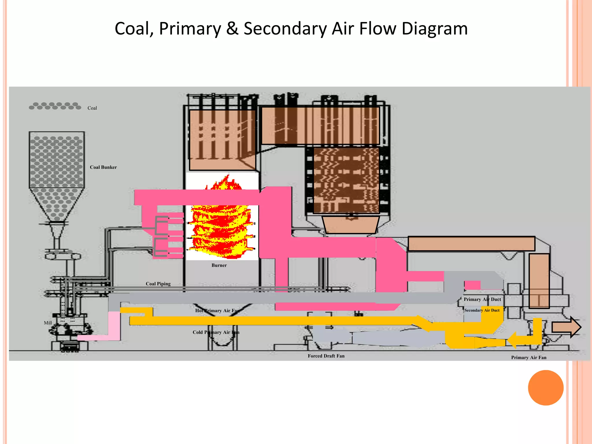
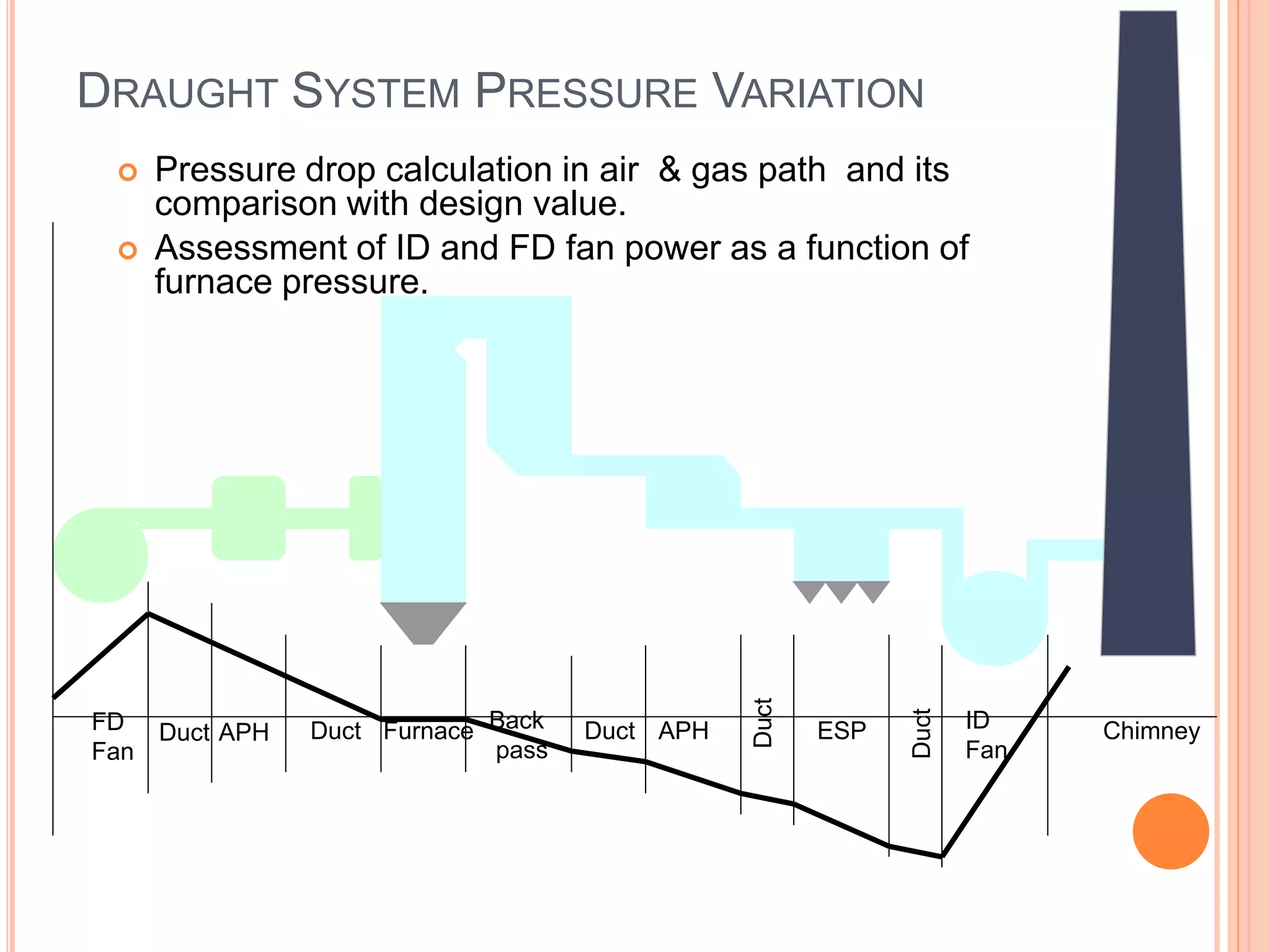
AIR AND GAS SYSTEM
INTRODUCTION
BoilerCombustion Air
Flue Gases
• Air needed for combustion
• Flue are needed to be evacuated
• Losses due to flow need to be overcome
Fuel
…
…
…
…
…
…
…
…
…
…
…
…
Coal
Coal Bunker
Mill
Forced Draft Fan
Primary Air Duct
Secondary Air Duct
Primary Air Fan
Cold Primary Air Fan
Hot Primary Air Fan
Coal Piping
Burner
Coal, Primary & Secondary Air Flow Diagram
FD
Fan
Duct APH Duct Furnace Duct APHBack
pass
ESP ID
Fan
Chimney
Duct
Duct
DRAUGHT SYSTEM PRESSURE VARIATION
 Pressure drop calculation in air & gas path and its
comparison with design value.
 Assessment of ID and FD fan power as a function of
furnace pressure.
MAJOR COMPONENTS
 Forced Draft Fan
 Induced Draft Fan
 Primary Air Fan
 Seal Air Fan
 Air Heater
 Steam Coil Air Pre heater
 Scanner Cooling Air Fan
 Ducting
 Damper
Impeller casing
Suction casing
Moving Blade
Regulating Mechanism
Bearing
Gas flow
28
MOVING BLADE1
ARM FOR MOVING BLADE SHAFT2
4
STOPPER PLATE FOR PACKING5
OPERATING PLATE6
PISTON7
ROTOR8
NUT FOR PISTON9
10 MOVING BLADE SHAFT
11 SLEEVE
12 V-PACKING (MV-TYPE)
13
COVER FOR MOVING BLADE
14
15 BUSH FOR MOVING BLADE ARM
16
17 PISTON RING
18
19 BOLT
20 BOLT
21 SET SCREW
23
24
SET SCREW
25
PARALLEL PIN
26
RETAINING RING
27
28 O-RING
29 BOLT
30 BALANCING WEIGHT
31 SET SCREW
32
CYLINDER COVER33
34
HUB DUST COVER35
36
SLIDING PIECE37
38 SLIDING PIECE (PIN TYPE)
39
40
41
45
SLEEVE
O-RING
O-RING
BOLT
BUSH FOR ARM WITH PIN
NUT FOR MOVING BLADE SHAFT RETAINING RING
WASHER
HYDRAULIC CYLINDER
BUSH FOR MOVING BLADE SHAFT
SUPPORT BEARING
LINKAGE MECHANISM
42 O RING
43 O-RING
74 BUSH
75 SET SCREW
77 SET SCREW
25
16
38
22 U-NUT
Rotor Shaft
Moving Blade
Coupling
Inner casing
Overall fan construction and flowpath
Diffuser
Rear casing
Construction Rotor and Moving Blade
Air heater leakage
Soot Blowers in RAPH
Fire detection probe
Provision is there to detect AH fire by detecting the abnormal temperature
increase inside RAPH
Thermocouples are installed at the Secondary Air side for detecting the
abnormal temperature rise and alarm accordingly
Water Washing Facility
Air heater elements can be water washed during a overhaul by water
washing system
Water used: Service Water
Water Pressure: 5.20 kpa g
Quantity/ hr (approx): 318 m3/hr
Air heater Assembly
Seal Air Fan
Type Centrifugal
Make TLT India Limited
Number 2X100%
Capacity 1000 m3/min
Motor rating 132KW/4 pole
Suction source Cold PA duct
Head developed 5500mm(Static)
Lubrication type Grease
Sealing air is required to seal the mill gearbox internals from PF dust. It is used in the following
location:-
Roller Journal
Grinding Table
Rotary Separator
GA of seal air fan
GA of seal air fan
Flame Scanner Cooling Air Fan
As the name suggests, flame scanner
cooling air fan required to supply the
cooling air to flame scanner.
There are 2X 100% flame scanner
cooling air fan, one AC and one DC
driven.
GA of scanner air fan
SCAPH Contd.
The purpose of SCAPH is to heat the secondary air during the initial firing condition
to prevent acid corrosion of air heater elements due to low flue gas temperature.
It is located at the discharge side of FD fan.
SCAPH overall dimension (mm) 8287X7392X1066
Tube material Carbon steel (SA 179 seamless)
Tube dimension (mm) 25.4ODX2.79 thk
Fins (mm) G type spiral fins (50.4 od X0.4 thk)
Fins material Carbon steel IS512/513
Header size 250NBX6525LGX9.3thk
Header Material SA106 gr. B
Ducts and dampers
Air and flue gas ducting system has the following major components
1. Ducting of rectangular, square or circular cross section with external
stiffeners and internal bracings
2. Expansion Joints ( Non-metallic / Fabric type or Metallic type )
3. Dampers
4. Guide vanes
5. Aerofoils
6. Access Doors
7. Duct Insulation
8. Duct supports ( Slings, Springs and Bearings)
9. Anchors/Guides ( Based on support philosophy )
A typical view of a duct section
Access Door
Aerofoil
Expansion joint
Support
• Classification
• Air Duct : Inlet air Duct carrying cold air to FD Fans and PA Fans,
Outlet duct from FD and PA fans to Air-preheater ( APH )
inlet.Tempering Air Duct from PA Discharge to Mill Inlet.Hot air
duct from Air-preheater ( APH ) to Boiler.
Generally it is made of 5mm thick carbon steel ( IS 2062
or ASTM A36 or equivalent )
• Flue/Gas Duct : Boiler Outlet duct from Economiser outlet to APH inlet ,
• APH Outlet to ESP inlet, ESP outlet to ID Fan inlet , ID
Fan outlet to Stack ( Chimney ) .
Generally it is made of 6 mm thick carbon steel ( IS
2062 or ASTM A36 or equivalent )
• DAMPERS:
• Functions : Main function of Dampers in Flues & Duct System is either to
control the flow of air /gas or to isolate the particular path of Flues & Duct
System for maintenance of equipments placed on that particular path.
• TYPE OF DAMPERS :
1. CONTROL DAMPERS :These dampers are of Louver type construction and
are used to control the flow of air /gas. For higher sealing SEAL AIR is
provided.
2. ON/OFF or ISOLATION DAMPERS: These dampers are also of Louver type
construction and are used to isolate the system with lesser sealing efficiency (
95%) , however SEAL AIR should be provided for better sealing.
3. GUILLOTINE DAMPERS : It is quick acting damper of Blade type
construction with sealing efficiency as 99.9%.This is provided at places where
complete isolation is required for maintenance purpose.
Thank You

Air & flue gas system

  • 1.
  • 2.
    INTRODUCTION BoilerCombustion Air Flue Gases •Air needed for combustion • Flue are needed to be evacuated • Losses due to flow need to be overcome Fuel
  • 3.
    … … … … … … … … … … … … Coal Coal Bunker Mill Forced DraftFan Primary Air Duct Secondary Air Duct Primary Air Fan Cold Primary Air Fan Hot Primary Air Fan Coal Piping Burner Coal, Primary & Secondary Air Flow Diagram
  • 4.
    FD Fan Duct APH DuctFurnace Duct APHBack pass ESP ID Fan Chimney Duct Duct DRAUGHT SYSTEM PRESSURE VARIATION  Pressure drop calculation in air & gas path and its comparison with design value.  Assessment of ID and FD fan power as a function of furnace pressure.
  • 5.
    MAJOR COMPONENTS  ForcedDraft Fan  Induced Draft Fan  Primary Air Fan  Seal Air Fan  Air Heater  Steam Coil Air Pre heater  Scanner Cooling Air Fan  Ducting  Damper
  • 6.
    Impeller casing Suction casing MovingBlade Regulating Mechanism Bearing Gas flow 28 MOVING BLADE1 ARM FOR MOVING BLADE SHAFT2 4 STOPPER PLATE FOR PACKING5 OPERATING PLATE6 PISTON7 ROTOR8 NUT FOR PISTON9 10 MOVING BLADE SHAFT 11 SLEEVE 12 V-PACKING (MV-TYPE) 13 COVER FOR MOVING BLADE 14 15 BUSH FOR MOVING BLADE ARM 16 17 PISTON RING 18 19 BOLT 20 BOLT 21 SET SCREW 23 24 SET SCREW 25 PARALLEL PIN 26 RETAINING RING 27 28 O-RING 29 BOLT 30 BALANCING WEIGHT 31 SET SCREW 32 CYLINDER COVER33 34 HUB DUST COVER35 36 SLIDING PIECE37 38 SLIDING PIECE (PIN TYPE) 39 40 41 45 SLEEVE O-RING O-RING BOLT BUSH FOR ARM WITH PIN NUT FOR MOVING BLADE SHAFT RETAINING RING WASHER HYDRAULIC CYLINDER BUSH FOR MOVING BLADE SHAFT SUPPORT BEARING LINKAGE MECHANISM 42 O RING 43 O-RING 74 BUSH 75 SET SCREW 77 SET SCREW 25 16 38 22 U-NUT 28 MOVING BLADE1 ARM FOR MOVING BLADE SHAFT2 4 STOPPER PLATE FOR PACKING5 OPERATING PLATE6 PISTON7 ROTOR8 NUT FOR PISTON9 10 MOVING BLADE SHAFT 11 SLEEVE 12 V-PACKING (MV-TYPE) 13 COVER FOR MOVING BLADE 14 15 BUSH FOR MOVING BLADE ARM 16 17 PISTON RING 18 19 BOLT 20 BOLT 21 SET SCREW 23 24 SET SCREW 25 PARALLEL PIN 26 RETAINING RING 27 28 O-RING 29 BOLT 30 BALANCING WEIGHT 31 SET SCREW 32 CYLINDER COVER33 34 HUB DUST COVER35 36 SLIDING PIECE37 38 SLIDING PIECE (PIN TYPE) 39 40 41 45 SLEEVE O-RING O-RING BOLT BUSH FOR ARM WITH PIN NUT FOR MOVING BLADE SHAFT RETAINING RING WASHER HYDRAULIC CYLINDER BUSH FOR MOVING BLADE SHAFT SUPPORT BEARING LINKAGE MECHANISM 42 O RING 43 O-RING 74 BUSH 75 SET SCREW 77 SET SCREW 25 16 38 22 U-NUT Rotor Shaft Moving Blade Coupling Inner casing Overall fan construction and flowpath Diffuser Rear casing
  • 8.
  • 13.
  • 14.
  • 15.
    Fire detection probe Provisionis there to detect AH fire by detecting the abnormal temperature increase inside RAPH Thermocouples are installed at the Secondary Air side for detecting the abnormal temperature rise and alarm accordingly Water Washing Facility Air heater elements can be water washed during a overhaul by water washing system Water used: Service Water Water Pressure: 5.20 kpa g Quantity/ hr (approx): 318 m3/hr
  • 16.
  • 17.
    Seal Air Fan TypeCentrifugal Make TLT India Limited Number 2X100% Capacity 1000 m3/min Motor rating 132KW/4 pole Suction source Cold PA duct Head developed 5500mm(Static) Lubrication type Grease Sealing air is required to seal the mill gearbox internals from PF dust. It is used in the following location:- Roller Journal Grinding Table Rotary Separator
  • 18.
    GA of sealair fan
  • 19.
    GA of sealair fan
  • 20.
    Flame Scanner CoolingAir Fan As the name suggests, flame scanner cooling air fan required to supply the cooling air to flame scanner. There are 2X 100% flame scanner cooling air fan, one AC and one DC driven.
  • 21.
  • 22.
  • 23.
    SCAPH Contd. The purposeof SCAPH is to heat the secondary air during the initial firing condition to prevent acid corrosion of air heater elements due to low flue gas temperature. It is located at the discharge side of FD fan. SCAPH overall dimension (mm) 8287X7392X1066 Tube material Carbon steel (SA 179 seamless) Tube dimension (mm) 25.4ODX2.79 thk Fins (mm) G type spiral fins (50.4 od X0.4 thk) Fins material Carbon steel IS512/513 Header size 250NBX6525LGX9.3thk Header Material SA106 gr. B
  • 24.
    Ducts and dampers Airand flue gas ducting system has the following major components 1. Ducting of rectangular, square or circular cross section with external stiffeners and internal bracings 2. Expansion Joints ( Non-metallic / Fabric type or Metallic type ) 3. Dampers 4. Guide vanes 5. Aerofoils 6. Access Doors 7. Duct Insulation 8. Duct supports ( Slings, Springs and Bearings) 9. Anchors/Guides ( Based on support philosophy )
  • 25.
    A typical viewof a duct section Access Door Aerofoil Expansion joint Support
  • 26.
    • Classification • AirDuct : Inlet air Duct carrying cold air to FD Fans and PA Fans, Outlet duct from FD and PA fans to Air-preheater ( APH ) inlet.Tempering Air Duct from PA Discharge to Mill Inlet.Hot air duct from Air-preheater ( APH ) to Boiler. Generally it is made of 5mm thick carbon steel ( IS 2062 or ASTM A36 or equivalent ) • Flue/Gas Duct : Boiler Outlet duct from Economiser outlet to APH inlet , • APH Outlet to ESP inlet, ESP outlet to ID Fan inlet , ID Fan outlet to Stack ( Chimney ) . Generally it is made of 6 mm thick carbon steel ( IS 2062 or ASTM A36 or equivalent )
  • 27.
    • DAMPERS: • Functions: Main function of Dampers in Flues & Duct System is either to control the flow of air /gas or to isolate the particular path of Flues & Duct System for maintenance of equipments placed on that particular path. • TYPE OF DAMPERS : 1. CONTROL DAMPERS :These dampers are of Louver type construction and are used to control the flow of air /gas. For higher sealing SEAL AIR is provided. 2. ON/OFF or ISOLATION DAMPERS: These dampers are also of Louver type construction and are used to isolate the system with lesser sealing efficiency ( 95%) , however SEAL AIR should be provided for better sealing. 3. GUILLOTINE DAMPERS : It is quick acting damper of Blade type construction with sealing efficiency as 99.9%.This is provided at places where complete isolation is required for maintenance purpose.
  • 28.