Downloaded 856 times
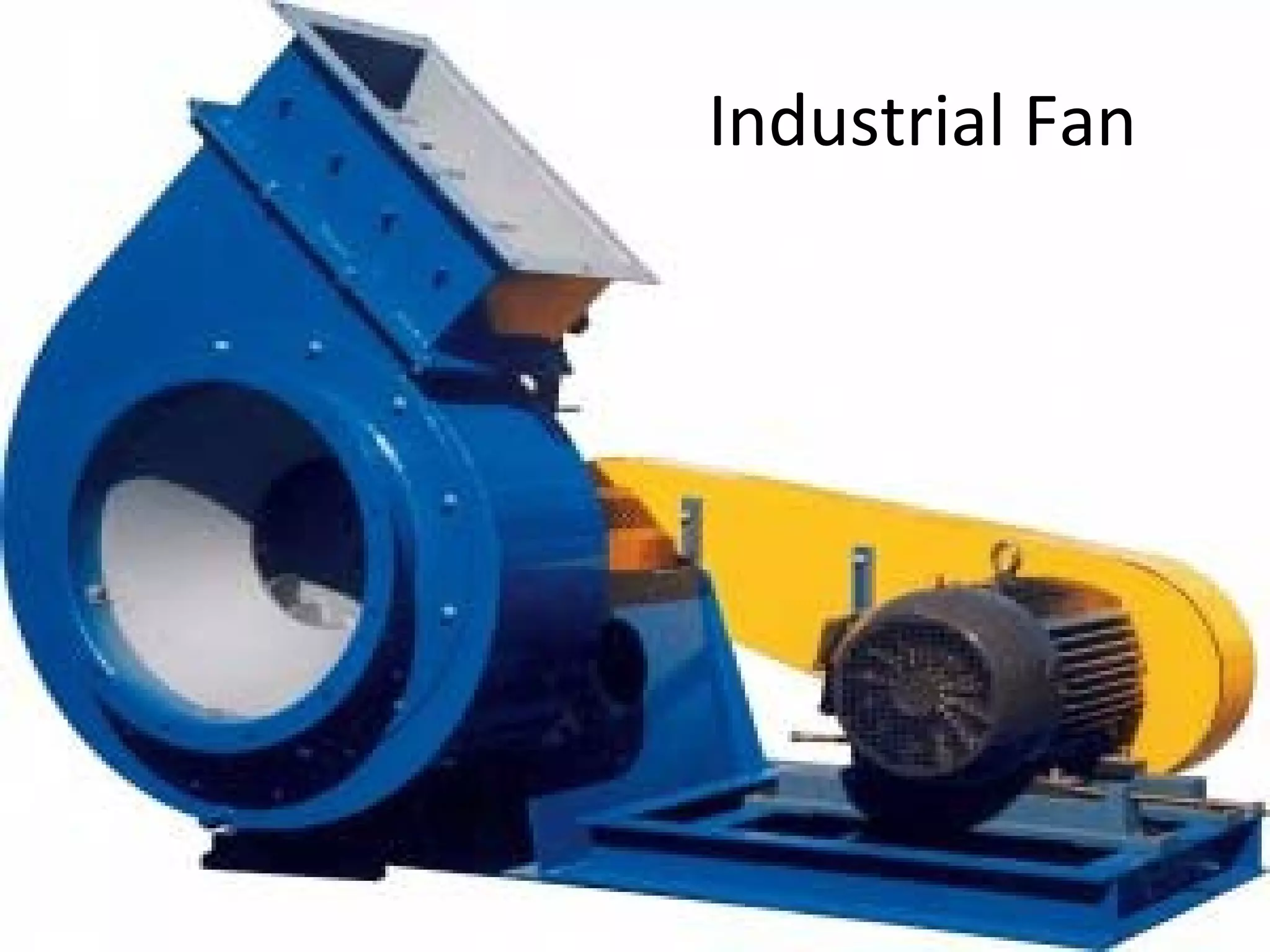


1. The document discusses industrial fans and draft systems for combustion. It describes natural draft produced by chimneys and mechanical draft produced using fans. 2. The main types of mechanical draft systems are induced draft, forced draft, and balanced draft. Induced draft uses a fan to draw exhaust gases into the chimney. Forced draft uses a fan to push air into the furnace. 3. The document provides details on fan construction, types of fans including axial and centrifugal, installation procedures, and maintenance best practices like lubrication and vibration checking.


