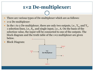
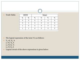
P R O F . N E E R A J B H A R G A V A
M R S . P O O J A D I X I T
D E P A R T M E N T O F C O M P U T E R S C I E N C E ,
S C H O O L O F E N G I N E E R I N G & S Y S T E M
S C I E N C E S
M D S U N I V E R S I T Y A J M E R , R A J A S T H A N
De-multiplexer
Introduction
 A De-multiplexer is a combinational circuit that has only
1 input line and 2N output lines. Simply, the multiplexer
is a single-input and multi-output combinational circuit.
The information is received from the single input lines
and directed to the output line. On the basis of the values
of the selection lines, the input will be connected to one
of these outputs. De-multiplexer is opposite to the
multiplexer.
 Unlike encoder and decoder, there are n selection lines
and 2n outputs. So, there is a total of 2n possible
combinations of inputs. De-multiplexer is also treated
as De-mux.
1×2 De-multiplexer:
 There are various types of De-multiplexer which are as follows:
 1×2 De-multiplexer:
 In the 1 to 2 De-multiplexer, there are only two outputs, i.e., Y0, and Y1,
1 selection lines, i.e., S0, and single input, i.e., A. On the basis of the
selection value, the input will be connected to one of the outputs. The
block diagram and the truth table of the 1×2 multiplexer are given
below.
 Block Diagram:
 Truth Table:
 The logical expression of the term
Y is as follows:
 Y0=S0'.A
Y1=S0.A
 Logical circuit of the above
expressions is given below:
1×4 De-multiplexer:
 In 1 to 4 De-multiplexer, there are total of four outputs, i.e., Y0, Y1, Y2, and Y3, 2
selection lines, i.e., S0 and S1 and single input, i.e., A. On the basis of the
combination of inputs which are present at the selection lines S0 and S1, the
input be connected to one of the outputs. The block diagram and the truth table
of the 1×4 multiplexer are given below.
 Block Diagram:

 Truth Table:
 The logical expression of the term Y is as follows:
 Y0=S1' S0' A
y1=S1' S0 A
y2=S1 S0' A
y3=S1 S0 A
 Logical circuit of the above expressions is given below:
De-multiplexer.pptx

De-multiplexer.pptx

  • 1.
    P R OF . N E E R A J B H A R G A V A M R S . P O O J A D I X I T D E P A R T M E N T O F C O M P U T E R S C I E N C E , S C H O O L O F E N G I N E E R I N G & S Y S T E M S C I E N C E S M D S U N I V E R S I T Y A J M E R , R A J A S T H A N De-multiplexer
  • 2.
    Introduction  A De-multiplexeris a combinational circuit that has only 1 input line and 2N output lines. Simply, the multiplexer is a single-input and multi-output combinational circuit. The information is received from the single input lines and directed to the output line. On the basis of the values of the selection lines, the input will be connected to one of these outputs. De-multiplexer is opposite to the multiplexer.  Unlike encoder and decoder, there are n selection lines and 2n outputs. So, there is a total of 2n possible combinations of inputs. De-multiplexer is also treated as De-mux.
  • 3.
    1×2 De-multiplexer:  Thereare various types of De-multiplexer which are as follows:  1×2 De-multiplexer:  In the 1 to 2 De-multiplexer, there are only two outputs, i.e., Y0, and Y1, 1 selection lines, i.e., S0, and single input, i.e., A. On the basis of the selection value, the input will be connected to one of the outputs. The block diagram and the truth table of the 1×2 multiplexer are given below.  Block Diagram:
  • 4.
     Truth Table: The logical expression of the term Y is as follows:  Y0=S0'.A Y1=S0.A  Logical circuit of the above expressions is given below:
  • 5.
    1×4 De-multiplexer:  In1 to 4 De-multiplexer, there are total of four outputs, i.e., Y0, Y1, Y2, and Y3, 2 selection lines, i.e., S0 and S1 and single input, i.e., A. On the basis of the combination of inputs which are present at the selection lines S0 and S1, the input be connected to one of the outputs. The block diagram and the truth table of the 1×4 multiplexer are given below.  Block Diagram: 
  • 6.
     Truth Table: The logical expression of the term Y is as follows:  Y0=S1' S0' A y1=S1' S0 A y2=S1 S0' A y3=S1 S0 A  Logical circuit of the above expressions is given below: