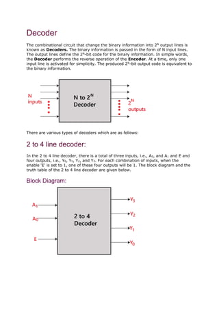
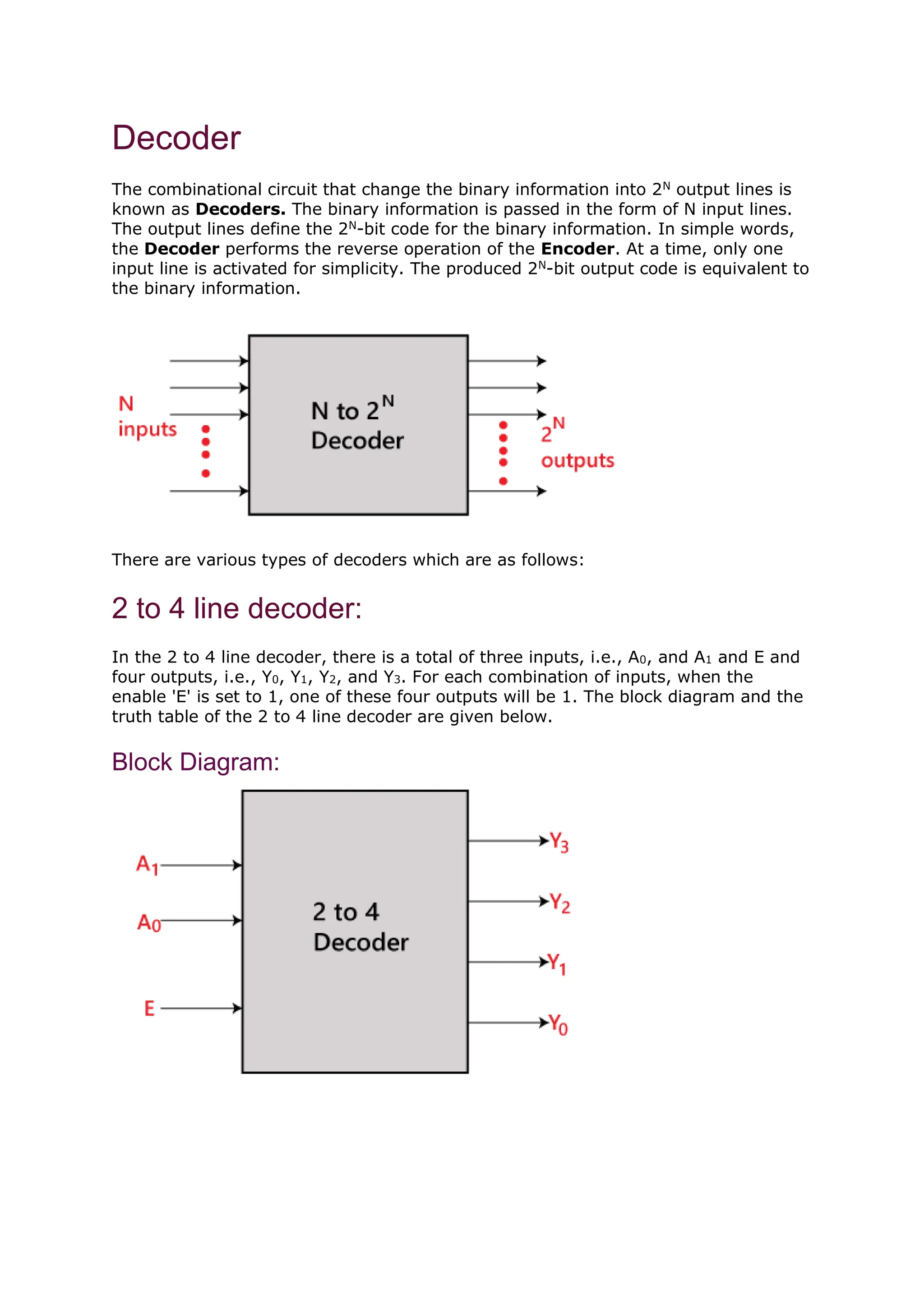
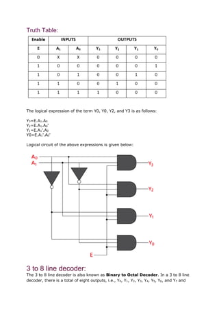
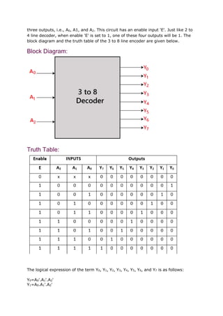
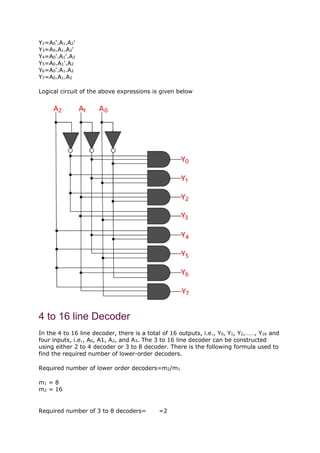
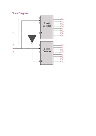
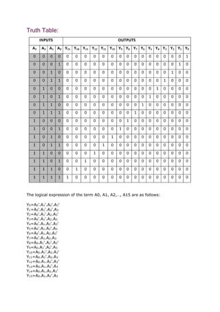
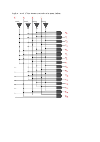
Decoder
The combinational circuit that change the binary information into 2N
output lines is
known as Decoders. The binary information is passed in the form of N input lines.
The output lines define the 2N
-bit code for the binary information. In simple words,
the Decoder performs the reverse operation of the Encoder. At a time, only one
input line is activated for simplicity. The produced 2N
-bit output code is equivalent to
the binary information.
There are various types of decoders which are as follows:
2 to 4 line decoder:
In the 2 to 4 line decoder, there is a total of three inputs, i.e., A0, and A1 and E and
four outputs, i.e., Y0, Y1, Y2, and Y3. For each combination of inputs, when the
enable 'E' is set to 1, one of these four outputs will be 1. The block diagram and the
truth table of the 2 to 4 line decoder are given below.
Block Diagram:
Truth Table:
The logical expression of the term Y0, Y0, Y2, and Y3 is as follows:
Y3=E.A1.A0
Y2=E.A1.A0'
Y1=E.A1'.A0
Y0=E.A1'.A0'
Logical circuit of the above expressions is given below:
3 to 8 line decoder:
The 3 to 8 line decoder is also known as Binary to Octal Decoder. In a 3 to 8 line
decoder, there is a total of eight outputs, i.e., Y0, Y1, Y2, Y3, Y4, Y5, Y6, and Y7 and
three outputs, i.e., A0, A1, and A2. This circuit has an enable input 'E'. Just like 2 to
4 line decoder, when enable 'E' is set to 1, one of these four outputs will be 1. The
block diagram and the truth table of the 3 to 8 line encoder are given below.
Block Diagram:
Truth Table:
The logical expression of the term Y0, Y1, Y2, Y3, Y4, Y5, Y6, and Y7 is as follows:
Y0=A0'.A1'.A2'
Y1=A0.A1'.A2'
Y2=A0'.A1.A2'
Y3=A0.A1.A2'
Y4=A0'.A1'.A2
Y5=A0.A1'.A2
Y6=A0'.A1.A2
Y7=A0.A1.A2
Logical circuit of the above expressions is given below
4 to 16 line Decoder
In the 4 to 16 line decoder, there is a total of 16 outputs, i.e., Y0, Y1, Y2,……, Y16 and
four inputs, i.e., A0, A1, A2, and A3. The 3 to 16 line decoder can be constructed
using either 2 to 4 decoder or 3 to 8 decoder. There is the following formula used to
find the required number of lower-order decoders.
Required number of lower order decoders=m2/m1
m1 = 8
m2 = 16
Required number of 3 to 8 decoders= =2
Block Diagram:
Truth Table:
The logical expression of the term A0, A1, A2,…, A15 are as follows:
Y0=A0'.A1'.A2'.A3'
Y1=A0'.A1'.A2'.A3
Y2=A0'.A1'.A2.A3'
Y3=A0'.A1'.A2.A3
Y4=A0'.A1.A2'.A3'
Y5=A0'.A1.A2'.A3
Y6=A0'.A1.A2.A3'
Y7=A0'.A1.A2.A3
Y8=A0.A1'.A2'.A3'
Y9=A0.A1'.A2'.A3
Y10=A0.A1'.A2.A3'
Y11=A0.A1'.A2.A3
Y12=A0.A1.A2'.A3'
Y13=A0.A1.A2'.A3
Y14=A0.A1.A2.A3'
Y15=A0.A1.A2'.A3
Logical circuit of the above expressions is given below:

Computer Architecture_Decoder NOTES.docx

  • 1.
    Decoder The combinational circuitthat change the binary information into 2N output lines is known as Decoders. The binary information is passed in the form of N input lines. The output lines define the 2N -bit code for the binary information. In simple words, the Decoder performs the reverse operation of the Encoder. At a time, only one input line is activated for simplicity. The produced 2N -bit output code is equivalent to the binary information. There are various types of decoders which are as follows: 2 to 4 line decoder: In the 2 to 4 line decoder, there is a total of three inputs, i.e., A0, and A1 and E and four outputs, i.e., Y0, Y1, Y2, and Y3. For each combination of inputs, when the enable 'E' is set to 1, one of these four outputs will be 1. The block diagram and the truth table of the 2 to 4 line decoder are given below. Block Diagram:
  • 2.
    Truth Table: The logicalexpression of the term Y0, Y0, Y2, and Y3 is as follows: Y3=E.A1.A0 Y2=E.A1.A0' Y1=E.A1'.A0 Y0=E.A1'.A0' Logical circuit of the above expressions is given below: 3 to 8 line decoder: The 3 to 8 line decoder is also known as Binary to Octal Decoder. In a 3 to 8 line decoder, there is a total of eight outputs, i.e., Y0, Y1, Y2, Y3, Y4, Y5, Y6, and Y7 and
  • 3.
    three outputs, i.e.,A0, A1, and A2. This circuit has an enable input 'E'. Just like 2 to 4 line decoder, when enable 'E' is set to 1, one of these four outputs will be 1. The block diagram and the truth table of the 3 to 8 line encoder are given below. Block Diagram: Truth Table: The logical expression of the term Y0, Y1, Y2, Y3, Y4, Y5, Y6, and Y7 is as follows: Y0=A0'.A1'.A2' Y1=A0.A1'.A2'
  • 4.
    Y2=A0'.A1.A2' Y3=A0.A1.A2' Y4=A0'.A1'.A2 Y5=A0.A1'.A2 Y6=A0'.A1.A2 Y7=A0.A1.A2 Logical circuit ofthe above expressions is given below 4 to 16 line Decoder In the 4 to 16 line decoder, there is a total of 16 outputs, i.e., Y0, Y1, Y2,……, Y16 and four inputs, i.e., A0, A1, A2, and A3. The 3 to 16 line decoder can be constructed using either 2 to 4 decoder or 3 to 8 decoder. There is the following formula used to find the required number of lower-order decoders. Required number of lower order decoders=m2/m1 m1 = 8 m2 = 16 Required number of 3 to 8 decoders= =2
  • 5.
  • 6.
    Truth Table: The logicalexpression of the term A0, A1, A2,…, A15 are as follows: Y0=A0'.A1'.A2'.A3' Y1=A0'.A1'.A2'.A3 Y2=A0'.A1'.A2.A3' Y3=A0'.A1'.A2.A3 Y4=A0'.A1.A2'.A3' Y5=A0'.A1.A2'.A3 Y6=A0'.A1.A2.A3' Y7=A0'.A1.A2.A3 Y8=A0.A1'.A2'.A3' Y9=A0.A1'.A2'.A3 Y10=A0.A1'.A2.A3' Y11=A0.A1'.A2.A3 Y12=A0.A1.A2'.A3' Y13=A0.A1.A2'.A3 Y14=A0.A1.A2.A3' Y15=A0.A1.A2'.A3
  • 7.
    Logical circuit ofthe above expressions is given below: