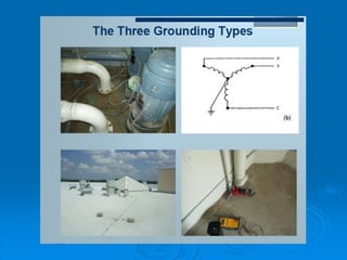
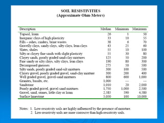
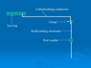
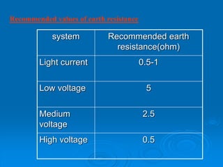
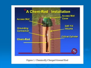
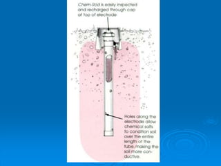
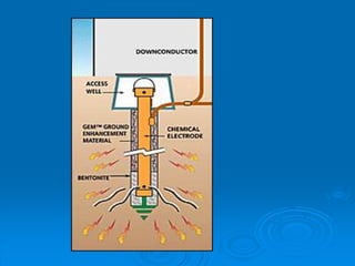
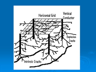
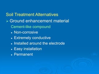
The document discusses grounding systems and their objectives which are to provide safety, ensure correct operation of equipment, prevent damage, dissipate lightning, stabilize voltage, and divert stray RF energy. It describes the three main types of grounding as equipment, system, and lightning/surge grounding. Various grounding components and methods are defined including earth electrodes, earthing conductors, earthing grids, soil characteristics, recommended earth resistance values, and substation earthing systems. New methods to decrease ground resistance such as chemical rods, grounding augmentation fill, and cracks filled with low resistivity materials are also summarized.
What is Grounding?
• Importance of Grounding
• Types of Grounding
• Applications of Grounding in power system
• Instruments employed in Grounding
• Grounding procedure & calculations
• Hazards due to lack of Grounding
• Good Grounding practice
• IEEE rules regarding Grounding
• Conclusion
What is Grounding?
• Importance of Grounding
• Types of Grounding
• Applications of Grounding in power system
• Instruments employed in Grounding
• Grounding procedure & calculations
• Hazards due to lack of Grounding
• Good Grounding practice
• IEEE rules regarding Grounding
• Conclusion
Electrical fault is the deviation of voltages and currents from nominal values or states. Under normal operating conditions, power system equipment or lines carry normal voltages and currents which results in a safer operation of the system.
Grounding or earthing offers two principal advantages. First, it provides protection to the power system. Secondly, earthing of electrical equipment ensures the safety of the persons handling the equipment.
A switchgear or electrical switchgear is a generic term which includes all the switching devices associated with mainly power system protection. It also includes all devices associated with control, metering and regulating of electrical power system. Assembly of such devices in a logical manner forms a switchgear. This is the very basic definition of switchgear.
⋗To get more with details
https://www.youtube.com/channel/UC2SvKI7eepP241VLoui1D5A
PPT on earthing, grounding and isolation made by the students of SVIT,Vasad under the valuable guidance of the faculties teaching us Electronics and Electrical workshop(EEW) under the course of GTU.
SYSTEM NEUTRAL EARTHING
-DEFINITION OF SYSTEM EARTHING
-Comparative Performance For Various Conditions Using Different Earthing Methods
-EQUIPMENT SIZING
- APPENDIX FOR TYPICAL EARTHING TRANSFORMER SIZING
- APPENDIX GIVING GUIDELINE FOR SIZING OF COMMON BUS CONNECTED MEDIUM RESISTANCE EARTHING
Successful operation of entire power system depends to a considerable extent on efficient and satisfactory performance of substations. Hence substations in general can be considered as heart of overall power system. In any substation, a well-designed grounding plays an important role. Since absence of safe and effective grounding system can result in mal-operation or non-operation of control and protective devices, grounding system design deserves considerable attention for all the substations. There are two primary functions of a safe earthing system. Firstly, ensure that a person who is in the vicinity of earthed facilities during a fault is not exposed to the possibility of a fatal electrical shock. Secondly, provide a low impedance path to earth for currents occurring under normal and fault conditions.The earthing conductors, composing the grid and connections to all equipment and structures, must possess sufficient thermal capacity to pass the highest fault current for the required time
Hybrid optimization of pumped hydro system and solar- Engr. Abdul-Azeez.pdffxintegritypublishin
Advancements in technology unveil a myriad of electrical and electronic breakthroughs geared towards efficiently harnessing limited resources to meet human energy demands. The optimization of hybrid solar PV panels and pumped hydro energy supply systems plays a pivotal role in utilizing natural resources effectively. This initiative not only benefits humanity but also fosters environmental sustainability. The study investigated the design optimization of these hybrid systems, focusing on understanding solar radiation patterns, identifying geographical influences on solar radiation, formulating a mathematical model for system optimization, and determining the optimal configuration of PV panels and pumped hydro storage. Through a comparative analysis approach and eight weeks of data collection, the study addressed key research questions related to solar radiation patterns and optimal system design. The findings highlighted regions with heightened solar radiation levels, showcasing substantial potential for power generation and emphasizing the system's efficiency. Optimizing system design significantly boosted power generation, promoted renewable energy utilization, and enhanced energy storage capacity. The study underscored the benefits of optimizing hybrid solar PV panels and pumped hydro energy supply systems for sustainable energy usage. Optimizing the design of solar PV panels and pumped hydro energy supply systems as examined across diverse climatic conditions in a developing country, not only enhances power generation but also improves the integration of renewable energy sources and boosts energy storage capacities, particularly beneficial for less economically prosperous regions. Additionally, the study provides valuable insights for advancing energy research in economically viable areas. Recommendations included conducting site-specific assessments, utilizing advanced modeling tools, implementing regular maintenance protocols, and enhancing communication among system components.
Saudi Arabia stands as a titan in the global energy landscape, renowned for its abundant oil and gas resources. It's the largest exporter of petroleum and holds some of the world's most significant reserves. Let's delve into the top 10 oil and gas projects shaping Saudi Arabia's energy future in 2024.
Immunizing Image Classifiers Against Localized Adversary Attacksgerogepatton
This paper addresses the vulnerability of deep learning models, particularly convolutional neural networks
(CNN)s, to adversarial attacks and presents a proactive training technique designed to counter them. We
introduce a novel volumization algorithm, which transforms 2D images into 3D volumetric representations.
When combined with 3D convolution and deep curriculum learning optimization (CLO), itsignificantly improves
the immunity of models against localized universal attacks by up to 40%. We evaluate our proposed approach
using contemporary CNN architectures and the modified Canadian Institute for Advanced Research (CIFAR-10
and CIFAR-100) and ImageNet Large Scale Visual Recognition Challenge (ILSVRC12) datasets, showcasing
accuracy improvements over previous techniques. The results indicate that the combination of the volumetric
input and curriculum learning holds significant promise for mitigating adversarial attacks without necessitating
adversary training.
Sachpazis:Terzaghi Bearing Capacity Estimation in simple terms with Calculati...Dr.Costas Sachpazis
Terzaghi's soil bearing capacity theory, developed by Karl Terzaghi, is a fundamental principle in geotechnical engineering used to determine the bearing capacity of shallow foundations. This theory provides a method to calculate the ultimate bearing capacity of soil, which is the maximum load per unit area that the soil can support without undergoing shear failure. The Calculation HTML Code included.
Hierarchical Digital Twin of a Naval Power SystemKerry Sado
A hierarchical digital twin of a Naval DC power system has been developed and experimentally verified. Similar to other state-of-the-art digital twins, this technology creates a digital replica of the physical system executed in real-time or faster, which can modify hardware controls. However, its advantage stems from distributing computational efforts by utilizing a hierarchical structure composed of lower-level digital twin blocks and a higher-level system digital twin. Each digital twin block is associated with a physical subsystem of the hardware and communicates with a singular system digital twin, which creates a system-level response. By extracting information from each level of the hierarchy, power system controls of the hardware were reconfigured autonomously. This hierarchical digital twin development offers several advantages over other digital twins, particularly in the field of naval power systems. The hierarchical structure allows for greater computational efficiency and scalability while the ability to autonomously reconfigure hardware controls offers increased flexibility and responsiveness. The hierarchical decomposition and models utilized were well aligned with the physical twin, as indicated by the maximum deviations between the developed digital twin hierarchy and the hardware.
2. The objective of a grounding system are:
1. To provide safety to personnel during normal and fault
conditions by limiting step and touch potential.
2. To assure correct operation of electrical/electronic
devices.
3. To prevent damage to electrical/electronic apparatus.
4. To dissipate lightning strokes.
5. To stabilize voltage during transient conditions and to
minimize the probability of flashover during transients.
6. To divert stray RF energy from sensitive audio, video,
control, and computer equipment.
3. A safe grounding design has two objectives:
1. To provide means to carry electric currents
into the earth under normal and fault
conditions without exceeding any operating
and equipment limits or adversely affecting
continuity of service.
2. To assure that a person in the vicinity of
grounded facilities is not exposed to the
danger of critical electric shock.
4. The PRIMARY goal of the grounding
system throughout any facilities is
SAFETY.
Why ground at all?
PERSONNEL SAFETY FIRST
EQUIPMENT PROTECTION SECOND
5. The three main types are:
EQUIPMENT GROUNDING (SAFETY)
SYSTEM GROUNDING
LIGHTNING/SURGE GROUNDING
What are the three main types
of grounding?
6.
7. Soil Characteristics
Soil type. Soil resistivity varies widely
depending on soil type, from as low as 1
Ohmmeter for moist loamy topsoil to almost
10,000 Ohm-meters for surface limestone.
Moisture content is one of the controlling
factors in earth resistance because electrical
conduction in soil is essentially electrolytic.
14. Factors involved in effective earthing
•Effect of shape on electrode resistance
•Soil resistivity
•Plate
•Rod
•Horizontal strip or round conductor electrodes
15. Recommended values of earth resistance
Recommended earth
resistance(ohm)
system
0.5-1
Light current
5
Low voltage
2.5
Medium
voltage
0.5
High voltage
19. Step potential
“Step potential” is the voltage
between the feet of a person standing
near an energized grounded object.
It is equal to the difference in voltage,
given by the voltage distribution curve,
between two points at different
distances from the “electrode.”
A person could be at risk of injury
during a fault simply by standing near
the grounding point.
20. Touch potential
“Touch potential” is the voltage between
the energized object and the feet of a
person in contact with the object.
It is equal to the difference in voltage
between the energized object and a point
some distance away.
The touch potential could be nearly the
full voltage across the grounded object if
that object is grounded at a point remote
from the place where the person is in
contact with it.
22. Resistance of driven rods:
The Ground Resistance (R) of a single rod, of diameter (d) an
driven length (i) driven vertically into the soil of resistivity (ρ), can
be calculated as follows:
where: ρ Soil Resistivity in m
l Buried Length of the electrode in m
d Diameter of the electrode in m
The rod is assumed as carrying current uniformly along its rod.
Examples
(a) 20mm rod of 3m length and Soil resistivity 50 Ω-m .....R=16.1 Ω
(b) 25mm rod of 2m length and Soil resistivity 30 Ω-m .....R=13.0 Ω
1
8
ln
2 d
l
l
R
24. The resistance of a single rod is not sufficiently
low.
A number of rods are connected in parallel.
They should be driven far apart as possible to
minimize the overlap among their areas of
influence.
It is necessary to determine the net reduction in
the total resistance by connecting rods in
parallel.
The rod is replaced by a hemispherical
electrode having the same resistance.
25. Rod Electrodes in Parallel
If the desired ground resistance cannot be
achieved with one ground electrode, the overall
resistance can be reduced by connecting a
number of electrodes in parallel.
These are called “arrays of rod electrodes”.
The combined resistance is a function of the
number and configuration of electrodes, the
separation between them, their dimensions and
soil resistivity.
Rods in parallel should be spaced at least twice
their length to utilize the full benefit of the
additional rods.
26. If the separation of the electrodes is much
larger than their lengths and only a few
electrodes are in parallel, then the resultant
ground resistance can be calculated using the
ordinary equation for resistances in parallel.
In practice, the effective ground resistance will
usually be higher than this.
Typically, a 4 spike array may provide an
improvement of about 2.5 to 3 times.
An 8 spike array will typically give an
improvement of may be 5 to 6 times.
27. The multiple driven rod electrode
The driven rod is an economical and simple means
of making an earth connection but its resistance is
not sufficiently low.
A number of rods are connected in parallel.
They should be driven far apart as possible to
minimize the overlap among their areas of
influence.
It is necessary to determine the net reduction in the
total resistance by connecting rods in parallel.
The rod is replaced by a hemispherical electrode
having the same resistance.
28. The method consists of assuming that
each equivalent hemisphere carries the
same charge.
Calculate the average potential of the
group of rods.
From this and the total charge the capacity
and the resistance can be calculated.
34. METHODS OF DECREASING GROUND
RESISTANCE
Decreasing the ground resistance of a
grounding system in high resistivity soil is
often a formidable task.
Recently, some new methods have been
proposed to decrease ground resistance.
35. 1-Chemical Rods
Chemical rods are electrodes with holes along
their length, filled with mineral salts.
The specially formulated mineral salts are
evenly distributed along the entire length of the
electrode.
The rod absorbs moisture from both air and soil.
Continuous conditioning of a large area insures
an ultra-low-resistance ground which is more
effective than a conventional electrode.
36. If the conductive salts are running low, the
rod can be recharged with a refill kit.
These rods are available in vertical and
horizontal configurations.
They may be used in rocky soils, freezing
climates, dry deserts, or tropical rain
forests.
They provide stable protection for many
years.
37.
38.
39.
40.
41.
42.
43. Disadvantages are:
Chemicals concentrated around
electrodes will cause corrosion
Chemicals leach through the soil and
dissipate
Scheduled replacement may be required
May be prohibited because they may
contaminate the water table
44. 2- Grounding Augmentation Fill (GAF)
About 95% of the grounding resistance of a
given electrode is determined by the character
of the soil within a hemisphere whose radius is
1.1 times the length of the rod.
It is obvious that replacing all or part of that soil
with a highly conductive backfill will facilitate the
achievement of a low-resistance ground
connection.
The greater the percentage of soil replaced, the
lower the ultimate grounding resistance.
46. The amount of the backfill material required is
determined in most cases by the Interfacing
Volume and Critical Cylinder principles.
A ground electrode establishes a connection to
earth by affecting only a certain volume of
earth, called the Interfacing Volume (IV).
For practical purposes for a ground rod the
entire connection to earth is contained within
an IV whose radius is 2.5 times the length of
the rod.
47. Most of the earth connection takes place in a
cylinder close to the electrode, called the
Critical Cylinder.
A study of the influence of soil within the IV
demonstrates that six inches of soil along any
radial makes up 52 per cent of the connection
to earth; a 12 inches makes up 68 percent of
the connection.
48. Beyond a diameter of 24 inches there is
very little improvement for much larger
diameters.
Therefore, the recommended diameter for
the Critical Cylinder is between 12 and 24
inches, and the calculated amount of the
required backfill material is based on that
diameter and the length of the ground rod.
49. 3- Cracks with Low Resistivity Materials
(LRM)
This method requires 3 steps:
Drilling deep holes in the ground, developing
cracks in the soil by means of explosions in
the holes, filling the holes with low resistivity
materials (LRM) under pressure.
Most of the cracks around the vertical
conductors will be filled with LRM, and a
complex network of low resistivity tree like
cracks linked to the substation grid is formed.
50. Field tests show that the optimum span
between vertical conductors is in the range
of 1.5-2 times the length of the vertical
conductor.
This method is effective in reducing
ground resistances in rocky areas.
51.
52. Soil Treatment Alternatives
Ground enhancement material
Cement-like compound
Non-corrosive
Extremely conductive
Installed around the electrode
Easy installation
Permanent
53. Conductive Cement
Concrete has a resistivity range of 30 to 90 Ohm-
meters.
Since it is hygroscopic by nature it will tend to absorb
moisture when available and keep it up to 30 days,
thus maintaining a resistivity lower than the
surrounding soil.
However, during a long dry season concrete will dry
out with a subsequent rise in resistivity.
Also, if a substantial amount of fault or lightning
current is injected into a concrete encased electrode,
the moisture in the concrete may become steam,
dramatically increasing in volume and placing a
substantial stress on the concrete.
54. Installing an EARTHLINK 101 earthling strip is
simple:
Dig a trench and lay in the wire.
55. Pour EARTHLINK 101 conductive cement, using the handy
applicator bag, and shovel in a thin protective layer of soil.