Grounding in Power System Presentation
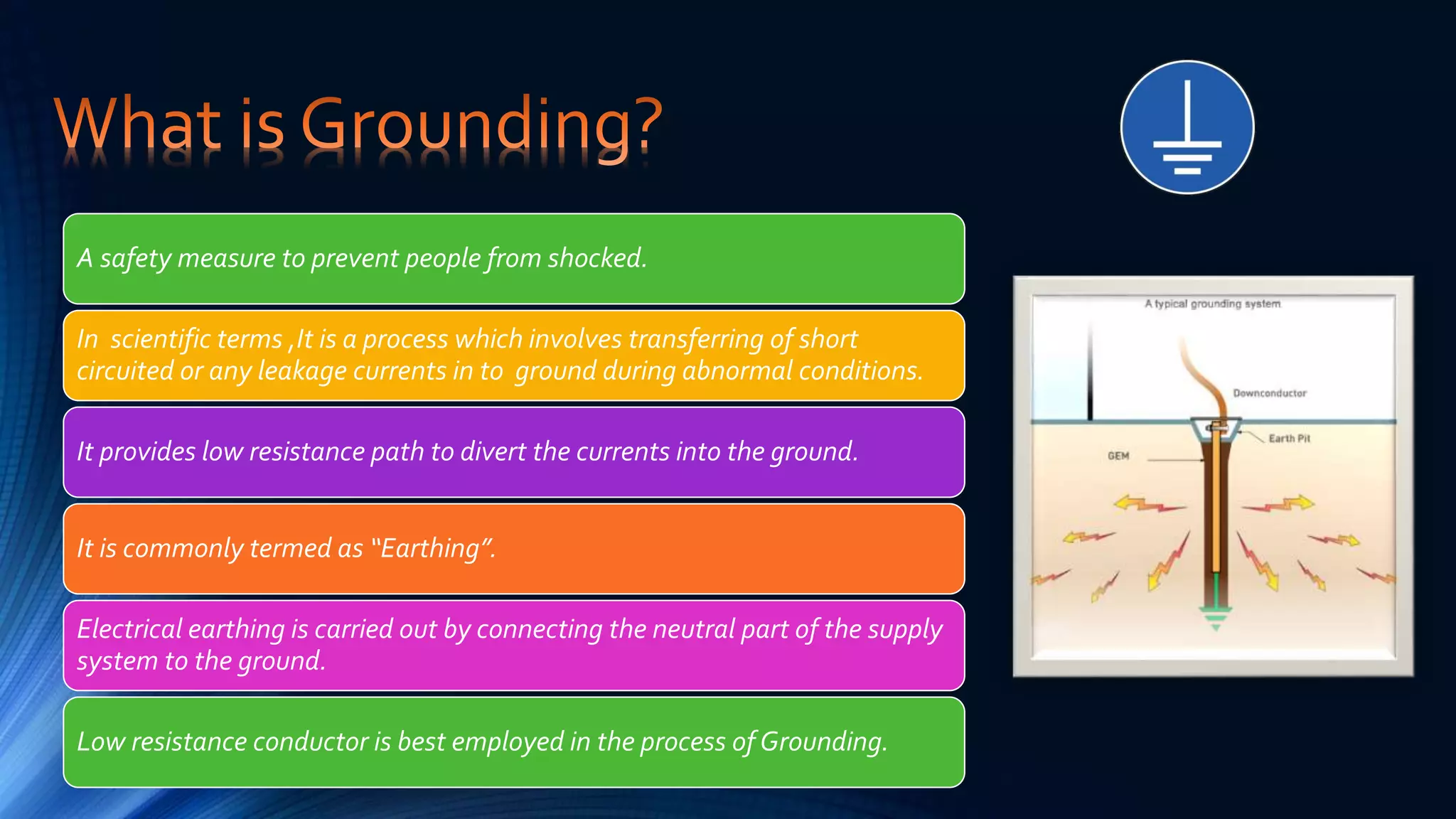
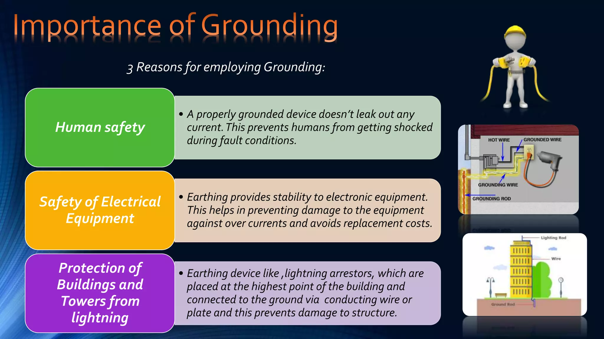
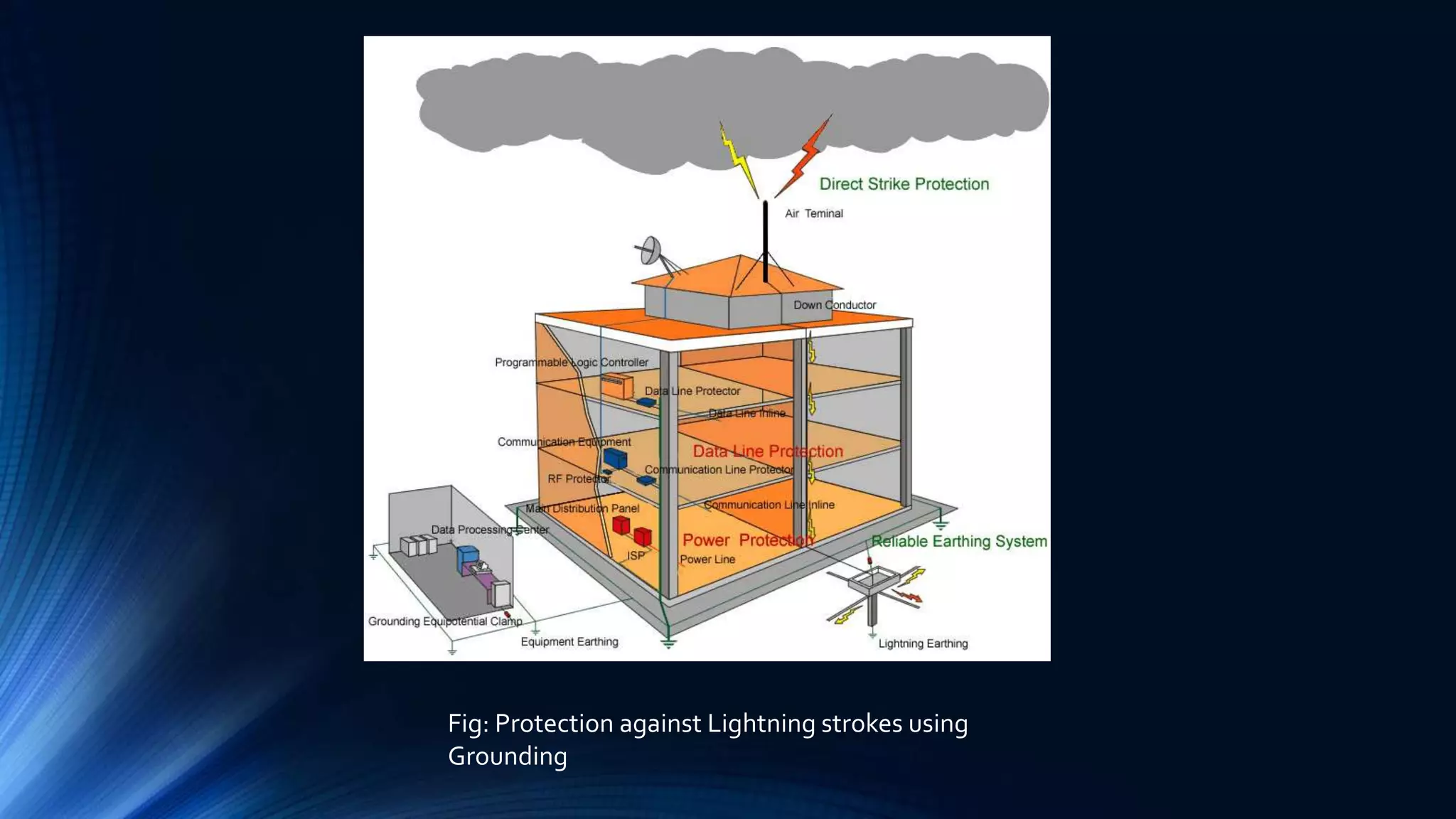
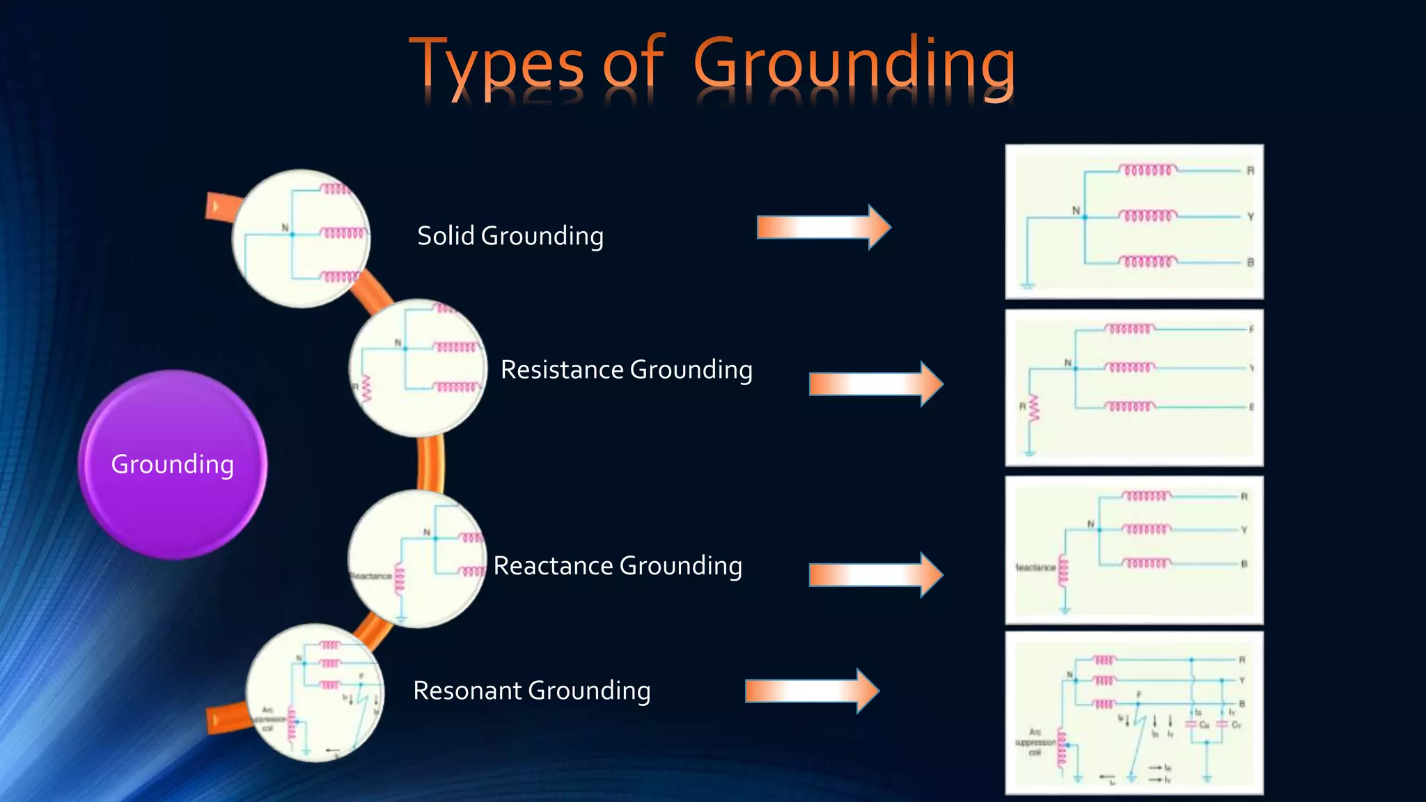
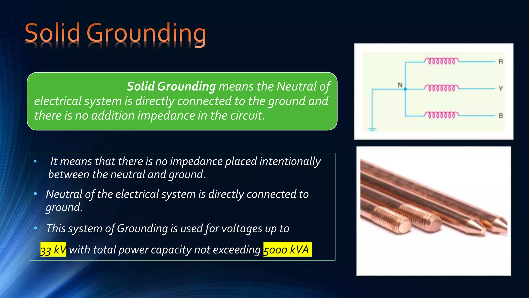
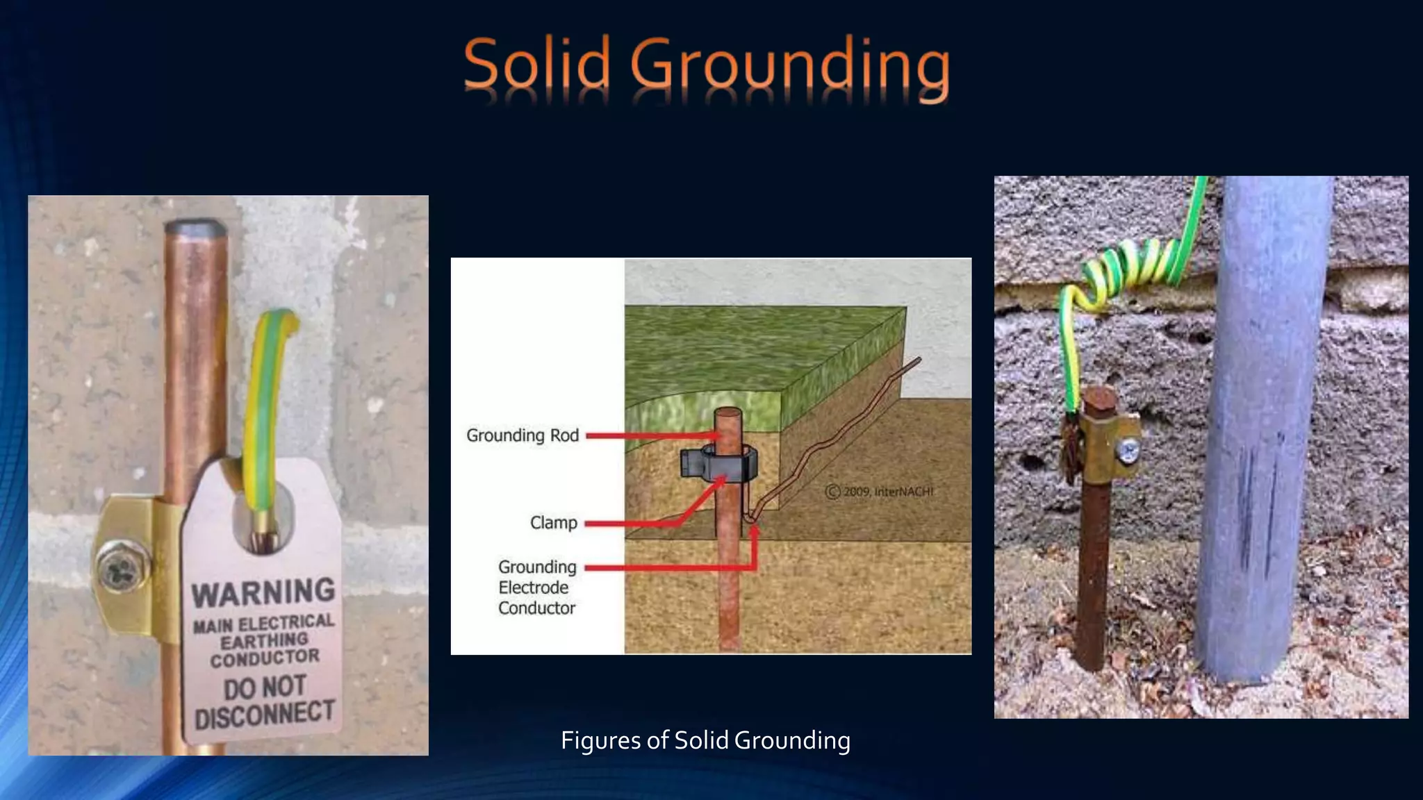
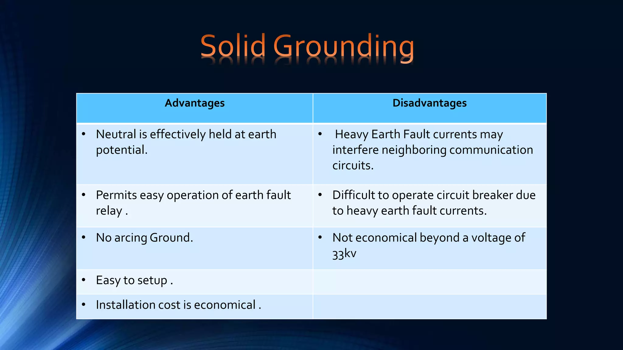
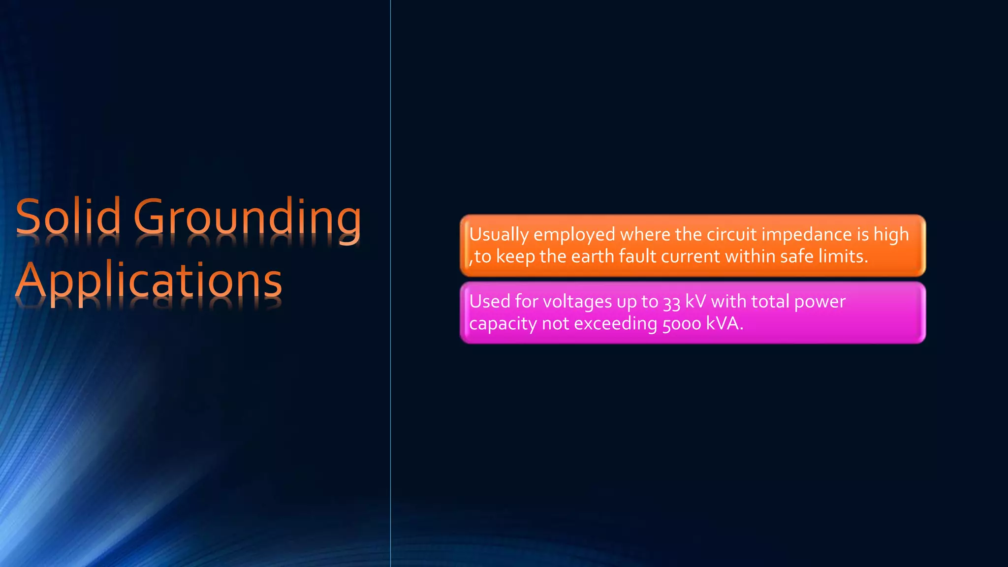
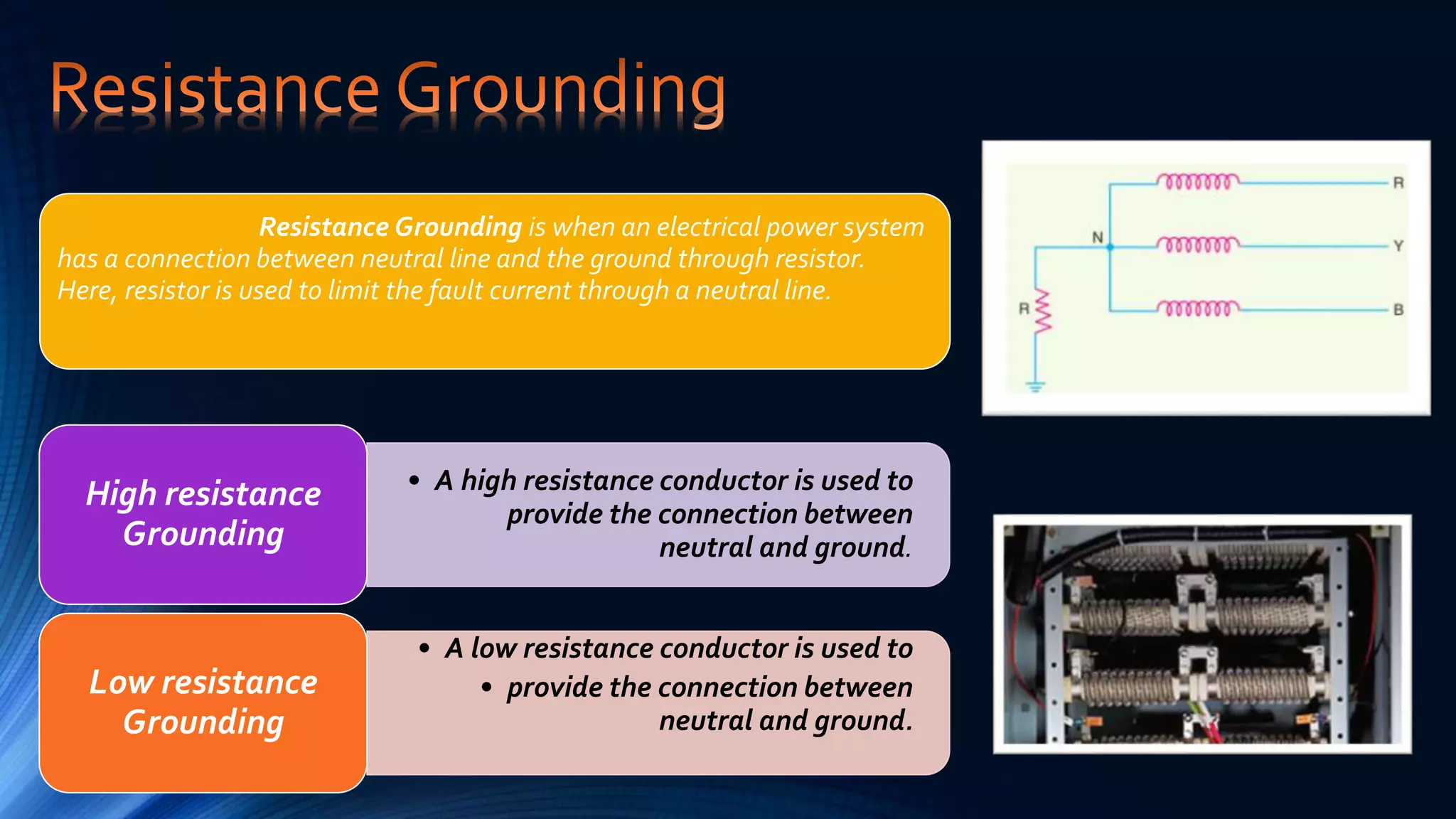
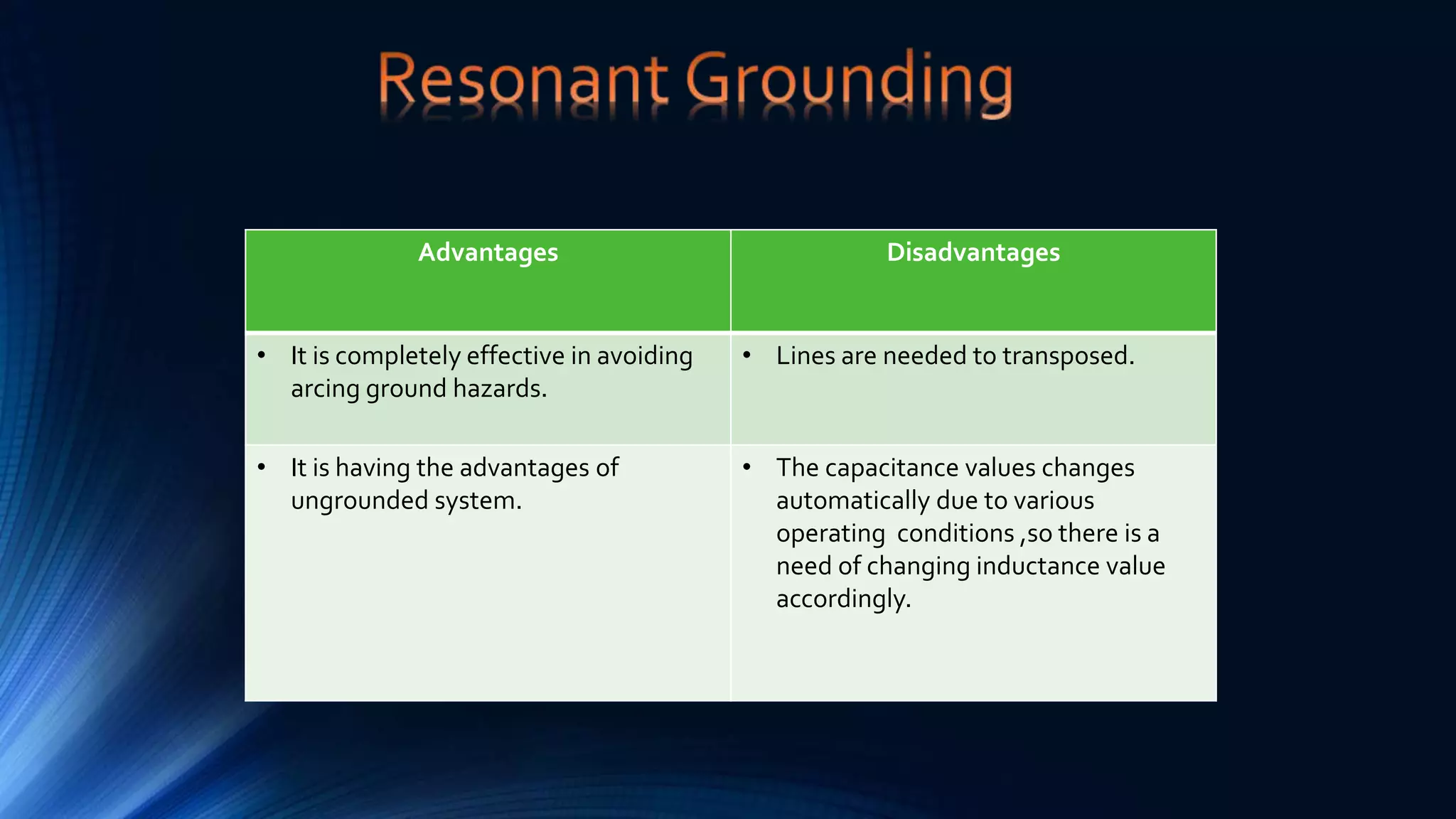
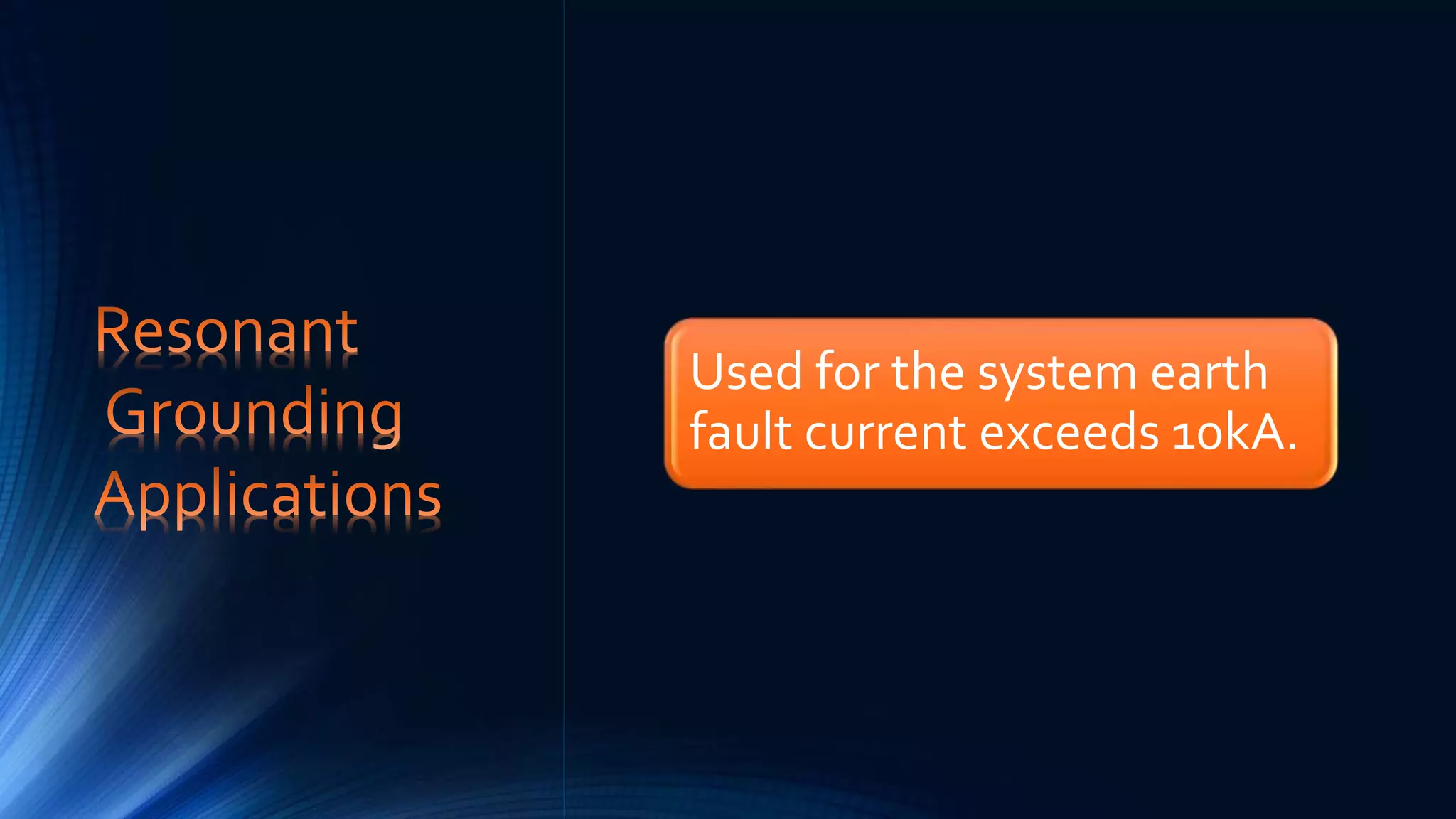
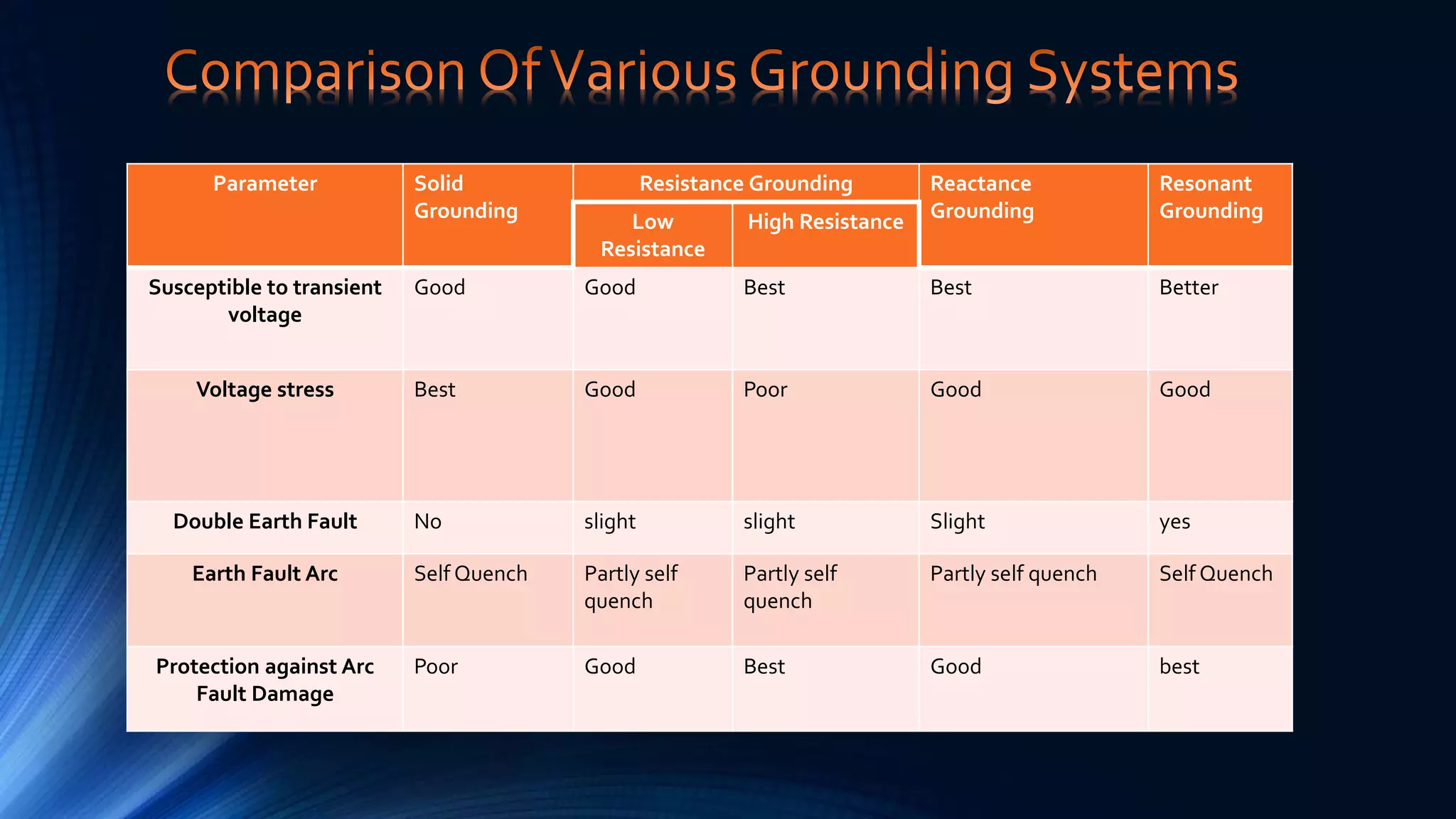
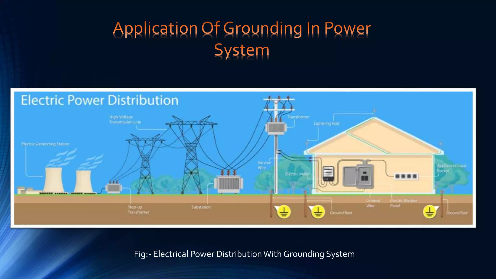
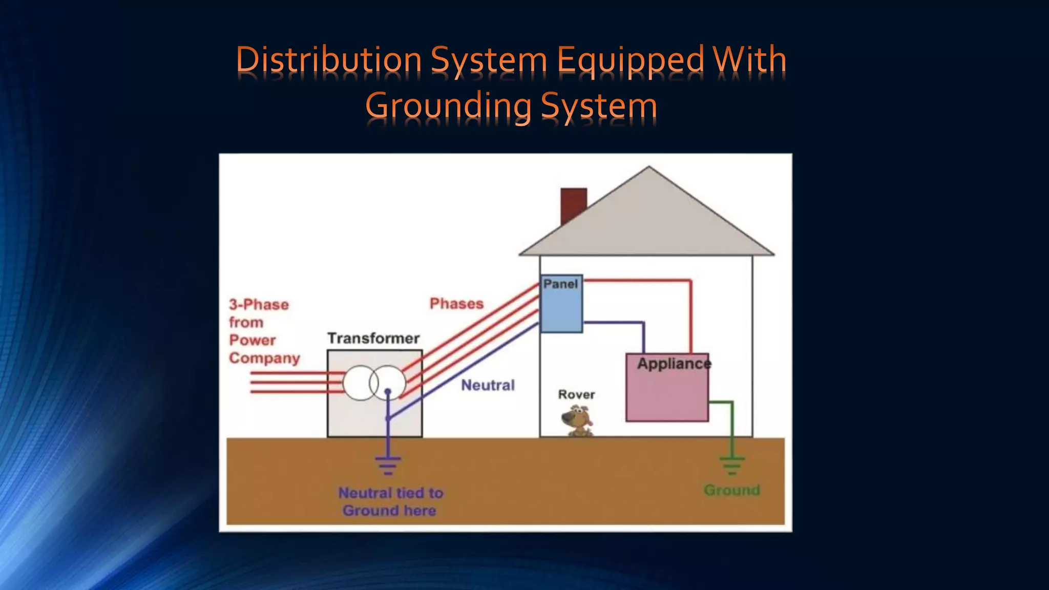
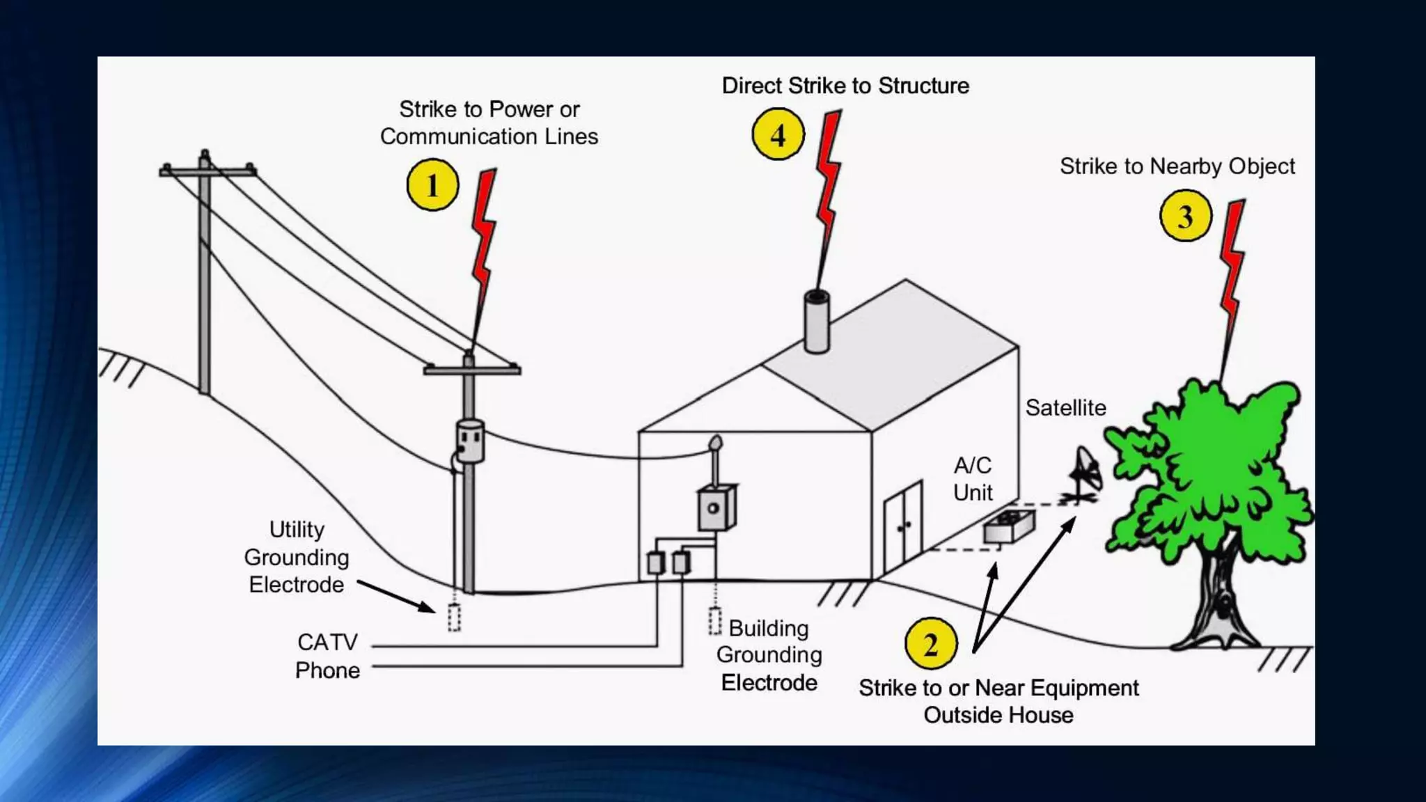
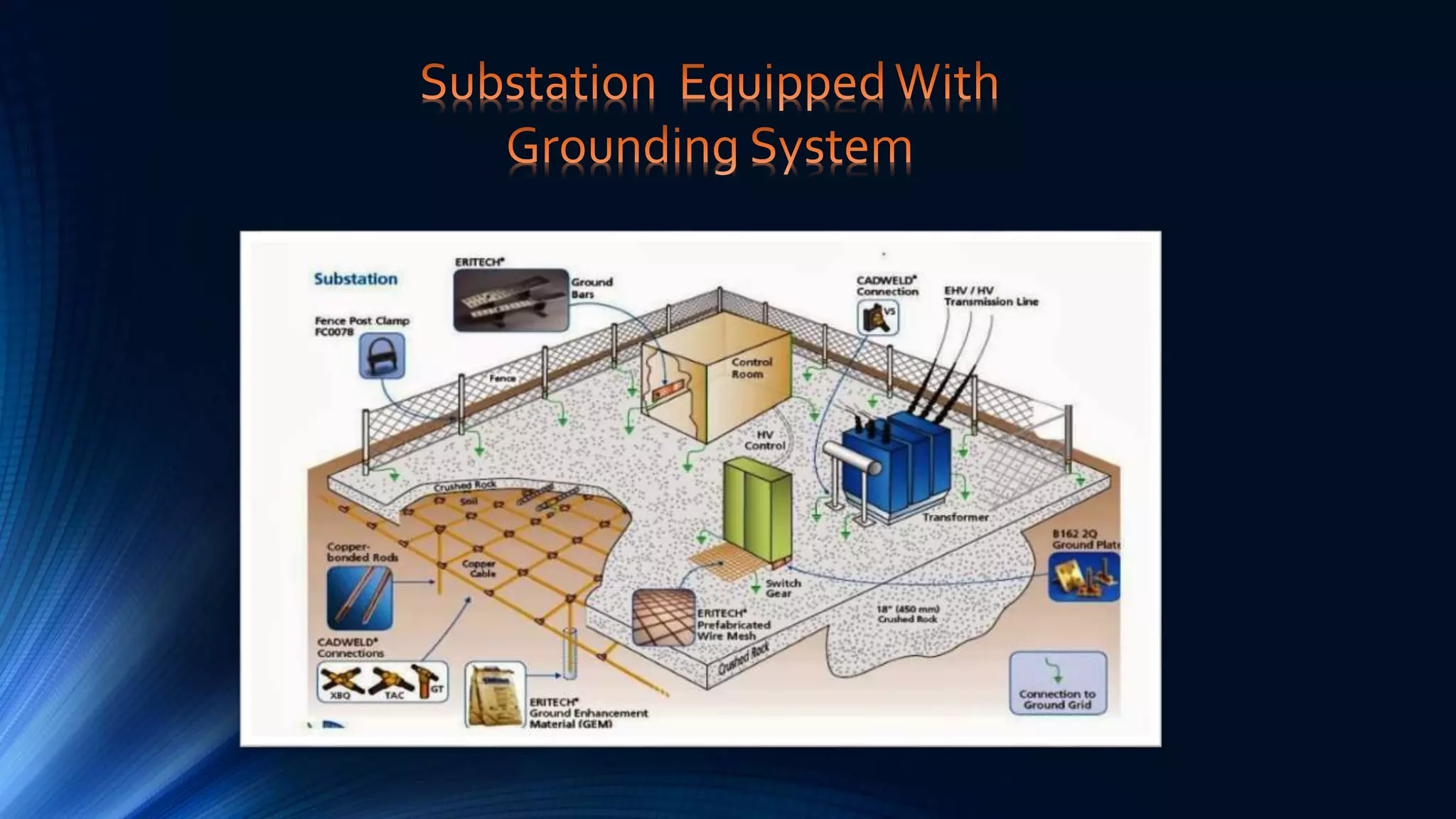
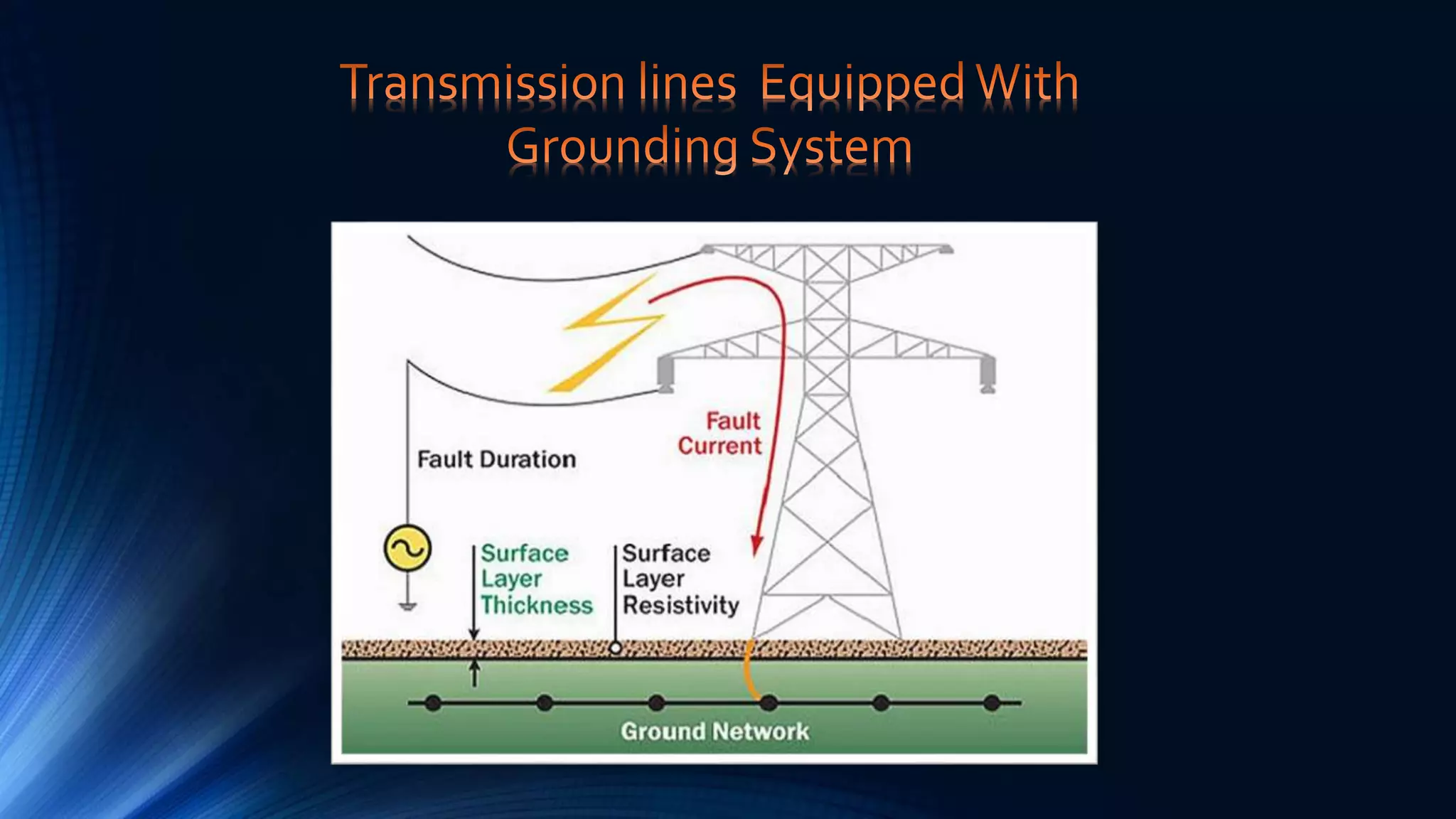
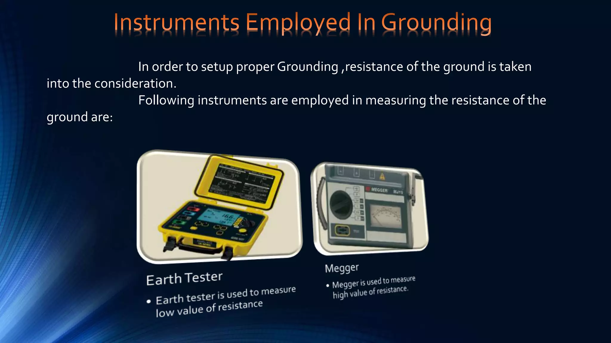
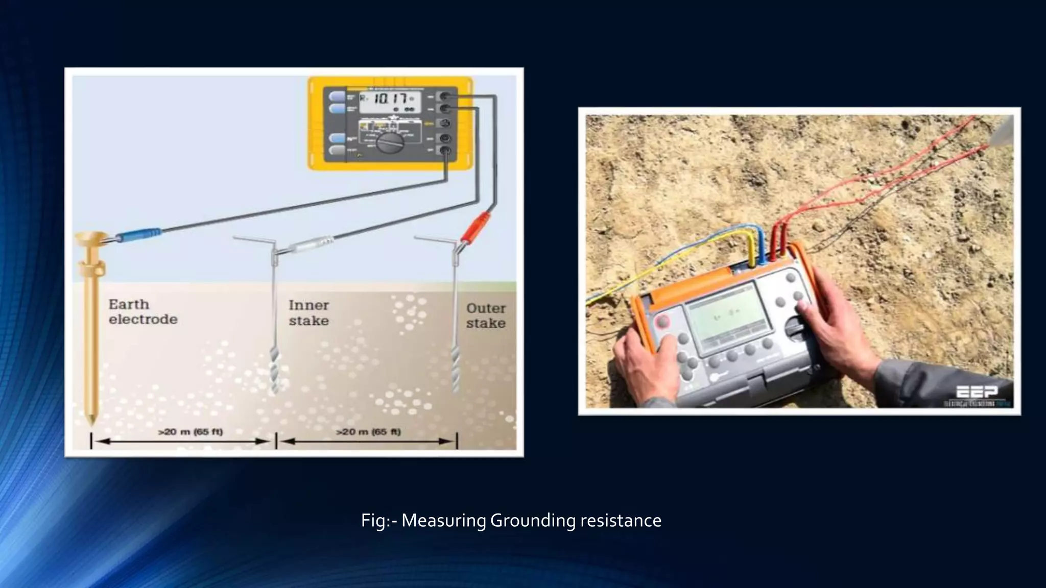
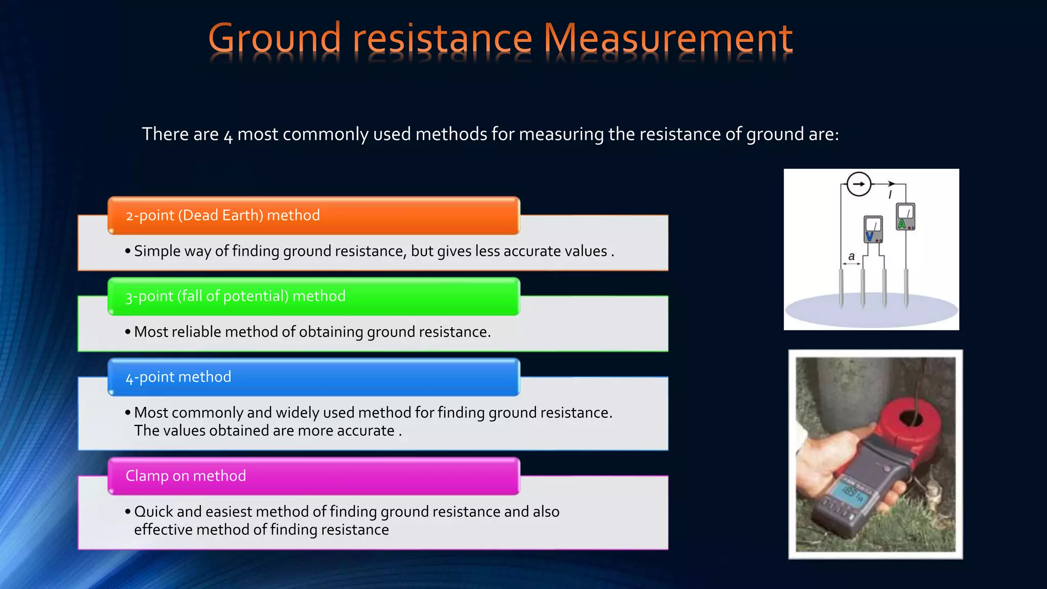
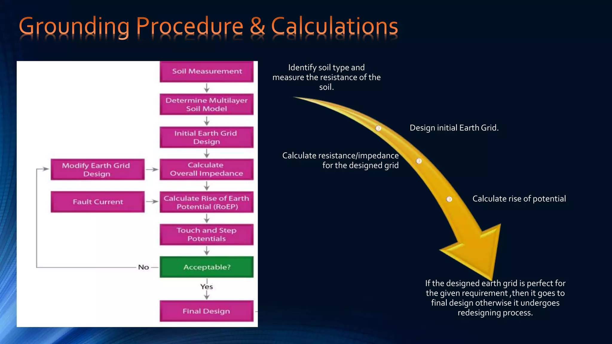
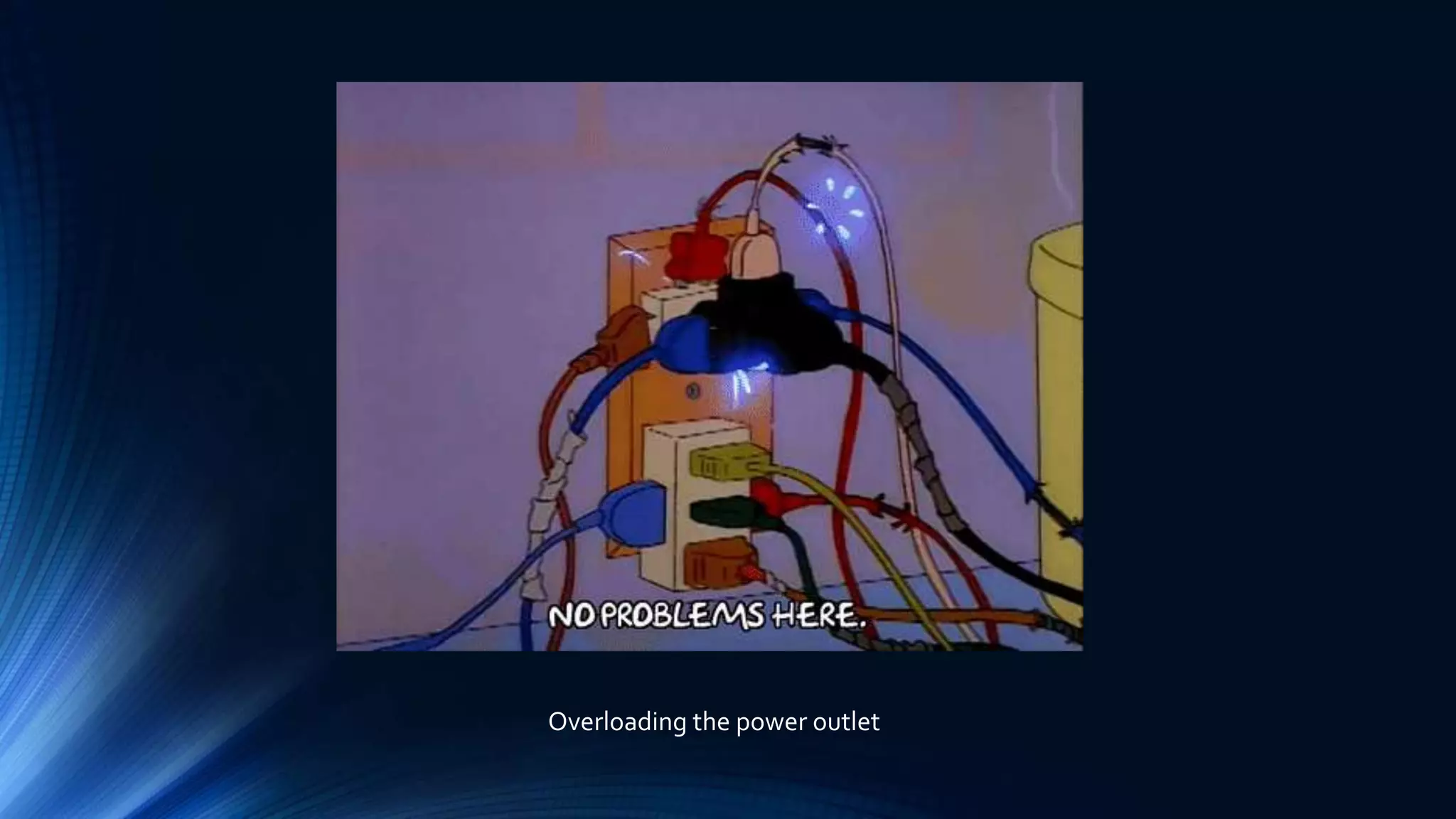
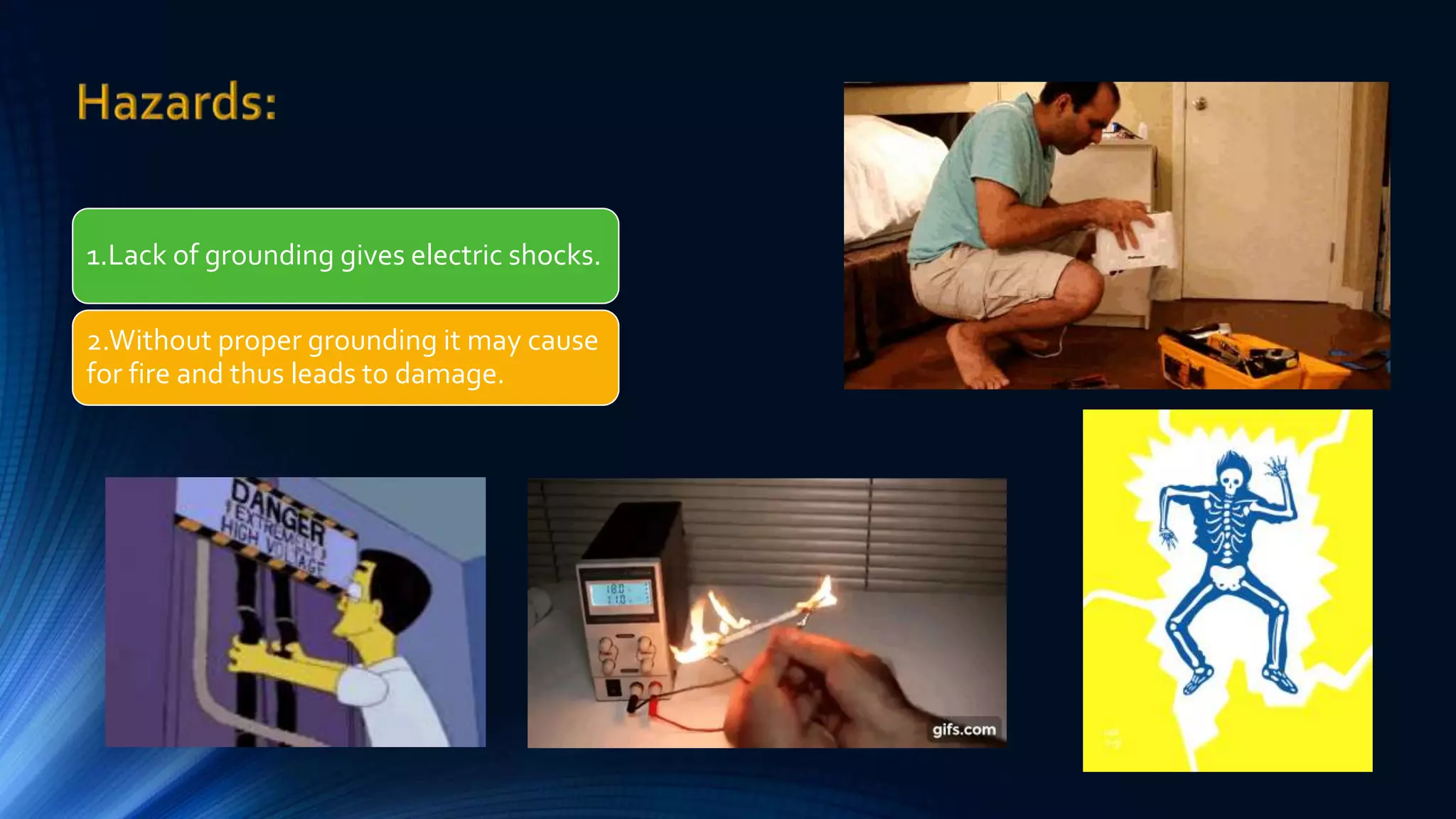
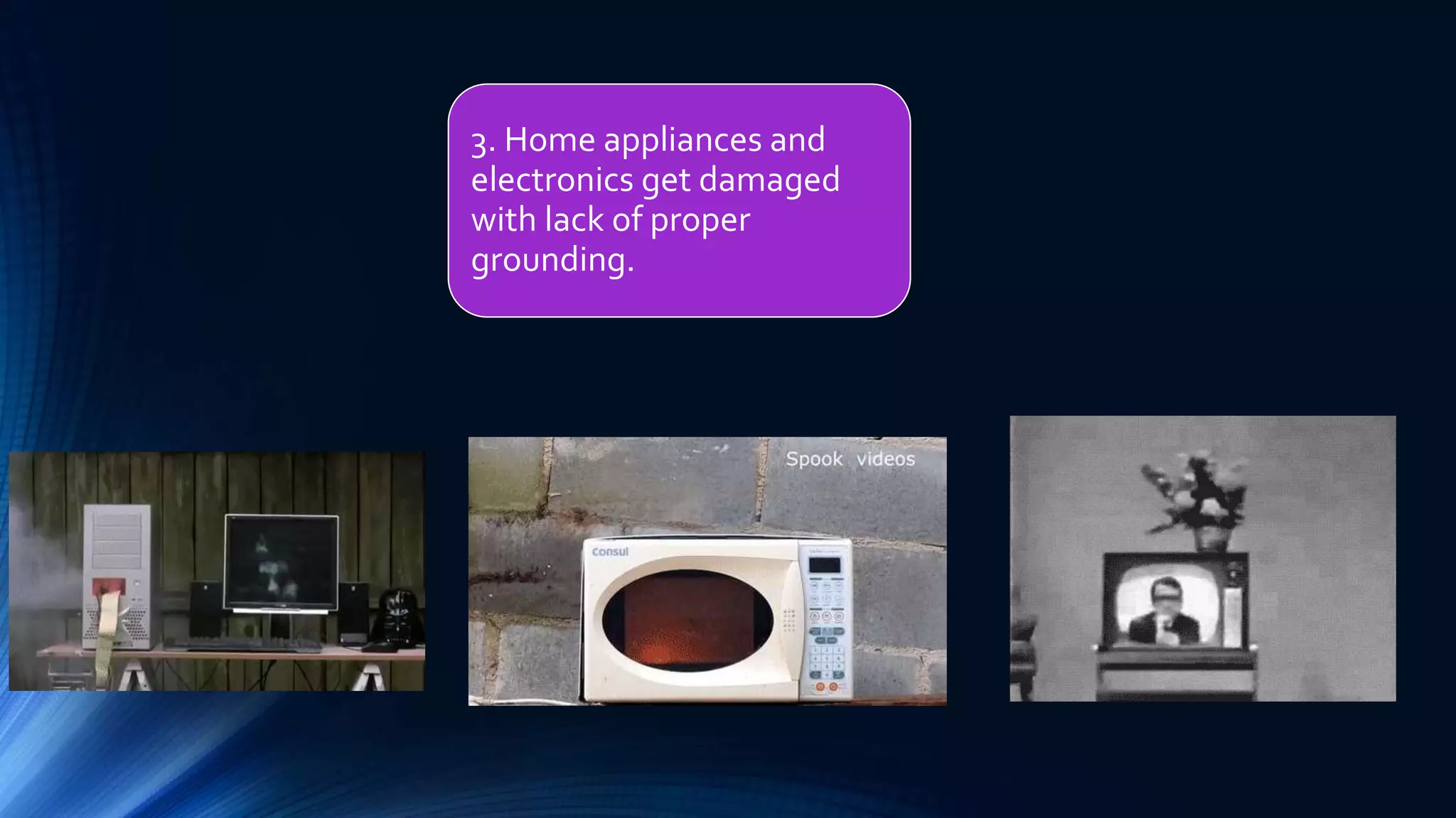
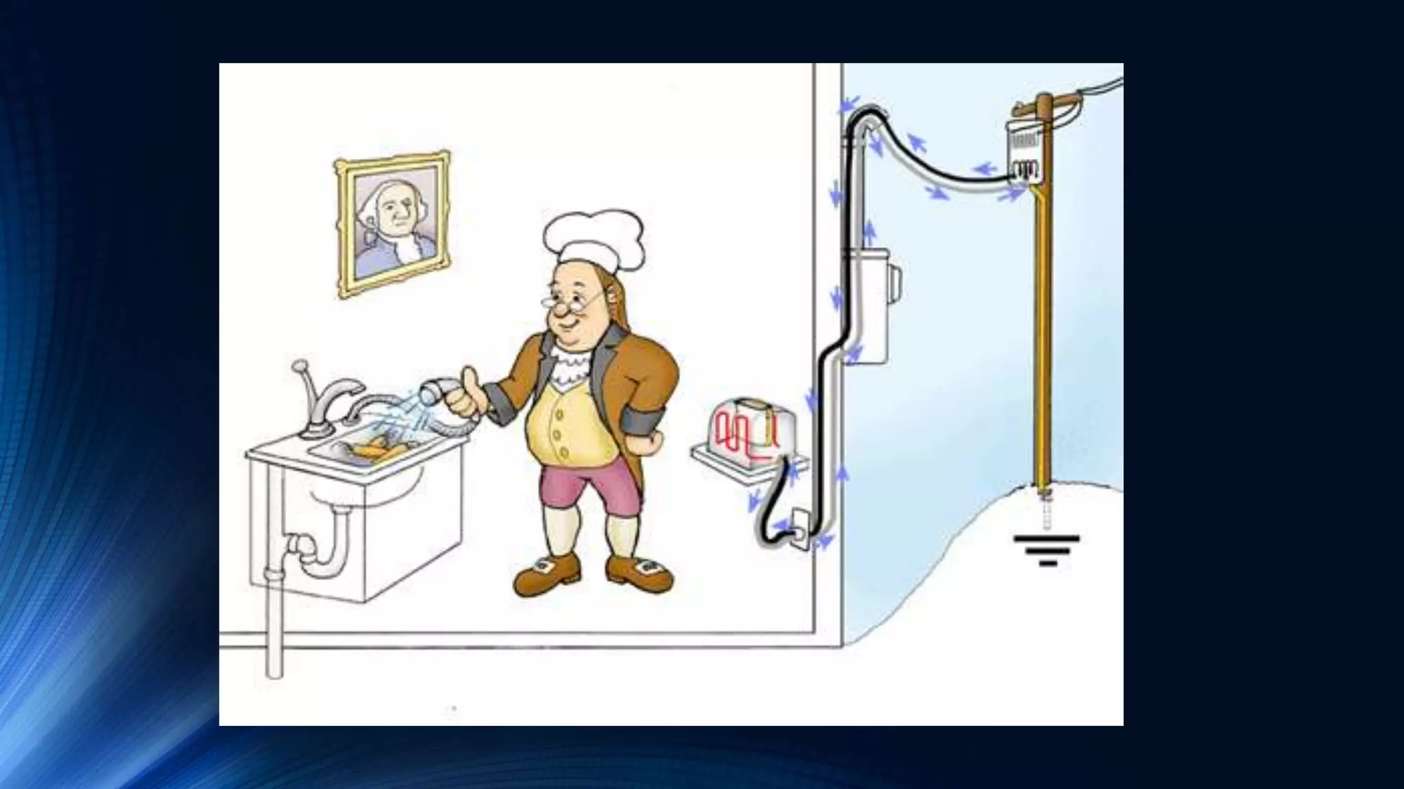
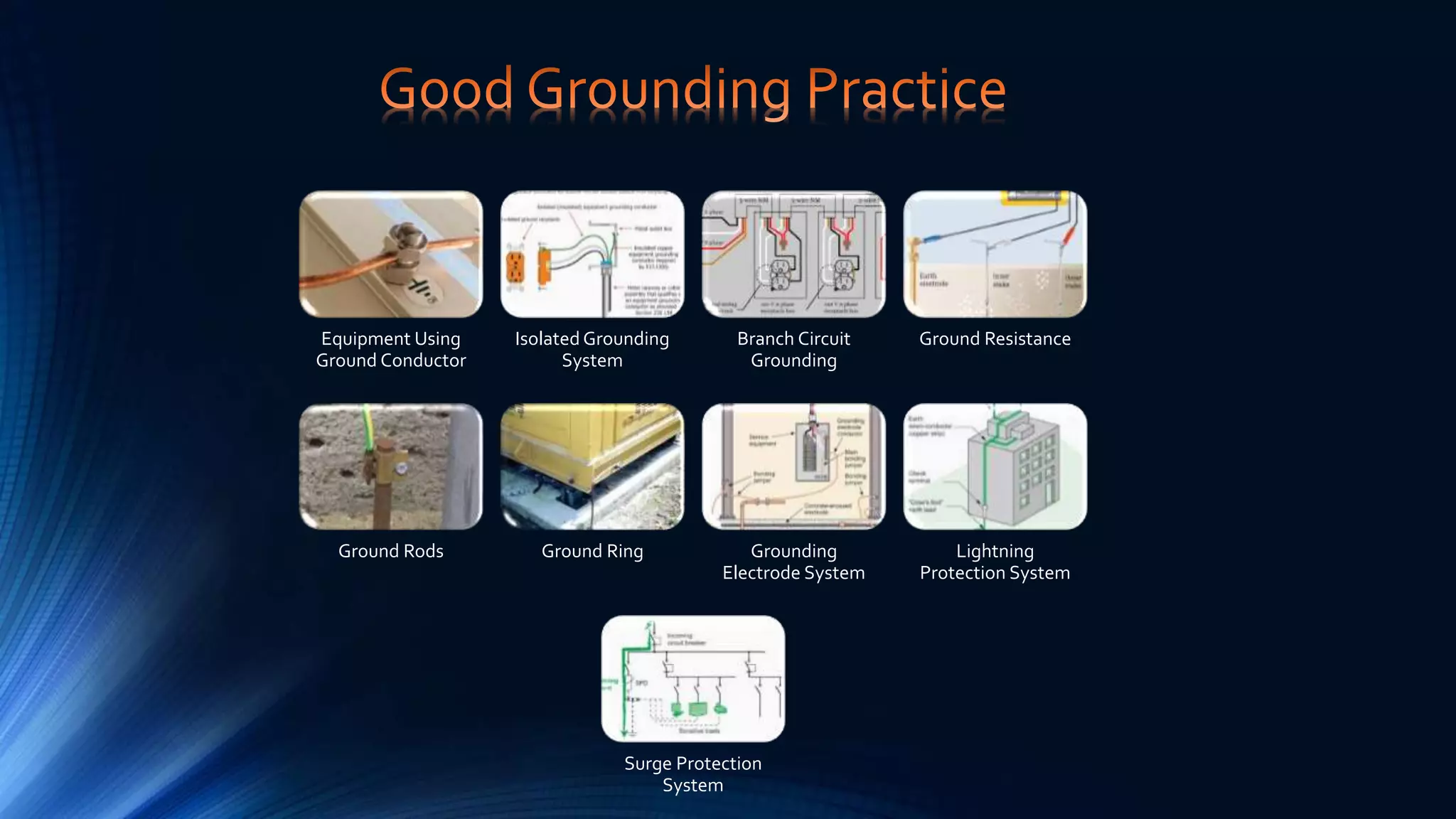
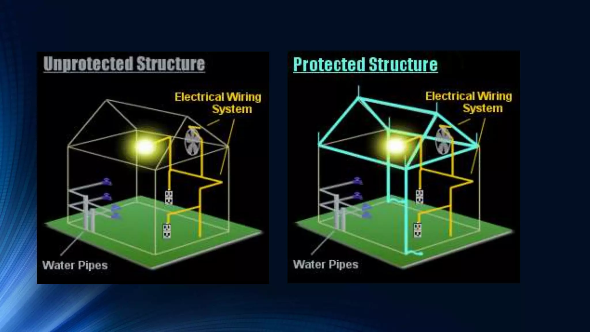
The presentation discusses the importance of grounding in power systems for safety, equipment protection, and building protection from lightning strikes. It covers types of grounding including solid grounding, resistance grounding, reactance grounding, and resonant grounding. Measurement instruments and calculation procedures for proper grounding are also reviewed. Lack of proper grounding can cause electric shocks, fires, and equipment damage. IEEE standards provide guidelines for industrial and commercial grounding systems.


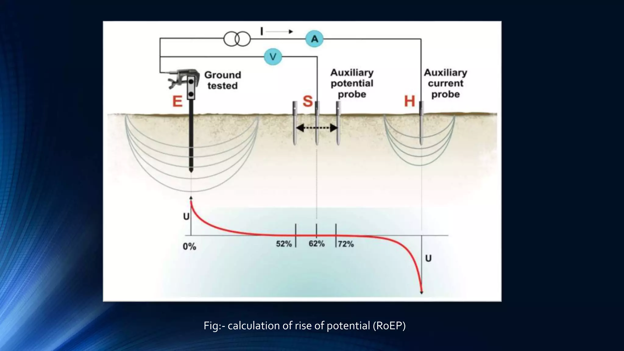


![protection of transmission lines[distance relay protection scheme]](https://cdn.slidesharecdn.com/ss_thumbnails/os-exe3-23-may2011-sr-i-776s21tr-lineprotection-120425095503-phpapp02-thumbnail.jpg?width=640&height=640&fit=bounds)


