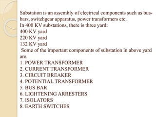
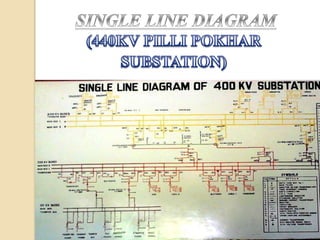
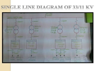
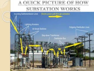
SUBMITTED BY :-
MANISH GUPTA
1006421045
NEHA SINGH
1006421059
PUNEET DHINGRA
1006421066
UZMA UDDIN
1006421108
• Introduction
• Single Line Diagram
•Power Transformer
• A Quick Picture Of How Substation Works
• Lightening Arrestor
• Wave Trap
• Current Transformer
• Potential Transformer
• Circuit Breaker
• Isolator & Earth Switch
• New Instruments
• Conclusion
Electric power is produced at the power generating
stations, which are generally located far away from the
load centers. High voltage transmission lines are used to
transmit the electric power from the generating stations to
the load centers. Between the power generating station and
consumers a number of transformations and switching
stations are required. These are generally known as
substations.
Substations are important part of power system and form a
link between generating stations, transmission systems and
distribution systems.
The generation, transmission and distribution system of
electrical power is called the electrical power supply
system.
Substation is an assembly of electrical components such as bus-
bars, switchgear apparatus, power transformers etc.
In 400 KV substations, there is three yard:
400 KV yard
220 KV yard
132 KV yard
Some of the important components of substation in above yard
are.
1. POWER TRANSFORMER
2. CURRENT TRANSFORMER
3. CIRCUIT BREAKER
4. POTENTIAL TRANSFORMER
5. BUS BAR
6. LIGHTENING ARRESTERS
7. ISOLATORS
8. EARTH SWITCHES
WHAT IS POWER TRANSOFRMER
WORKING PRINCIPLE
PRACTICAL WORKING
MAIN CONSTRUCTION PARTS
PRIMARY WINDING
MAGNETIC CORE
SECONDARY WINDING
• TAP CHANGER
• TANK
• CONSERVATOR
• SILICA GEL BREATHER
• BCHHOLZ RELAY
• DOUBLE DIAPHRANGM EXPLOSION
VENT
• OIL LEVEL INDICATOR
• WINDING TEPERATURE INDICATOR
Lightning Arrestor
Lightening arresters discharge the
over voltage surges to earth and
protect the equipment insulation
from switching surges & lightening
surges. surge arresters are generally
connected between phase conductor
and ground. In a substation surge
arrester is located at the starting of
the substation as seen from
incoming transmission lines and is
the first equipment of the
substation. Surge arrester are also
provided near the transformer
terminals phase to ground
Wave trap is a PLCC (power line
carrier communication)
communication in power system
which block the outer frequency of
other power station these are
installed in switch yard. It is also
known as line trap.
This equipment is installed in the
substation for trapping the high
frequency communication signals
sent on the line from remote
substation and diverting them to
the telecom panel in the substation
control room.
A current transformer (CT) is
used for measurement of
alternating electric currents.
Current transformer, together
with voltage VT is known as
instrument transformers.
The lines in substations carry currents in the order of thousands
of amperes. The measuring instruments are designed for low
value of currents. Current transformers are connected in lines to
supply measuring instruments and protective relays.When current
in a circuit is too high to direct apply to measuring instruments, a
CT produces a reduced current accurately proportional to the
current in the circuit, which can be conveniently connected to
measuring and recording instruments.
The lines in substations operate at high
voltages. The measuring instruments are
designed for low value of voltages.
Potential transformers are connected in
lines to supply measuring instruments
and protective relays. These
transformers make the low voltage
instruments suitable for measurement of
high voltages.
Potential transformer
Circuit breakers are used for
opening or closing a circuit under
normal as well as abnormal
(faulty) conditions.
Different types of CBs which are
generally used are oil circuit
breaker, air-blast circuit breaker,
vacuum circuit breaker and SF6
circuit breaker.
of a short circuit.
SF6 CIRCUIT BREAKER
Isolators are employed in substations
to isolate a part of the system for
general maintenance. Isolator
switches are operated only under no
load condition. They are provided on
each side of every circuit breaker.
Earth switch is used to discharge the
voltage in the circuit to earth for
safety. It is located for each incoming
transmission line and each side of the
bulbar section.
Isolators
Earth switch
When number of lines operating at
the same voltage levels needs to be
connected electrically, bus-bars are
used. Bus-bars are conductors
made of copper or aluminium, with
very low impedance and high
current carrying capacity.
Different types of bus-bar
arrangements are…
single bus bar arrangements, single
bus-bar with sectionalisation,
double bus-bar arrangements, and
ring bus-bar scheme and etc.
500mva transformer750 mva transformer
Now from this report we can conclude that electricity
plays an important role in our life, we made aware of
how the transmission of electricity is done. We also
came to know about the various parts of the substations
system.

Load Distribution

  • 1.
    SUBMITTED BY :- MANISHGUPTA 1006421045 NEHA SINGH 1006421059 PUNEET DHINGRA 1006421066 UZMA UDDIN 1006421108
  • 2.
    • Introduction • SingleLine Diagram •Power Transformer • A Quick Picture Of How Substation Works • Lightening Arrestor • Wave Trap • Current Transformer • Potential Transformer • Circuit Breaker • Isolator & Earth Switch • New Instruments • Conclusion
  • 3.
    Electric power isproduced at the power generating stations, which are generally located far away from the load centers. High voltage transmission lines are used to transmit the electric power from the generating stations to the load centers. Between the power generating station and consumers a number of transformations and switching stations are required. These are generally known as substations. Substations are important part of power system and form a link between generating stations, transmission systems and distribution systems. The generation, transmission and distribution system of electrical power is called the electrical power supply system.
  • 4.
    Substation is anassembly of electrical components such as bus- bars, switchgear apparatus, power transformers etc. In 400 KV substations, there is three yard: 400 KV yard 220 KV yard 132 KV yard Some of the important components of substation in above yard are. 1. POWER TRANSFORMER 2. CURRENT TRANSFORMER 3. CIRCUIT BREAKER 4. POTENTIAL TRANSFORMER 5. BUS BAR 6. LIGHTENING ARRESTERS 7. ISOLATORS 8. EARTH SWITCHES
  • 7.
    WHAT IS POWERTRANSOFRMER WORKING PRINCIPLE PRACTICAL WORKING MAIN CONSTRUCTION PARTS PRIMARY WINDING MAGNETIC CORE SECONDARY WINDING
  • 8.
    • TAP CHANGER •TANK • CONSERVATOR • SILICA GEL BREATHER • BCHHOLZ RELAY • DOUBLE DIAPHRANGM EXPLOSION VENT • OIL LEVEL INDICATOR • WINDING TEPERATURE INDICATOR
  • 10.
    Lightning Arrestor Lightening arrestersdischarge the over voltage surges to earth and protect the equipment insulation from switching surges & lightening surges. surge arresters are generally connected between phase conductor and ground. In a substation surge arrester is located at the starting of the substation as seen from incoming transmission lines and is the first equipment of the substation. Surge arrester are also provided near the transformer terminals phase to ground
  • 11.
    Wave trap isa PLCC (power line carrier communication) communication in power system which block the outer frequency of other power station these are installed in switch yard. It is also known as line trap. This equipment is installed in the substation for trapping the high frequency communication signals sent on the line from remote substation and diverting them to the telecom panel in the substation control room.
  • 12.
    A current transformer(CT) is used for measurement of alternating electric currents. Current transformer, together with voltage VT is known as instrument transformers. The lines in substations carry currents in the order of thousands of amperes. The measuring instruments are designed for low value of currents. Current transformers are connected in lines to supply measuring instruments and protective relays.When current in a circuit is too high to direct apply to measuring instruments, a CT produces a reduced current accurately proportional to the current in the circuit, which can be conveniently connected to measuring and recording instruments.
  • 13.
    The lines insubstations operate at high voltages. The measuring instruments are designed for low value of voltages. Potential transformers are connected in lines to supply measuring instruments and protective relays. These transformers make the low voltage instruments suitable for measurement of high voltages. Potential transformer
  • 14.
    Circuit breakers areused for opening or closing a circuit under normal as well as abnormal (faulty) conditions. Different types of CBs which are generally used are oil circuit breaker, air-blast circuit breaker, vacuum circuit breaker and SF6 circuit breaker. of a short circuit. SF6 CIRCUIT BREAKER
  • 15.
    Isolators are employedin substations to isolate a part of the system for general maintenance. Isolator switches are operated only under no load condition. They are provided on each side of every circuit breaker. Earth switch is used to discharge the voltage in the circuit to earth for safety. It is located for each incoming transmission line and each side of the bulbar section. Isolators Earth switch
  • 16.
    When number oflines operating at the same voltage levels needs to be connected electrically, bus-bars are used. Bus-bars are conductors made of copper or aluminium, with very low impedance and high current carrying capacity. Different types of bus-bar arrangements are… single bus bar arrangements, single bus-bar with sectionalisation, double bus-bar arrangements, and ring bus-bar scheme and etc.
  • 17.
  • 18.
    Now from thisreport we can conclude that electricity plays an important role in our life, we made aware of how the transmission of electricity is done. We also came to know about the various parts of the substations system.