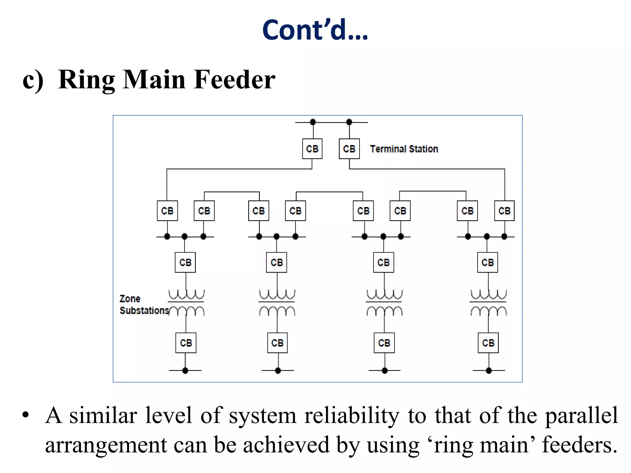
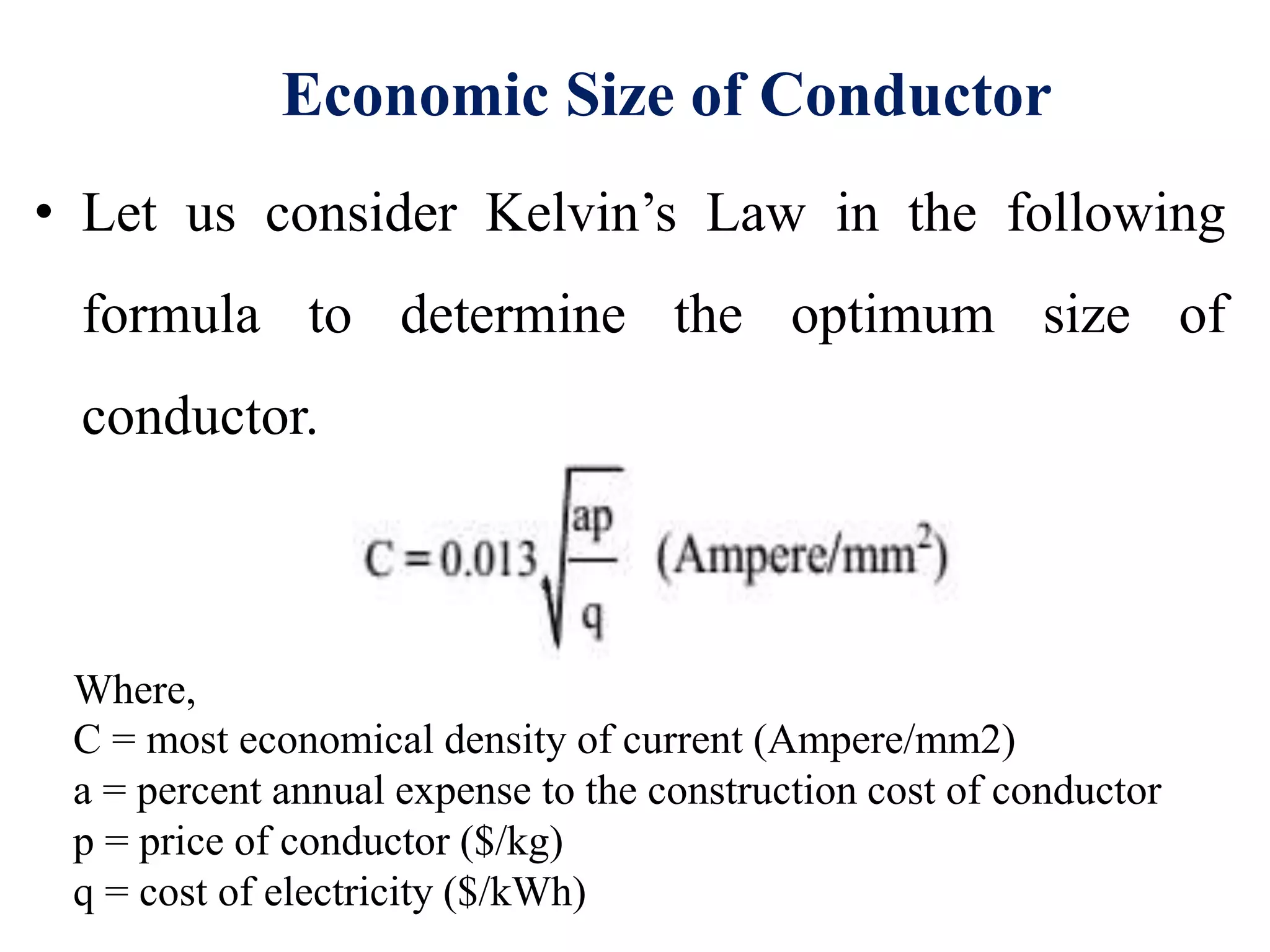
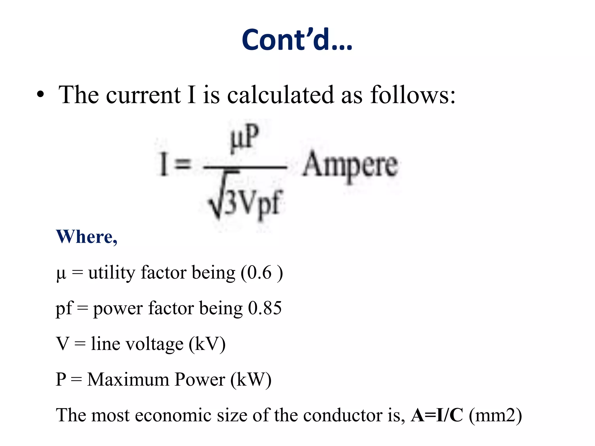
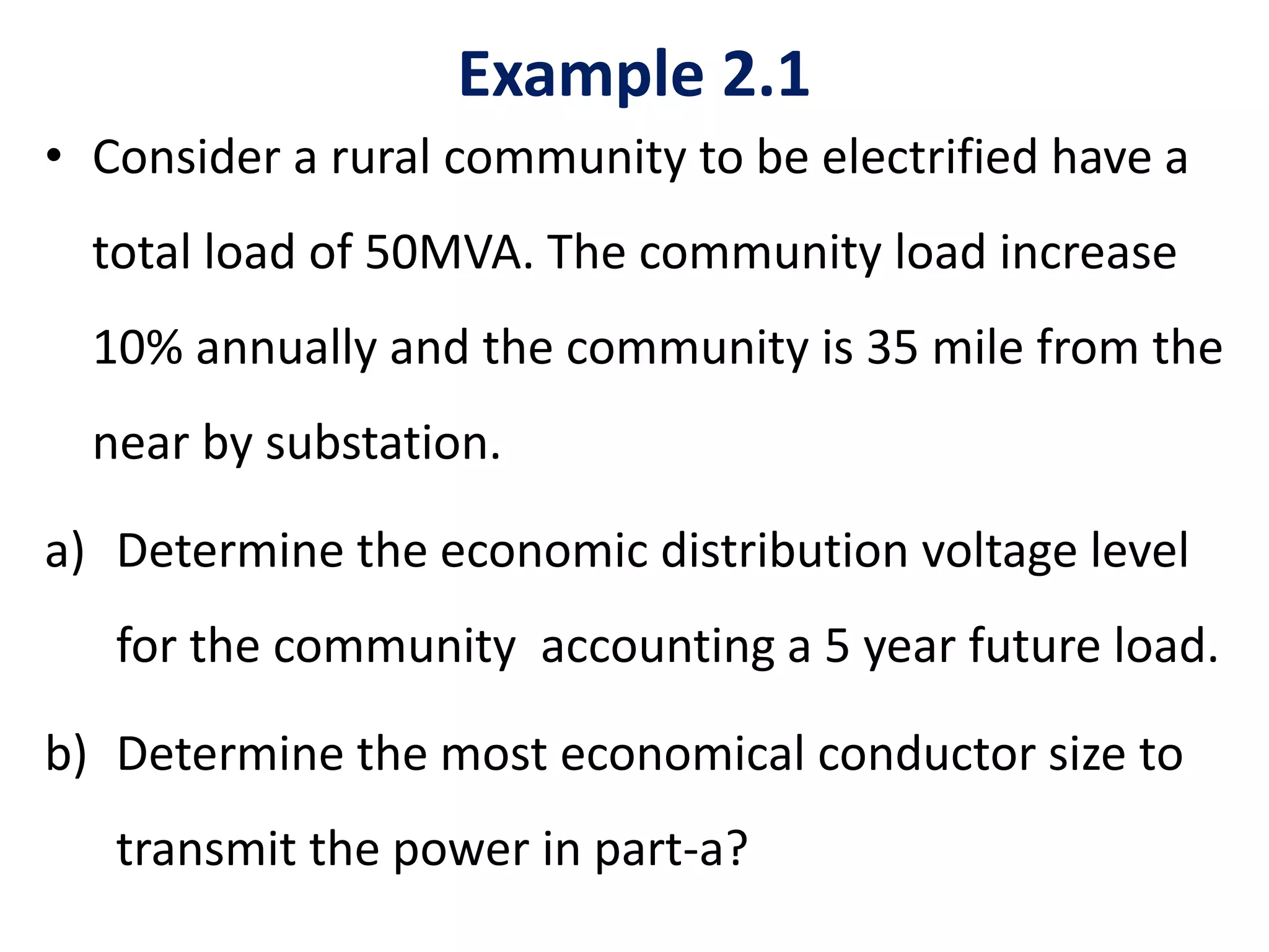
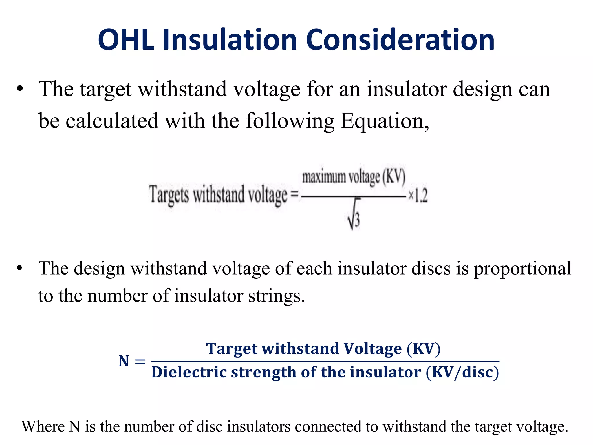
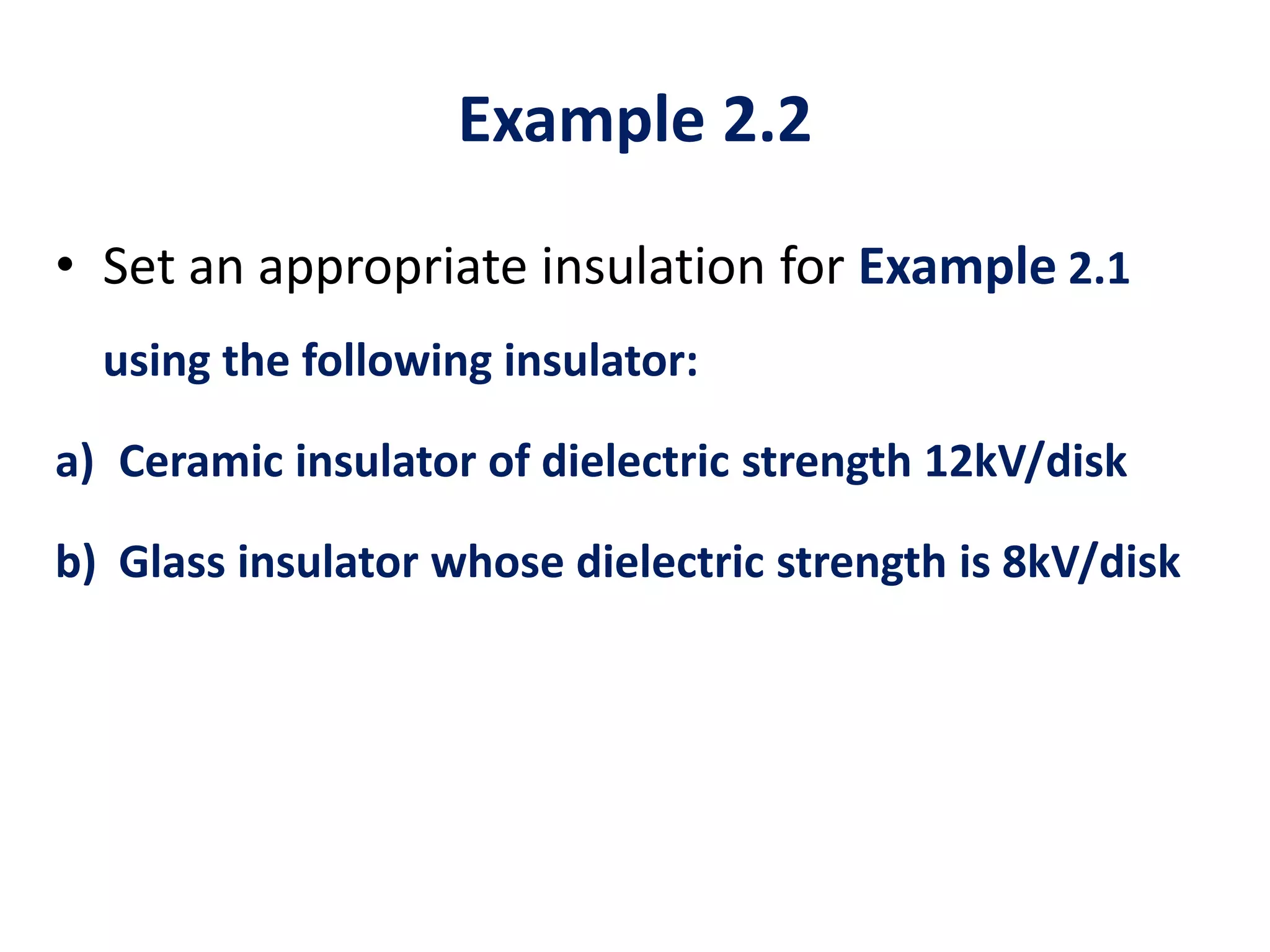
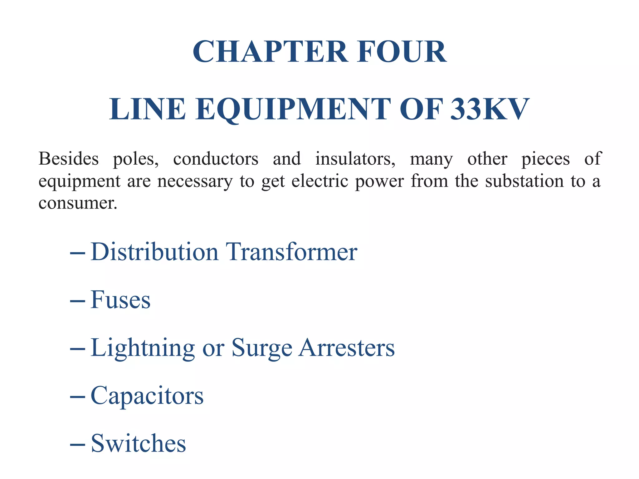
1. The document provides an overview of a training module on overhead line work. It covers power system structure, design principles of distribution lines, and installing/maintaining electrical equipment.
2. The objectives are to address distribution line problems, energize 33kV lines, develop awareness of installing/maintaining 33kV lines, and discuss insulation and equipment selection.
3. The target group are trainees in categories S1-S4 and W3-W6.
This document discusses cable sizing calculations and techniques. It explains that proper cable sizing is important to ensure efficient, safe and economic transmission of electrical energy without interruptions or exceeding the cable's limits. The document outlines the common steps for cable sizing: 1) gathering data on the cable, load and installation conditions, 2) determining the minimum size based on current capacity, voltage drop, temperature rise and fault impedance, and 3) selecting the optimally sized cable. Several examples are provided to illustrate implementing the cable selection process. Risks of improper sizing like voltage drops, overheating and shorter lifespan are also summarized.
Transmission & distribution of electrical powerpriyanka1432
This document provides an overview of the course "Transmission & Distribution of Electrical Power" which is divided into 8 modules. Module I introduces basics of power transmission including the necessity of transmitting electricity over long distances at high voltages to reduce losses. It also covers classifications of different transmission systems. Subsequent modules cover components of transmission lines such as conductors, insulators, and their characteristics as well as transmission line parameters and performance. Later modules address extra high voltage transmission, distribution system components, underground cables, and substations.
The document discusses substations and their components. It defines a substation as an assembly of apparatus that transforms electrical energy from one form to another, such as changing voltage levels. Substations contain step-up transformers to increase voltage for transmission and step-down transformers to decrease voltage for distribution to consumers. The document describes various types of substations and explains their functions. It also provides details about components within substations such as circuit breakers, transformers, buses, isolators and instrument transformers.
Complete details of EHV Transmission Line. Consolidated this presentation from those experts who had contributed separately on slider share and other web pages.Thanks for their valuable inputs.
This document discusses high voltage substation design, applications, and considerations. It provides an overview of substation basics, electrical configurations, physical design, protection and controls, and coordination of design and construction. The presentation covers typical substation voltage levels, configurations such as ring bus and breaker-and-a-half, factors to consider in the design process such as service conditions and studies required, and reliability comparisons of different configurations. Design guidelines for spacing and clearances are also presented.
This document discusses the testing and maintenance of power transformers. It outlines the various routine tests performed on transformers according to standards, including winding resistance measurement, insulation resistance measurement, high voltage tests, no load and load loss measurements. It also describes type tests such as lightning impulse and short circuit tests. Finally, it discusses the importance of preventive maintenance through regular checks of oil levels, insulation resistance, bushings, connections and other components.
This document provides information on a Power System Protection course taught at Vivekanandha College of Engineering for Women. The syllabus covers 5 units: introduction to protection schemes, relay operating principles and characteristics, apparatus protection, theory of circuit interruption, and circuit breakers. It lists textbooks and presents details on each unit, including topics like relay types, transformer/generator/motor protection, arc phenomena, and different circuit breaker types. The last section provides references for textbooks, websites, and presentations on related topics.
The document summarizes key aspects of transmission line design and components. It discusses the methodology for designing transmission lines, including gathering design data, selecting reliability levels, and calculating loads. It also covers the selection and design of various transmission line components such as conductors, insulators, towers, and grounding systems. Design considerations include voltage levels, safety clearances, mechanical requirements, and optimization of costs.
Installation, Testing and Troubleshooting of TransformersLiving Online
The document discusses the installation, testing, and troubleshooting of transformers. It describes the different types of tests performed on transformers, including routine tests, type tests, and special tests. Routine tests check characteristics like winding resistance, voltage ratios, losses, and insulation. Special tests examine properties such as dielectric strength, capacitance, and harmonics. The document also outlines standards and procedures for testing, as well as limits for temperature rise and requirements for insulating oil.
The document discusses the distribution system which distributes electric power from substations to consumers. It has three main components: feeders which connect substations to distribution areas, distributors which supply power to consumers with tappings, and service mains which connect distributors to consumer terminals. Distribution systems can be AC or DC, overhead or underground, and configured radially, in a ring main, or interconnected for reliability. Design considerations for feeders include current capacity, conductor type, distance from substation, and cost.
Transmission lines have four parameters that characterize them: resistance, inductance, capacitance, and conductance. These distributed parameters determine the power carrying capacity and voltage drop across the line. Short lines only consider the series resistance and inductance, while medium and long lines must also account for the distributed shunt capacitance. The resistance of overhead transmission lines is affected by factors like skin effect, temperature, bundling of conductors, and proximity effect between phases.
UNIT - 05 DISTRIBUTION LINES AND TRANSFORMER CENTREPremanandDesai
Code of practice for Distribution Lines and Transformer centre, types of transformer centres -
Pole mounted, plinth mounted, indoor and outdoor types. Determining the rating of
Distribution Transformer. Write Specifications of the Distribution Transformer. Draw the
SLD of a Transformer centre indicating the size of protective devices, Prepare the schedule of
equipments /Materials with specifications for a 11KV/415V,100 KVA transformer centre and
their estimates, 415 V LT line materials and specifications , method of calculating various LT
line materials (only). Prepare the schedule of materials (only) for 3 phase 4 wire LT line,
11 KV HT Line-materials and their specifications, method of calculating various HT line
materials and tapping structure, TOPO sheet and its use, Concept of combined estimates.
Prepare the schedule of materials (only) for 11 KV single circuit HT line for Rural
Electrification.
(Note: HT lines over head type only)
This document provides information about transmission towers. It begins with definitions of transmission towers and pylons. It then discusses different types of transmission towers, including those for HVAC, HVDC, and railway lines. It also covers towers for different current types. The document discusses factors that determine tower design, such as height, base width, and cross arm length. It provides formulas for calculating spacing between conductors and clearances. Finally, it briefly discusses tower erection methods.
This is the simple ppt explaining about the main components of the power systems. especially we are determining the insulators and its types with real time pictures which are attractive,
A brief about 33kv Substation........
like and share.................
want some help in your ppt or in any project visit..
https://www.fiverr.com/dawachya
This presentation provides an overview of substations, including their classification, components, and functions. It discusses the different types of substations such as transformer substations, pole-mounted substations, and underground substations. Transformer substations are classified as step-up, primary grid, secondary, and distribution substations based on their voltage levels. Pole-mounted substations are constructed on poles for distribution. Underground substations are used in congested areas with limited space. The presentation also describes key equipment in substations like circuit breakers, transformers, isolators, and their protective functions.
Design of a generating substation with the description of designing a transformer. Here we show some basic components of a substation. and we also show the parameters and calculation to design a transformer of a specific ratings.
Cables are often the last component considered during system design even if in many situations cables are the true system’s lifeline: if a cable fails, the entire system may stop. Cable reliability is therefore extremely important, then a cable system should be engineered to last the life of the system in the installation environment for the required application. Environments in which cable systems are being used are often challenging, as extreme temperatures, chemicals, abrasion, and extensive flexing. These variables have a direct impact on the materials used for cable insulation and jacketing as well as the construction of the cable. Using a systematic approach will help ensure that designer select the best cable for the required application in the installation environment. This lessons will provide students main guidelines for perform this approach.
Electrical Transmission Tower: Types, Design and PartsDr.Raja R
This document discusses electrical transmission towers, including their purpose, parts, design considerations, and types. It notes that transmission towers carry high voltage power lines from generating stations to substations and must sustain heavy conductors and natural calamities. The key parts of a transmission tower are identified as the peak, cross arms, boom, cage, body, legs, and baseplate assembly. Design considerations include ground clearance, insulator length, conductor spacing and clearance, and midspan clearance. Towers are classified by angle of deviation as A, B, C, or D type and by force application as tangent suspension or angle towers. Special towers include those for river, railway, or highway crossings and transposition.
Underground cables consist of one or more insulated conductors surrounded by protective layers. They are used to transmit electric power underground, which ensures continuous power supply with less maintenance compared to overhead lines. Common types include low, high, and extra high tension cables. Cables have conducting cores insulated and surrounded by a metallic sheath, bedding, armouring and serving for protection. Screened and belted cables are used for 3-phase underground transmission up to 66kV, while pressure cables are used above 66kV.
The document describes the electric power supply system from generation to distribution. Electric power is generated at power stations and transmitted through high voltage transmission lines over large distances before being distributed to consumers through lower voltage distribution lines. The key components of the system include generation stations, transmission lines, distribution systems, substations to step-up and step-down voltages, and overhead or underground lines.
The document is a presentation on the Liluah 132/33/25 KV substation in West Bengal. It includes acknowledgments, a single line diagram of the substation, and sections covering various equipment found at the substation like electrical busbars, protective relay schemes, lightning protection, isolators, capacitor banks, powerline carrier communication, batteries, earth transformers, traction transformers, station service transformers, and power transformers. Technical specifications are provided for some of the major equipment.
The document discusses underground power cables. It describes the components of underground cables including conductors, insulation, metallic sheathing, bedding, armoring and serving. The main types of underground cables are discussed - solid cables like belted and screened cables used up to 66kV, and pressurized oil and gas cables used at higher voltages. Methods of laying cables underground include direct burying, draw-in systems using ducts, and solid systems within troughs. Underground cables have advantages over overhead lines like better appearance and reliability, but also challenges like higher installation costs and fault localization difficulties.
This document provides details on substation layout and busbar arrangements. Part A discusses substation layout, including a single line diagram and descriptions of common switchyard accessories like lightning arrestors, CVTs, isolators, circuit breakers, transformers, and other equipment. It also covers PLCC and SCADA systems. Part B covers various busbar arrangements like the single bus system, double bus system, one and a half breaker system, and ring main bus system. It discusses the advantages and disadvantages of each configuration. In summary, the document is a technical report that outlines and compares different substation and busbar designs.
This document provides an overview of HVDC (high voltage direct current) fundamentals. It discusses how HVDC transmission works, the technical advantages it provides over AC transmission such as higher power capacity per conductor and smaller tower size. It also discusses some economic considerations, noting that HVDC has lower line costs but more expensive converter stations, with a typical break-even distance of 500-800 km for overhead lines. Different HVDC system configurations like monopolar and bipolar links are also introduced.
This document compares DC and AC power transmission. It discusses the advantages and disadvantages of each system. DC transmission has advantages like requiring only two conductors, less voltage drops, and no skin effect. However, it has disadvantages like power cannot be generated at high DC voltages. AC transmission can generate and step up power to high voltages more easily using transformers, but has disadvantages like increased resistance from skin effect. Nowadays, power is almost exclusively transmitted using high voltage AC systems due to their advantages over long-distance transmission.
PPT_1_Electrical services_By group no. 1.pptxayazkhan261
Electrical power is generated at power plants and transmitted through high-voltage transmission lines to reduce losses. At substations, the voltage is stepped down for distribution. India's national grid interconnects five regional grids. Power flows from high-voltage transmission networks through distribution transformers and lines to consumers at various voltage levels. Common cable types include ACSR and armored cables. Protection devices isolate faulty sections to maintain reliability while overcurrent, differential and distance schemes detect faults.
The document discusses the transmission and distribution system for electricity. It describes how electricity is generated, transmitted through high voltage transmission lines, and then distributed to homes and businesses through lower voltage distribution lines. The distribution system is made up of substations, utility poles, wires, transformers, and other equipment to safely deliver power. It also discusses the different types of distribution systems and equipment used like primary and secondary distribution, overhead vs. underground lines, and components like poles, wires, transformers, and protective devices.
This document discusses electrical systems in buildings. It covers topics like electricity generation, distribution circuits, wiring systems, earthing systems, domestic supply, electrical appliances and electric installations. The key points are:
- Electricity is generated using water or fossil fuels and transmitted through transformers at high voltages to reduce losses.
- Buildings are supplied electricity through single or three phase distribution depending on the load. Wiring systems include cleat, casing, conduit and surface wiring.
- Earthing systems provide protection against faults and lightning. Two classes of protection are used.
- Electrical appliances convert electricity to light, heat and power for uses like lighting, cooking and entertainment.
- Proper planning, design
In early days, there was a little demand for electrical energy so that small power stations were built to supply lighting and heating loads. However, the widespread use of electrical energy by modern civilisation has necessitated to produce bulk electrical energy economically and efficiently.
The increased demand of electrical energy can be met by building big power stations at favourable places where fuel (coal or gas) or water energy is available in abundance.
The document provides information on transformer design specifications and considerations. It discusses technical specifications for a 500KVA, 3 phase transformer including input/output voltages and power ratings. It also covers initial calculations, losses in transformers, core materials and construction, winding design, insulation, cooling methods, and connection configurations. The goal is to design a transformer that efficiently transfers power while meeting specifications for voltage, current, temperature rise and other factors.
The document discusses the components of electric power grids including power generation plants, transmission lines, transformers, and distribution systems. It describes different types of power generation such as fossil fuel, nuclear, hydroelectric, and renewable sources. Key components of the transmission and distribution system are described including step-up and step-down substations, overhead and underground transmission lines, and distribution lines. Diagrams illustrate one-line diagrams of power systems and characteristics of transmission lines.
Types of wires, three phase system earthing wasim shaikh
The document discusses various topics related to electrical systems and illumination in buildings including:
- Basics of electricity including electrical charge, voltage, electric current, and electrical resistance.
- Single phase and three phase electric power systems including their definitions, components, and comparisons.
- Earthing (grounding) systems including their objectives, importance, types (neutral and equipment earthing), and construction according to Indian standards.
- Types of wires used in electrical systems including their considerations and common varieties like triplex, feeder, panel, non-metallic sheathed, cleat, wood casting, CTS, conduit, and metal/lead sheathed wires.
This document contains information presented by Soumadip Ghara about transmission lines and their main components. It discusses conductors, supports such as poles and towers, insulators including pin, suspension, strain, and shackle types. The presentation covers the properties and materials desired for conductors, requirements for line supports, and the uses of different insulator types depending on voltage levels. It concludes by thanking the audience for learning about the various transmission line components that help deliver electric power.
introduction on high voltage engineeringjesusgarland
This document provides an introduction to high voltage engineering and the structure of power systems. It discusses how transmitting electricity at high voltages reduces power losses and infrastructure costs during transmission over long distances. The key components of a power system are generating stations, transmission lines, and distribution systems which are organized into regional grids connected by transmission lines. Power stations can be sited near coal mines or load centers depending on various technical and economic factors.
This document provides an overview of electrification and architectural illumination. It discusses key concepts like:
1. The importance of building services like lighting, heating, ventilation and other systems that make buildings safe and comfortable.
2. Common materials used in electrification like conductors, insulators, and semiconductors.
3. Key electrical terminology like current, voltage, resistance, and units of measurement.
4. Components of electrical distribution systems like transformers, switchgear, distribution boards, and circuit breakers.
5. Classification and components of electrical substations that transform voltage for distribution to buildings.
Transmission and Distribution - Line parameters.pptxkarthik prabhu
1. The document discusses transmission line parameters and types of transmission lines. It covers resistance, inductance, capacitance and other constants of transmission lines.
2. Different types of conductors used for transmission lines like ACSR, AAAC, and bundled conductors are described. Factors to consider while designing transmission lines are also outlined.
3. Skin effect and proximity effect, which cause non-uniform current distribution in conductors, are explained. Both effects increase resistance and depend on frequency, diameter, and spacing of conductors.
Each power cable has a common designation. Parts of Electric Cable Wires used in electrical circuits are of multiple types but, all consist of the following main parts.
Unit-5 discusses electrical installations including components of low voltage switchgear, types of wires and cables, earthing concepts, batteries and their characteristics, energy consumption calculations, and power factor improvement methods. The document covers switchgear classification based on voltage level, components of low voltage switchgear like SFU, MCB, MCCB and ELCB. It also discusses types of wires, cables, fuses and their applications. Earthing types include plate, pipe and rod earthing. Energy consumption is calculated based on wattage and usage hours. Methods to improve power factor are static capacitors, synchronous condensers and phase advancers. Battery types covered are primary and secondary cells, with secondary cells including Ni-Cd,
A Training Report Of Saltlake 132/33kv SubstationSubhrajit Ghosh
This document provides a summary of a report on winter training at a 132/33kV substation in West Bengal, India. It defines an electrical substation and introduces the 132/33kV substation. It describes key equipment found at the substation, including busbars, insulators, isolating switches, circuit breakers, protective relays, transformers, direct lightning stroke protection, line isolators, wave traps, and metering instruments. It also discusses site selection, layout, insulation coordination, and common transformer faults and protection schemes.
The document discusses the design considerations for electrical installations. It covers topics like supply systems, distribution systems, conductors and cables, protection devices, earthing, and circuit breakers. The key points are:
1) Electrical supply systems are classified based on voltage into LV, MV, HV and EHV ranges. Distribution systems can be single or three-phase using 2, 3 or 4-wire configurations.
2) Selection of cables considers current rating, voltage drop and insulation ability to withstand temperatures. Stranded conductors improve flexibility. Fuses and circuit breakers protect against overloads, short circuits and earth faults.
3) Earthing is important for safety and connects earth terminals to electrodes buried in
Applications of artificial Intelligence in Mechanical Engineering.pdfAtif Razi
Historically, mechanical engineering has relied heavily on human expertise and empirical methods to solve complex problems. With the introduction of computer-aided design (CAD) and finite element analysis (FEA), the field took its first steps towards digitization. These tools allowed engineers to simulate and analyze mechanical systems with greater accuracy and efficiency. However, the sheer volume of data generated by modern engineering systems and the increasing complexity of these systems have necessitated more advanced analytical tools, paving the way for AI.
AI offers the capability to process vast amounts of data, identify patterns, and make predictions with a level of speed and accuracy unattainable by traditional methods. This has profound implications for mechanical engineering, enabling more efficient design processes, predictive maintenance strategies, and optimized manufacturing operations. AI-driven tools can learn from historical data, adapt to new information, and continuously improve their performance, making them invaluable in tackling the multifaceted challenges of modern mechanical engineering.
AI in customer support Use cases solutions development and implementation.pdfmahaffeycheryld
AI in customer support will integrate with emerging technologies such as augmented reality (AR) and virtual reality (VR) to enhance service delivery. AR-enabled smart glasses or VR environments will provide immersive support experiences, allowing customers to visualize solutions, receive step-by-step guidance, and interact with virtual support agents in real-time. These technologies will bridge the gap between physical and digital experiences, offering innovative ways to resolve issues, demonstrate products, and deliver personalized training and support.
https://www.leewayhertz.com/ai-in-customer-support/#How-does-AI-work-in-customer-support
Blood finder application project report (1).pdfKamal Acharya
Blood Finder is an emergency time app where a user can search for the blood banks as
well as the registered blood donors around Mumbai. This application also provide an
opportunity for the user of this application to become a registered donor for this user have
to enroll for the donor request from the application itself. If the admin wish to make user
a registered donor, with some of the formalities with the organization it can be done.
Specialization of this application is that the user will not have to register on sign-in for
searching the blood banks and blood donors it can be just done by installing the
application to the mobile.
The purpose of making this application is to save the user’s time for searching blood of
needed blood group during the time of the emergency.
This is an android application developed in Java and XML with the connectivity of
SQLite database. This application will provide most of basic functionality required for an
emergency time application. All the details of Blood banks and Blood donors are stored
in the database i.e. SQLite.
This application allowed the user to get all the information regarding blood banks and
blood donors such as Name, Number, Address, Blood Group, rather than searching it on
the different websites and wasting the precious time. This application is effective and
user friendly.
Digital Twins Computer Networking Paper Presentation.pptxaryanpankaj78
A Digital Twin in computer networking is a virtual representation of a physical network, used to simulate, analyze, and optimize network performance and reliability. It leverages real-time data to enhance network management, predict issues, and improve decision-making processes.
Tools & Techniques for Commissioning and Maintaining PV Systems W-Animations ...Transcat
Join us for this solutions-based webinar on the tools and techniques for commissioning and maintaining PV Systems. In this session, we'll review the process of building and maintaining a solar array, starting with installation and commissioning, then reviewing operations and maintenance of the system. This course will review insulation resistance testing, I-V curve testing, earth-bond continuity, ground resistance testing, performance tests, visual inspections, ground and arc fault testing procedures, and power quality analysis.
Fluke Solar Application Specialist Will White is presenting on this engaging topic:
Will has worked in the renewable energy industry since 2005, first as an installer for a small east coast solar integrator before adding sales, design, and project management to his skillset. In 2022, Will joined Fluke as a solar application specialist, where he supports their renewable energy testing equipment like IV-curve tracers, electrical meters, and thermal imaging cameras. Experienced in wind power, solar thermal, energy storage, and all scales of PV, Will has primarily focused on residential and small commercial systems. He is passionate about implementing high-quality, code-compliant installation techniques.
This study Examines the Effectiveness of Talent Procurement through the Imple...DharmaBanothu
In the world with high technology and fast
forward mindset recruiters are walking/showing interest
towards E-Recruitment. Present most of the HRs of
many companies are choosing E-Recruitment as the best
choice for recruitment. E-Recruitment is being done
through many online platforms like Linkedin, Naukri,
Instagram , Facebook etc. Now with high technology E-
Recruitment has gone through next level by using
Artificial Intelligence too.
Key Words : Talent Management, Talent Acquisition , E-
Recruitment , Artificial Intelligence Introduction
Effectiveness of Talent Acquisition through E-
Recruitment in this topic we will discuss about 4important
and interlinked topics which are
This presentation is about Food Delivery Systems and how they are developed using the Software Development Life Cycle (SDLC) and other methods. It explains the steps involved in creating a food delivery app, from planning and designing to testing and launching. The slide also covers different tools and technologies used to make these systems work efficiently.
Sri Guru Hargobind Ji - Bandi Chor Guru.pdfBalvir Singh
Sri Guru Hargobind Ji (19 June 1595 - 3 March 1644) is revered as the Sixth Nanak.
• On 25 May 1606 Guru Arjan nominated his son Sri Hargobind Ji as his successor. Shortly
afterwards, Guru Arjan was arrested, tortured and killed by order of the Mogul Emperor
Jahangir.
• Guru Hargobind's succession ceremony took place on 24 June 1606. He was barely
eleven years old when he became 6th Guru.
• As ordered by Guru Arjan Dev Ji, he put on two swords, one indicated his spiritual
authority (PIRI) and the other, his temporal authority (MIRI). He thus for the first time
initiated military tradition in the Sikh faith to resist religious persecution, protect
people’s freedom and independence to practice religion by choice. He transformed
Sikhs to be Saints and Soldier.
• He had a long tenure as Guru, lasting 37 years, 9 months and 3 days
1. Addis Ababa Science and Technology University
Electrical and Computer Engineering Department
OVERHEAD LINE WORK TRAINING
Prepared by: DemsewM.
May 2017
2. Module Contents
o Introduction to power system structure.
o Design principles of primary distribution voltage line.
o Inspect overhead structures,
o Installing and maintaining line and electrical
equipment,
o Maintain and energized LV conductors,
3. Module Objective
o To address main problem exist in overhead distribution line
o To energize 33kV overhead distribution line
o To develop general awareness about how to install and
maintain 33kV overhead distribution line.
o To develop design principle idea of 33kV distribution line
o Distribution voltage level selection criteria
o Selection of distribution system equipment’s
o To discuss insulation in 33kV distribution system.
7. 1. Electric Power Generation
• Electric generators are devices that convert energy
from a mechanical form into an electrical form.
• This process, known as electromechanical energy
conversion, involves magnetic fields that act as an
intermediate medium.
• The input to the generating machine can be derived
from a number of energy sources.
13. • This energy
source involves
the use of high-
pressure, high-
temperature
steam fields that
exist below the
earth’s surface.
Geothermal Power Generation
14. Wind Power Generation
• Wind power - advantages and disadvantages
• Wind farms - potential exists in Great Plains, along seacoasts and Eastern
Washington
http://www.awea.org/projects/washington.html
15. Group Discussion
• Discuss the situation of our current power
generation from wind?
• Discuss also other source of electricity
generation?
16. 2. Electric Power Transmission
• Electric power transmission is the bulk
transfer of electrical energy, a process in the
delivery of electricity to consumers.
• A power transmission network typically
connects power plants at remote location to
multiple substations near a populated area.
17. Cont’d…
• Overhead electric power transmission allows
distant energy sources (such as hydroelectric
power plants) to be connected to consumers in
population centers, and
• May allow exploitation of low-grade fuel
resources such as coal that would otherwise be
too costly to transport to generating facilities.
18. Cont’d…
• Today, transmission-level voltages are usually considered to be
132 kV and above (1600kV, 1100kV, 800kV, 500kV, 400kV and
230kV).
• Voltages above 230 kV are extra high voltage and require
different designs compared to equipment used at lower voltages.
• Lower voltages such as 66 kV and 33 kV are usually considered
sub-transmission voltages but are occasionally used on long
lines with light loads.
• Voltages less than 33 kV are usually used for distribution.
20. Overhead Transmission Structures
The basic overhead transmission line structure:
o Bare conductor
oWood, Concrete, Lattice or tabular steel pole
o Insulator (Suspension , Post or Pin type)
o Ground Wire
21. Bare Conductor
• The most widely used conductor material for
power transmission and distribution are:
o Aluminum and,
o Copper
• Due to their:
o Electrical conductivity
o Weight, Strength and Durability
o Cost and
o Installation flexibility
22. Cont’d…
• Aluminum conductors reinforced with steel (known as
ACSR) are primarily used for medium and high voltage
lines and may also for overhead services to individual
customers.
• Aluminum conductors has the advantage of better weight
than copper, as well as being cheaper.
• Some copper cable is still used, especially at lower
voltages and for grounding.
23. Cont’d…
• While larger conductors may lose less energy due
to lower electrical resistance, they are more costly
than smaller conductors.
• An optimization rule called Kelvin's Law states
that the optimum size of conductor for a line is
found when the cost of the energy wasted in the
conductor is equal to the annual interest paid on
that portion of the line construction cost due to the
size of the conductors.
24. Cont’d…
• F(conductor size)= Cost of conductor as a
function of its size
• P𝒍𝒐𝒔𝒔=The power loss on the conductor
• Cost of P𝒍𝒐𝒔𝒔= the cost of the lost energy on the
conductor in $/KWH
• Y(conductor size)=the annual interest paid on that
portion of the line construction cost due to the size
of the conductors.
25. Cont’d…
• Therefore, the optimization problem providing
the optimum size of the conductor is given by;
Optimization [F(conductor size)]
When
Y(size of conductor)=Cost of P𝒍𝒐𝒔𝒔
So,
Conductor Size=optimum size of conductor
26. Cont’d…
• Bundled conductors are used for voltages over 200 kV to avoid
corona losses and audible noise.
• Bundle conductors consist of several conductor cables connected
by non-conducting spacers. For 220 kV lines, two-conductor
bundles are usually used, for 380 kV lines usually three or even
four.
• Spacers must resist the forces due to wind, and magnetic forces
during a short-circuit.
27. Cont’d…
• Overhead power lines are often equipped with a ground
conductor (shield wire or overhead earth wire).
• A ground conductor is a conductor that is usually grounded
(earthed) at the top of the supporting structure to minimize the
likelihood of direct lightning strikes to the phase conductors.
• Very high-voltage transmission lines may have two ground
conductors.
• Shield wires on transmission lines may include optical fibers
(OPGW), used for communication and control of the power
system.
28. Cont’d…
• These are either at the outermost ends of the highest cross beam, at
two V-shaped mast points, or at a separate cross arm. Older lines may
use surge arrestors every few spans in place of a shield wire.
29. Conductors
1. Suspended wires for electric power transmission are
bare, except when connecting to houses, and are
insulated by the surrounding air. Cooper has been
replaced by Aluminum with steel wire core to provide
the material strength.
1. Underground cable – insulated
1. Sea cable – insulated
30. Electric Pylon
• Structures for overhead lines take a variety of shapes depending
on the type of line.
• Structures may be as simple as wood poles directly set in the
earth, carrying one or more cross-arm to support conductors, or
"armless" construction with conductors supported on insulators
attached to the side of the pole.
• Tubular steel poles are typically used in urban areas.
• High-voltage lines are often carried on lattice-type steel towers.
31. Cont’d…
• For remote areas, wood pole or Concrete poles have been used.
• Each structure must be designed for the loads imposed on it by
the conductors (High voltage or Low voltage structure).
• Foundations for tower structures may be large and costly,
particularly if the ground conditions are poor, such as in
wetlands.
• Each structure may be considerably strengthened by the use of
guy wires to resist some of the forces due to the conductors.
32. Anchor pylons or strainer pylons
are employed at branch points as
branch pylons and must occur at a
maximum interval of 5 km, due to
technical limitations on conductor
length
Branch pylon
is a pylon that
is used to start
a line branch.
Tension tower for
phase transposition
Type of pylon by function
33. Types of Pylon by Conductor
Arrangements
Single-level pylon Two-level pylon Three-level pylon
34. Insulators
• Insulators must support the conductors and withstand both the
normal operating voltage and surges due to switching and lightning.
• Insulators are broadly classified as either pin-type, which support
the conductor above the structure, or suspension type, where the
conductor hangs below the structure.
• Up to about 132 kV both types are commonly used. At higher
voltages only suspension-type insulators are common for overhead
conductors.
• Insulators are usually made of ceramic or reinforced glass.
35. Cont’d…
• Suspension insulators are made
of multiple units, with the
number of unit insulator disks
increasing at higher voltages.
• The number of disks is chosen
based on line voltage, lightning
withstand requirement, altitude,
and environmental factors such
as fog, pollution, or salt spray.
36. Bushings
• Bushings are specific
insulators that required
where the wire enters
buildings or electrical
devices, such as
transformers or circuit
breakers, to insulate the
wire from the case.
• They are hollow
insulators with a
conductor inside them.
37. Surge Arrester
• Surge arresters are
used to avoid damage
to the electrical
equipment through
controlled conduction
of the excess voltage
(ex. Lightning or
switching surges)
through the arrester
itself by grounding.
38. Design Principle of OH Transmission Line
• Design of these lines requires:
o Minimum clearances
o High insulation level
o Economical transmission voltage level
o Optimum conductor size
o Enough mechanical strength of supporting tower.
o Optimum span length
39. Group Discussion
1. How you evaluate the transmission system in
Ethiopia?
a. The power quality issue
b. The power loss problem
c. The voltage drop problem
40. 3. Electric Power Distribution
• In distribution systems the supply authority
collects the bulk energy at 66 kV or less from the
transmission substation.
• There are specific voltage values used in the
distribution of electrical power. These voltage
values, which are all ‘line to line’ values are
66kV, 33kV, 15kV, 11kV, 6.6kV, 3.3kV and
400/230V.
41. Cont’d…
• Electric power distribution consists of two main
elements:
o the retail function, or buying and selling of electrical energy and,
o the distribution function, which is the transport and
dissemination of reliable power to the customer.
• As electricity is not ‘stored’, many aspects of
distribution are influenced by minimizing the costs
associated with the (instantaneous) ‘buy and sell’
operation.
42. Distribution Voltage Selection
• The choice of voltage to be used on any particular section
in the distribution system will be influenced by:
– Decisions associated with voltage drops resulting from
large current loads
– Capital cost of transformers used to change voltage
levels
– Capital costs of construction of distribution lines and
associated switchgear to operate at the chosen voltage
– Environmental aspects of the system installation.
43. Cont’d…
• For any given electrical load (in kVA), the higher the load
voltage the lower will be the resultant current required.
• As it is the current flowing in the supply cabling which
creates the voltage drop and the heating (I2R) loss, to
minimize losses we try to keep the values of line current
as low as possible.
• In this way the necessary distribution line voltage level
can be determined, along with the resultant cost of
constructing the line.
44. Types of Distribution Feeder
a. Radial Feeder
• Many distribution systems operate using a ‘radial
feeder’ system.
45. Cont’d…
• Radial feeders are the simplest and least expensive,
both to construct and for their protection system.
• This advantage however is offset by the difficulty
of maintaining supply in the event of a fault
occurring in the feeder.
• A fault would result in the loss of supply to a
number of customers until the fault is located and
cleared.
47. Cont’d…
c) Ring Main Feeder
• A similar level of system reliability to that of the parallel
arrangement can be achieved by using ‘ring main’ feeders.
48. Cont’d…
• This is for a huge growing load supplied by a parallel feeder
where the cabling has been installed along different routes
and most common in urban and industrial environments.
• If a fault occurs on a feeder cable at any point around the ring, the
faulty section may be isolated by the operation of the protecting
circuit breakers, at the same time maintaining supply to all
substations on the ring.
• The system have complex protection and control system and also
costy to construct as compared with radial network.
49. Cont’d…
d) Meshed Systems
• In transmission and sub-
transmission systems,
usually parallel, ring or
interconnected (‘mesh’)
systems are used. This
ensures that alternative
supply can be made to
customers in the event of
failure of a transmission
line or element.
Mesh=parallel+ring
50. Group Discussion
1. Discuss about the power distribution situation in
Ethiopia?
a. Types of distribution feeder?
b. How you rate the distribution reliability issue in
your area?
c. Frequently facing fault type?
d. Mechanism of location of fault and its
clearance?
e. Major cause of distribution power interruption?
51. CHAPTER TWO
Design of Overhead Distribution System
The designing process contain:
o Deciding distribution voltage level.
o Choosing the economic size of conductor.
o Proper selection of insulator
o Deciding the reasonable span length
o Selection of pole size.
52. Pre-Line Design Considerations
• Basic requirements to be considered when designing OH
distribution lines:
(a) Potential number of Customers and total load(Demand and Peak
Load);
(b) Estimation of potential load growth;
(c) Selection of Voltage for line operation;
(d) Size and location of transformers
(e) Selection of Route
(f) Length of line
(g) Life Cycle costs
53. Design Principle
• The main technical aspects in the design of
overhead lines are ensuring that:
o The mechanical load forces do not exceed the strength
of structures or other components,
o There are adequate clearances – between the
conductors and ground or from other objects in the
vicinity of the line.
54. Loading on OH Structures
• The loads on a structure consist of three mutually
perpendicular systems of load acting normal to
the direction of line, and parallel to the direction
of the line. These loads can be described as:
oVertical load
oTransverse load
oLongitudinal load
57. Cont’d…
• Generally the demand and the line length or distance
between customer and nearby substation will be
given; the most economic voltage can be determined
by the following equation.
Where, L = Customer distance in mile.
58. Economic Size of Conductor
• Let us consider Kelvin’s Law in the following
formula to determine the optimum size of
conductor.
Where,
C = most economical density of current (Ampere/mm2)
a = percent annual expense to the construction cost of conductor
p = price of conductor ($/kg)
q = cost of electricity ($/kWh)
59. Cont’d…
• The current I is calculated as follows:
Where,
µ = utility factor being (0.6 )
pf = power factor being 0.85
V = line voltage (kV)
P = Maximum Power (kW)
The most economic size of the conductor is, A=I/C (mm2)
60. Example 2.1
• Consider a rural community to be electrified have a
total load of 50MVA. The community load increase
10% annually and the community is 35 mile from the
near by substation.
a) Determine the economic distribution voltage level
for the community accounting a 5 year future load.
b) Determine the most economical conductor size to
transmit the power in part-a?
61. OHL Insulation Consideration
• The target withstand voltage for an insulator design can
be calculated with the following Equation,
• The design withstand voltage of each insulator discs is proportional
to the number of insulator strings.
𝐍 =
𝐓𝐚𝐫𝐠𝐞𝐭 𝐰𝐢𝐭𝐡𝐬𝐭𝐚𝐧𝐝 𝐕𝐨𝐥𝐭𝐚𝐠𝐞 (𝐊𝐕)
𝐃𝐢𝐞𝐥𝐞𝐜𝐭𝐫𝐢𝐜 𝐬𝐭𝐫𝐞𝐧𝐠𝐭𝐡 𝐨𝐟 𝐭𝐡𝐞 𝐢𝐧𝐬𝐮𝐥𝐚𝐭𝐨𝐫 (𝐊𝐕/𝐝𝐢𝐬𝐜)
Where N is the number of disc insulators connected to withstand the target voltage.
62. Example 2.2
• Set an appropriate insulation for Example 2.1
using the following insulator:
a) Ceramic insulator of dielectric strength 12kV/disk
b) Glass insulator whose dielectric strength is 8kV/disk
63. Span Length
• Consider the line which is routed between pole-A and
pole-B and subjected to a stringing tension force, T and a
vertical force due to the weight of the conductor, w. The
sag of the conductor is given by the following Equation:
• D= conductor sag
• L= span length
• T= Stringing Tension force
• W=weight of conductor per unit length
64. Cont’d…
• The length of the
conductor which has a
maximum sagging
distance of d can be
expressed as using the
following equation:
65. Example 2.3
• Given that:
oW=25N/m
oT=1200N
oPole height=13m
oMinimum clearance required=8.5m
• Determine the optimum span length and the
conductor length required to reach the customer
terminal for the sytem given in Example 2.1?
66.
67. CHAPTER FOUR
LINE EQUIPMENT OF 33KV
Besides poles, conductors and insulators, many other pieces of
equipment are necessary to get electric power from the substation to a
consumer.
– Distribution Transformer
– Fuses
– Lightning or Surge Arresters
– Capacitors
– Switches
68. Distribution Transformer
• The distribution
transformer is the most
important of these pieces
of equipment.
• It would be impossible
to distribute power over
such long distances.
• The purpose of a
distribution transformer
is to step down voltage.
70. Cont’d…
• Most distribution transformers consist of:
oA closed-loop magnetic core on which are
wound two or more separate copper coils,
oA tank in which the core coil assembly is
immersed in cooling and insulating oil,
oBushings for bringing the incoming and
outgoing leads through the tank or cover.
71. Bushings
• A bushing is an insulating lining for the
hole in the transformer tank through which
the conductor must pass.
• On every distribution transformer,
attachments are to be found which are
normally referred to as primary bushings
and secondary bushings.
• There are three types of bushings; the solid
porcelain bushing, the oil-filled bushing,
and the capacitor type bushing.
72. Tap Changer
• It is often necessary to vary the
voltage in a transformer winding
(primary) to allow for a varying
voltage drop in the feeder
(transmission) lines.
% 𝐓𝐚𝐩 𝐂𝐡𝐚𝐧𝐠𝐞 =
𝑽 𝒏𝒐𝒎𝒊𝒏𝒂𝒍− 𝑽 𝒐𝒑𝒆𝒓𝒂𝒕𝒆𝒆𝒅
𝑽 𝒏𝒐𝒎𝒊𝒏𝒂𝒍
∗ 𝟏𝟎𝟎%
73. Fuse
• A fuse consists of a
short piece of metal
having low melting
characteristics which
will melt at a rated
temperature.
• The fuse melt when a
current above its rated
limit flow through it
and interrupts the
circuit.
74. Surge Arresters
• A lightning arrester is a
device that protects
transformers and other
electrical apparatus
from voltage surges.
• These surges can occur
either because of
lightning or improper
switching in the circuit.
75. Cont’d…
• The lightning arrester provides a path over which the surge
can pass to ground as before it has a chance to attack and
seriously damage the transformer or other equipment.
• There is usually an air gap in series with a
resistive element, and whatever the resistive (or
valve) element is made of, it must act as a
conductor for high-energy surges and also as an
insulator toward the line energy.
77. Capacitors
• The voltage on a circuit fall below a specified
level for some reason, a device called a capacitor
can momentarily maintain the voltage at line
value.
• It is the job of capacitors to keep the power factor
as close to 1 as possible.
• Keeping the power factor close to 1 is a
considerable economic advantage to the utility
company and to the consumer.
78. Cont’d…
• The capacitor usually consists of
two conductors separated by an
insulating substance.
• It can be made of aluminum foil
separated by oil-impregnated
paper, or synthetic insulating
materials.
• Capacitance depends on the area
of the conductors, on the
distance between the conductors
and on the type of insulating
material used.
80. Switches
• Switches are used to interrupt the continuity of a circuit.
• They fall into two broad classifications: air switches and oil
vacuum or gas (SF6) switches.
• As their names imply, air switches are those whose contacts
are opened in air, while the other type switches are those
whose contacts are opened in oil, vacuum, or gas.
• Oil switches are usually necessary only in very high-voltage,
high-current circuits.