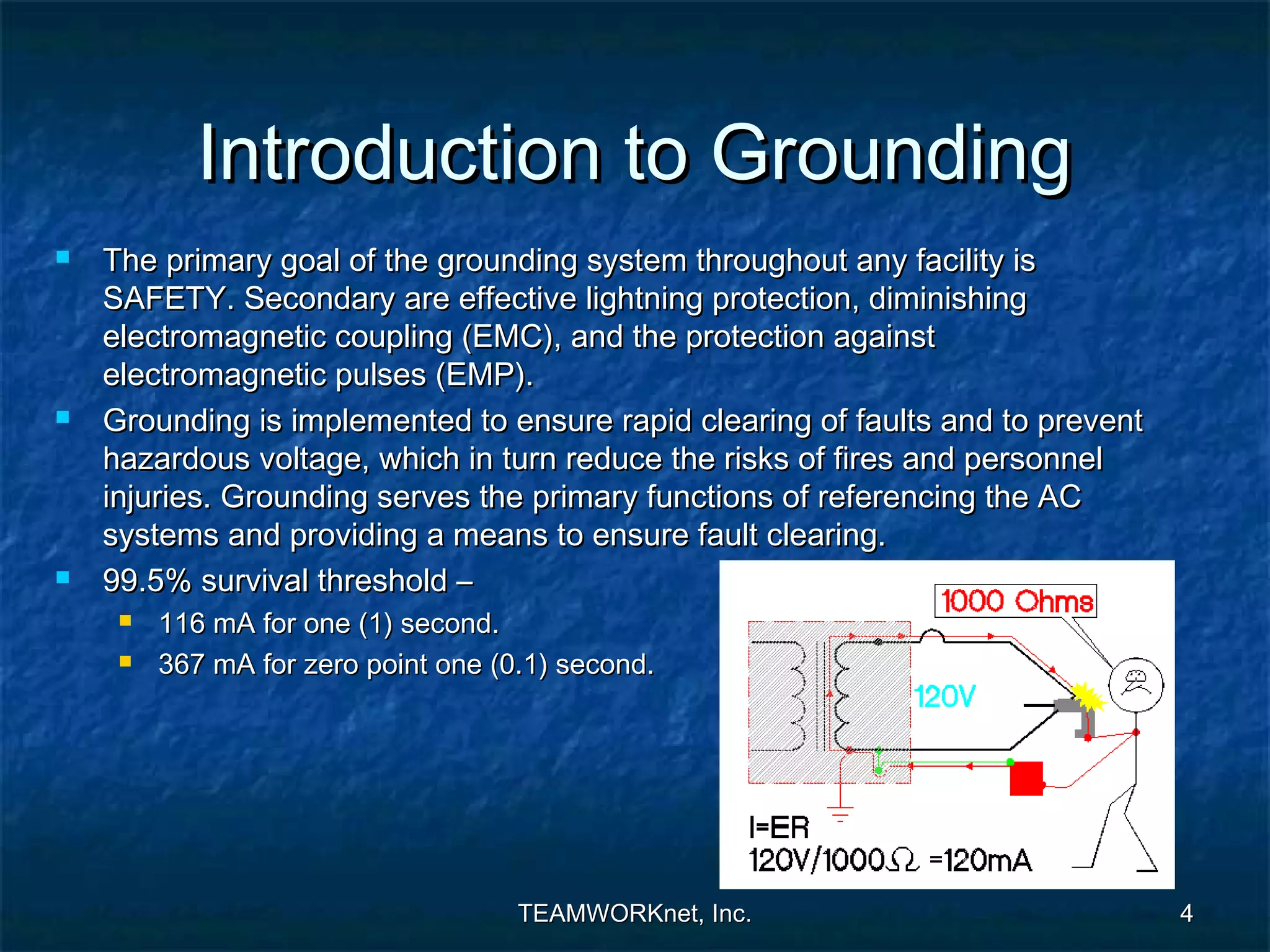
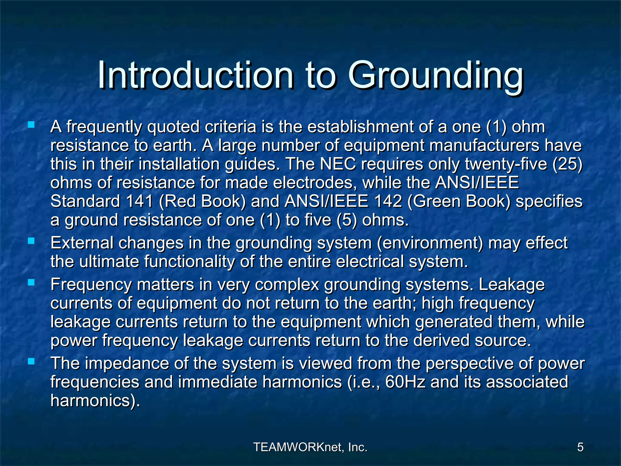
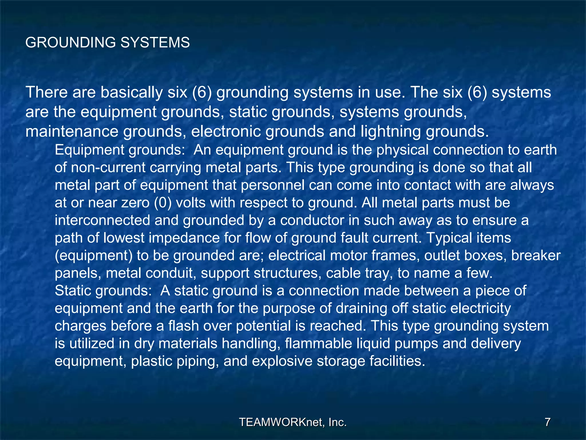
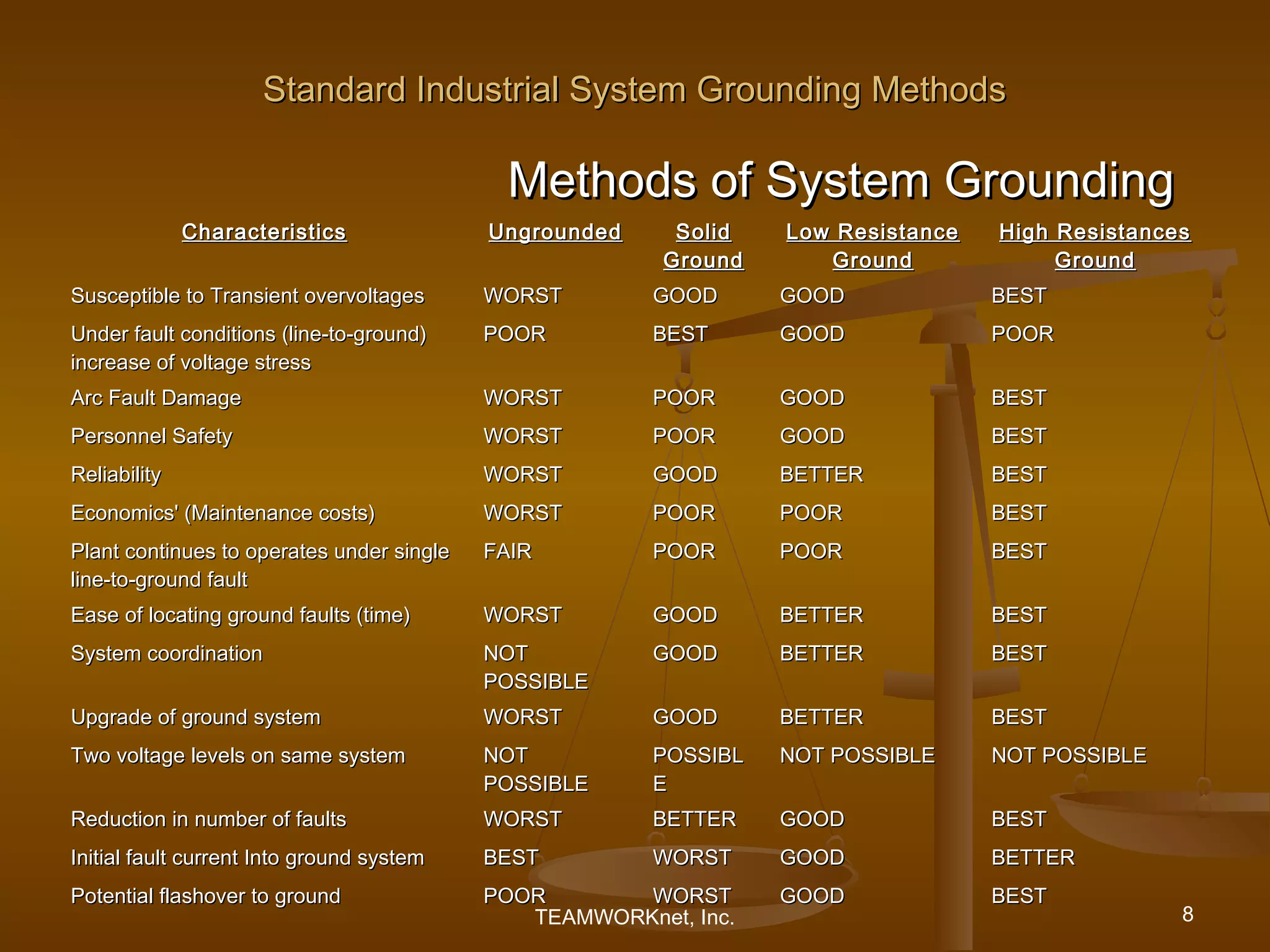
The document provides an introduction to electrical grounding practices for power systems. It discusses the primary goals of grounding for safety and protection. It also describes the different types of grounding systems used in industry, including ungrounded, solid ground, low resistance ground, and high resistance ground. Each system is characterized by its handling of faults, safety aspects, reliability and economics.
This document discusses earthing systems and the hazards of a broken neutral connection for a power transformer. It defines system earthing and equipment earthing, and explains that a broken neutral connection can cause overvoltage issues for the transformer and prevent protective relays from operating during a fault. The document also discusses the objectives and importance of proper earthing, including providing an alternative path for fault currents, ensuring safety from electric shocks, and maintaining system voltages. It provides examples of what can occur when a transformer's neutral connection to earth is broken.
ETAP - Short circuit analysis iec standardHimmelstern
The document discusses short-circuit analysis based on the IEC standard. It describes the purpose of short-circuit studies including verifying protective device ratings and settings. The types of short-circuit faults covered include three-phase, phase-to-phase, and phase-to-ground faults. The IEC method for calculating short-circuit currents is explained including initial, peak, and steady-state currents. Considerations for near-generator and far-from-generator faults are also covered.
The document discusses different types of grounding systems for electrical equipment and power systems. It defines equipment grounding as connecting the metallic enclosure of electrical equipment to earth for safety. System grounding connects parts of the power system like the neutral point to earth. The main types of system grounding discussed are ungrounded neutral, solid grounding, resistance grounding, and reactance grounding. Solid grounding directly connects the neutral to earth through a low impedance, providing effective earth potential but high fault currents. Resistance and reactance grounding limit fault currents through a resistor or reactance between neutral and earth.
Using High Resistance Grounding to Mitigate Arc Flash Hazardsmichaeljmack
Using High Resistance Grounding to Mitigate Arc Flash Hazards
Presenter: Ajit Bapat, P.E.
I-GARD's HRG systems can detect ground faults, signal alarms, and locate affected circuits to remove personnel from arc flash dangers. I-GARD's FALCON provides fast arc flash mitigation in under 1ms through adjustable light sensitivity to reduce arc flash energy. I-GARD's arc flash analysis calculates risk using IEEE and NFPA equations to develop comprehensive protection plans for a safer work environment.
The document discusses different types of grounding systems used in electrical installations. It describes six common grounding systems: equipment grounds, static grounds, system grounds, maintenance grounds, electronic grounds, and lightning grounds. It provides details on each type, including their objectives and how they are implemented. The document also discusses factors to consider when designing grounding systems and recommendations for proper grounding practices.
Earthing in a substation is important for safety. It involves connecting electrical equipment to earth at a uniform low potential to limit dangerous voltages under fault conditions. Key aspects of substation earthing design include soil resistivity testing, sizing the earth mat conductor based on fault current and duration, and ensuring step and touch potentials remain below safety limits. Proper earthing aims to provide protection to life and property against faults.
This document discusses electrical grounding and earthing systems. It begins by introducing grounding and earthing, and distinguishing between ground and neutral conductors. It then describes different types of earthing systems according to the IEC standard, including TN, TT, and IT networks. The document also covers different types of grounding used in radio communications, AC power installations, and lightning protection. It discusses the concept of virtual ground and multipoint grounding. Overall, the document provides an overview of electrical grounding and earthing systems, their uses, and important concepts.
This document discusses harmonic analysis and power quality problems caused by harmonics. It defines harmonics as voltages or currents present at integer multiples of the fundamental power system frequency. Nonlinear loads can generate harmonics. Any periodic waveform, such as a distorted voltage or current waveform, can be expressed as the sum of sinusoidal components using a Fourier series. Common harmonic sources include utilities, synchronous generators, transformers, power electronic devices, and other nonlinear loads. Harmonics can cause problems in motors, transformers, capacitors, cables, and other electrical equipment by inducing extra losses and heating. The document discusses different harmonic measurement techniques and various methods for mitigating harmonics, including passive and active filters, increasing the pulse number of converters, phase shifting
Power System Transient - Introduction.pptxssuser6453eb
This document provides an introduction to power system transients. It discusses the sources of transients, both internal like capacitor switching and external like lightning. It classifies transients into three categories based on speed: ultrafast surges, medium-fast short-circuit phenomena, and slow transient stability issues. The effects of transients are outlined, such as damage to insulation, semiconductors, and contacts. The importance of studying transients for insulation design is emphasized to prevent breakdown under overvoltage conditions.
BREAKDOWN MECHANISM OF GASEOUS , VACUUM, LIQUID & SOLID DIELECTRICSSwaminathan P
1. The document discusses breakdown mechanisms in gaseous, liquid, and solid dielectric materials. It explains that gases are good insulators at normal conditions but can break down through ionization processes under high electric fields.
2. It introduces Townsend's first ionization coefficient which describes the number of electrons produced per unit length through collisions. Cathode processes and secondary effects are also discussed.
3. Breakdown in liquid dielectrics can occur through electronic breakdown, suspended particles, cavitation, and electroconvection. Various insulating materials and their applications in different temperature classes are reviewed.
4. Insulation used in power transformers, circuit breakers, and applications of gases in power systems are summarized. Common
This document presents information on symmetrical and asymmetrical short circuit calculations. It begins by introducing the goals of appreciating Ohmic and MVA methods for symmetrical faults and symmetrical components for asymmetrical faults. It then discusses symmetrical three-phase faults which affect phases equally and can be analyzed using a single phase. Asymmetrical faults include various line-to-line and line-to-ground faults which are analyzed using symmetrical components and sequence networks. The document provides background on symmetrical components and defines positive and negative sequence components.
As the AIS (Air-Insulated Substation) is having more limitations, More and more people are going for the Gas-Insulated Substation which is environment friendly as well.
In these presentation, We discussed about theoritical and technological advancement and advantages related to GIS as compared to other substations.
We discussed different parts of the GIS as well as their operations and advantages.
By going through this presentation, you will have idea regarding comparative advantages and disadvantages of both substations.
Grounding or earthing offers two principal advantages. First, it provides protection to the power system. Secondly, earthing of electrical equipment ensures the safety of the persons handling the equipment.
- Electrical earthing provides a safe path for lightning and fault currents to protect humans and equipment.
- There are different types of earthing for different applications like LV systems, lighting, telecoms, and computers.
- Earthing can provide either Class I or Class II protection against electric shock.
- Factors that affect earth impedance include soil type and moisture, weather, electrode type and size, nearby utilities, and distance between electrodes.
- Common earthing arrangements include TN, TT, and IT systems. Measurement methods like Wenner and Schlumberger are used to determine soil resistivity which impacts earth impedance.
This document discusses the basics of earthing systems. It begins by defining important terminology related to earthing. It then discusses the disadvantages of unearthed systems and the different types of earthing including system, equipment, and reference earthing. The document outlines the basic principles and methods of system earthing, including how fault currents flow. It provides details on the earthing schemes adopted in process plants, including the voltage levels and earthing methods used. Finally, it includes an earthing conductors schedule with requirements for equipment body and instrument earthing connections.
Protection against overvoltage
overvoltage
causes of overvoltage
lightning
types of lightning strokes
harmful effect of lightning
protection against lightning
The document discusses grounding systems and their objectives which include ensuring correct operation, safety, preventing damage, dissipating lightning strokes, stabilizing voltage, and diverting stray RF energy. It then covers various aspects of grounding systems including neutral wires, ground wires, types of grounding (equipment, system, lightning/surge), grounding elements like ground rods and rod groups, soil characteristics, recommended earth resistance values for different voltage systems, substation earthing systems, step and touch potentials, resistivity measurement methods, methods to decrease ground resistance like fall of potential and Wenner's method, soil treatment alternatives, disadvantages of soil treatment, and concludes the importance of grounding and earthing systems in electrical systems.
1. The document describes a study to determine the impulse breakdown voltage of a sphere gap using an impulse voltage generator. It involves generating standard 1.2/50 μs impulse voltages using a Marx generator and measuring the breakdown voltage of a 70mm sphere gap.
2. Impulse breakdown of a sphere gap is probabilistic in nature due to the statistical time delay required for electron initiation and formation of a conductive channel. In contrast, AC breakdown always occurs at the same voltage.
3. By varying external front and tail resistances, the Marx generator controls the wave shape of the generated impulse voltages to achieve the standard 1.2/50 μs waveform.
This document discusses restricted earth fault (REF) protection schemes for transformers and generators. It explains that a REF scheme is needed to detect internal earth faults since they may not cause current to flow through the external overcurrent protection. A REF scheme works by summing the currents entering and exiting a protected zone using two sets of current transformers, and tripping if the sums are unequal, indicating an internal fault. Key elements of a REF scheme include the REF relay, stabilizing resistor to avoid spurious trips from CT mismatches, and specifying a high knee point voltage for the CTs. Examples of REF schemes for generators and transformer configurations are also provided.
Corona occurs when the voltage applied across conductors exceeds a critical disruptive voltage. This causes a faint violet glow and produces ozone, power loss, and radio interference. Corona is caused by ionization of air between conductors due to electrons gaining velocity under the influence of the electric field and colliding with air molecules. Factors that affect corona include conductor size and spacing, line voltage, and atmosphere. While corona reduces transient effects and increases conductor diameter, it also causes energy loss, ozone production, and interference. Methods to reduce corona include increasing conductor size and spacing.
So this is a power point I made. It is free for you to use as you see fit. It is to help prepare one and all for the proposed changes to the British Standard 7671 IET wiring regulations.
The content is based on the Draft for Public Comment (DPC) and all changes may not occur in the final published copy.
The presentation is in two parts, the first being the history of the IET and wiring regulations, the second being a summary (not all) of the proposed changes.
This document discusses automatic power factor correction units. It begins by explaining what power factor is and how inductive loads can cause low power factors. It then describes why power factors should be improved, such as reducing energy losses. The document outlines different methods to correct power factor, and why automatic correction is needed since loads and power factors vary. It provides details on how an automatic power factor correction unit works, including using sensors to measure voltage, current and power factor, and switching capacitors in or out to maintain a high power factor. In conclusion, automatic power factor correction can improve efficiency and minimize line losses for industrial and commercial facilities.
The document discusses various types of breakdown that can occur in solid dielectric materials. It describes intrinsic breakdown, which includes electronic and avalanche breakdown caused by electrons gaining energy from an electric field. It also discusses electromechanical breakdown that occurs when electrostatic forces exceed the material's mechanical strength. Thermal breakdown is caused by heat generated from current flow exceeding the material's ability to dissipate heat. Treeing and tracking refer to the formation of conductive pathways over time from electrical discharges partially eroding the material surface. The document provides details on the mechanisms and factors that influence different types of breakdown in solids.
Power flow through overhead transmission lines is limited by concerns over electrical phase shift, voltage drop, and thermal effects. Specifically:
- Surge impedance loading limits power flow to prevent excessive phase shift, which can cause instability. This limit depends on system voltage and transmission line characteristics.
- Voltage drop limits power flow to maintain voltage levels within 5-10% of the sending voltage. This usually limits lines 50-150 miles long.
- Thermal limits prevent overheating of conductors and maintain structural integrity. This usually determines the limit for lines under 50 miles. Longer lines are limited by phase shift or voltage drop first.
PLCC uses high voltage transmission lines to transmit speech, telemetry, and protection commands between substations in a cost effective and reliable way. Voice and data are modulated onto a carrier frequency between 40-500kHz which is injected into the power line via a coupling capacitor. Line traps are used to prevent the signal from entering substations while allowing power to pass through. The system provides an economic primary communications system for utilities over long distances without requiring separate telecommunication infrastructure.
The document presents information on earthing systems. It discusses the functions of earthing, which include providing a path for fault currents and protection from electric shock. It describes various methods of earthing, including plate earthing, pipe earthing, and rod earthing. It also discusses different types of earthing systems and applications of earthing in electrical systems. In conclusion, it emphasizes the importance of proper grounding and earthing in electrical engineering for safety and protection of electrical equipment.
The document discusses grounding and bonding in electrical installations. It explains that:
1) Grounding connections to earth limit voltage imposed by lightning or surges, while bonding connections create a low impedance path for ground fault currents.
2) Proper bonding of all metal parts together and to the service neutral is necessary for overcurrent devices to operate during ground fault conditions.
3) Both grounding and bonding work together to protect electrical systems and personnel from faults, but grounding alone does not provide protection from ground faults.
Grounding electrical systems properly protects people and equipment from faults, lightning strikes, and static discharge by providing a path to dissipate stray energy safely into the earth. Different grounding methods like single stakes, ground rods, plates, and meshes can be used depending on the site conditions and equipment. Proper testing of soil resistivity and ground resistance is important to select the suitable grounding type and ensure effectiveness of the system.
This document discusses different types of earthing systems used in electrical installations. It defines earthing as connecting electrical equipment to the earth to provide a safe path for electric current. The main purposes of earthing are to protect humans and equipment from electric shocks. The document describes maintenance free earthing and conventional earthing methods. It also explains different earthing electrodes like plates, pipes, rods and strips that are buried underground to reduce earth resistance.
The document discusses different types of grounding systems used in high voltage systems, including: equipment grounds which connect metal parts to earth to protect from electric shock; system grounds which connect one point of an electrical circuit to earth to protect equipment and aid fault detection; and solidly grounded systems where the neutral is directly connected to ground without impedance. It notes factors like voltage level, equipment type, and safety that influence grounding method selection.
Application Considerations for Power System Groundingmichaeljmack
This document discusses various grounding methods for power systems, including solid grounding, ungrounded systems, resistance grounding, and reactance grounding. It provides examples of how each method works and considerations for selecting a grounding approach based on factors like service continuity requirements and the presence of line-to-neutral loads. The document also reviews retrofitting existing systems and includes diagrams demonstrating different grounding configurations.
This document discusses different methods of grounding electrical systems, including solid grounding, resistance grounding, reactance grounding, and resonant groundings using a Peterson coil. Solid grounding directly connects the neutral point to earth, holding it at earth potential but allowing high fault currents. Resistance grounding limits fault current by connecting through a resistor. Reactance grounding uses an inductor instead of resistor. Resonant grounding with a Peterson coil adjusts the inductance to balance capacitive currents and prevent arcing faults.
The document discusses different types of earthing systems used in electrical installations. It provides details on:
- The purpose of earthing systems which is to provide protection from electric shocks and maintain safe voltages.
- Common types of earthing methods including plate, pipe, rod and strip earthing. It also discusses maintenance free earthing systems.
- Factors that determine good earthing including low resistance, corrosion resistance and ability to dissipate high fault currents.
- Causes of short circuits and how earthing provides protection during faults.
- Maximum earth resistance values that should be achieved for different electrical equipment.
This document summarizes Bangladesh's Power System Master Plan from 2010. It outlines 6 plans to achieve the vision of stable power supply by 2030: 1) Develop domestic energy resources like coal and gas. 2) Establish a diversified fuel portfolio with 50% coal, 25% gas, and 25% other sources. 3) Introduce high efficiency technologies to reduce emissions. 4) Build necessary infrastructure through multi-sector cooperation. 5) Establish efficient regulations and organizations. 6) Reduce poverty through socioeconomic growth enabled by stable power. Key recommendations include prioritizing coal plant development and domestic coal mining as well as strengthening operations and maintenance capabilities.
Impact of compression ratio on substation grounding grid resistance in layere...eSAT Journals
Abstract
This paper presents impact of grid compression ratio on substation grounding resistance. The minimization of substation grounding resistance is one of the very important criterions in design of substation grounding grid. The decrease in grid resistance reduces the ground potential rise and hence the transfer potential and to a certain extent the safety criterion touch voltage. The term compression ratio is related to unequally spaced grid. We have analyzed the grounding grid for various values of compression ratios for uniform soil model with and without vertical rods. Further the impact of compression ratio on grid resistance is analyzed for various values of soil resistivity reflection factors and top layer height in case of two layer soil model. The simulation has also been carried out for multilayer soil models using Autogrid-pro grounding software. The study results reveals that every ground grid has optimal compression ratio which makes the grid resistance minimum as compared to equally spaced grid for the same area, soil model and number of conductors. Use of ground rods, increases the compression ratio, makes the grid more uniform and decreases the grid resistance.
Keywords: compression ratio, optimal compression ratio, equally spaced grid, unequally spaced grid, ground rods, soil model.
This document outlines a 10-lecture lesson plan on electrical power systems. Lecture 1 provides an introduction and overview of power generation, transmission, and distribution. Lectures 2-4 cover basic principles including active and reactive power, the roles of different organizations, and factors like load and plant factors. Lectures 5-7 discuss economic aspects and the requirements of power systems as well as conventional sources like hydroelectric and thermal plants. Lectures 8-10 cover other generation sources such as nuclear, gas, and diesel plants. The plan provides a comprehensive overview of electrical power systems from basic concepts to various generation and economic considerations.
The electrical power system in offshore oil & gas installation, consists of a large
distribution network, generally operating in island mode i.e., without grid support. For a compact
utility plate form design, multiple gas turbine-generators without generator transformers, feed
directly to 11kV switchgear. Such a configuration however, introduces high capacitive charging
current (Ico), which is more than the preferred high resistance grounding of generator neutral
through 10A, 10sec resistor, to safeguard the generator core from damage during an earth fault.
Therefore, some utility prefers to select low resistance grounding to limit the fault current above
Ico; however this can cause severe damage to generator core. Generally, oil & gas installation is a
customized design. So, earthing scheme of 11kV generating utility system should be selected
judiciously at basic engineering stage to avoid equipment damage and protection mal-operation
during operation. Different methods of earthing scheme are available to mitigate the same. One of
the method is presented here in which generator neutral is connected to high resistance grounding
and 11kV switchgear connected to low resistance grounding though zig-zag transformer, subject to
single grounding operation at a time. Prior to synchronization or under complete load throw
scenario, generator circuit breaker is opened. So, an earth fault in generator or evacuation system,
create over-voltage or ferro-resonance conditions, stressing insulation of generator and associated
system. This is mitigated by putting neutral earthing resistor into service at generator neutral. This
paper presents the experience learned in designing neutral earthing scheme for off-shore utility
plant in view of high capacitive charging current at 11kV voltage level, outlines impact on stator
core damage, mitigation and conclusion
Why neutral grounding resisitor need continuous monitoringchidhanandhajm
This document discusses neutral grounding resistors (NGRs) and the importance of continuously monitoring them. It provides examples of problems that can occur if an NGR fails or loses connection, such as soft starter failures or transient overvoltages. Continuous monitoring can detect NGR issues and ensure ground fault protection still functions properly. An effective monitor measures resistance through the NGR to identify connectivity issues, and protects against failures that could leave systems unprotected from ground faults.
Practical Distribution & Substation Automation (Incl. Communications) for Ele...Living Online
This document provides an introduction to power system automation. It defines power system automation as a system for managing, controlling, and protecting an electrical power system using real-time information, control applications, and electrical protection. The core components of power system automation are described as local intelligence, data communications, supervisory control and monitoring. The document outlines the basic architecture of power system automation which includes the object division comprising intelligent electronic devices and remote terminal units, the communications network, and the SCADA master station which receives data and issues commands.
Telinstra provides integrated automation, electrical, and business solutions for various industrial projects. They offer control systems for facilities like tank farms, blending plants, desalination plants, and more. They also provide safety systems, process instrumentation, and centralized control rooms. Telinstra works on projects in industries such as oil and gas, manufacturing, and utilities. They handle all aspects of automation projects from design to commissioning.
The document discusses best practices for minimizing electrical noise in control panels. It covers techniques like high frequency bonding, segregating noisy components, shielding, filtering, and contact suppression. Proper grounding and bonding helps ensure all metalwork is at the same electrical potential to reduce common mode noise, while techniques like shielded cables and physical separation of components can shield noise victims from noise sources.
The document provides guidance on wiring basics for technicians, including conduit and junction box materials, wire and cable types, color and numbering conventions, termination methods, organization and protection techniques, wiring diagrams for pumps, motors, valves, and instructions for wiring on/off sensors, analog sensors, and data communication cables. Key points covered include common conduit types like PVC and EMT, using stranded copper THHN wire, adhering to color standards like green for ground and numbering wires at each end, and separating data cables from power/signal cables.
This document summarizes the key components of instrumentation cable and their purposes. It discusses the conductor, insulation, cabling elements, individual screen, assembling of cable elements, overall screen, shielding, inner sheath, armour, and outer sheath. The conductor is typically copper and can be solid or multistranded. Insulation protects individual conductors and varies based on voltage rating. Screens and sheaths protect signals and the cable internally and externally. Requirements for the outer sheath include oxygen index, acid generation, smoke density, and flammability standards.
Over-sizing of electric motors is a major cause of energy inefficiency. Motors are often sized larger than needed to drive loads, resulting in operation at partial capacity where efficiency drops significantly. Downsizing an oversized 30kW motor operating at 30% load from 75% to 85% efficiency using a 15kW motor could save 1.4kW annually, paying back the replacement cost within 6 months based on annual operating hours and local electricity rates. Proper motor sizing along with efficient motor designs and controls can achieve substantial energy savings given motors consume over half of industrial electricity usage globally.
This document provides an introduction to electrical grounding practices for power systems. It discusses the primary goals of grounding for safety and protection. It also outlines different grounding systems including equipment, static, system, maintenance, electronic and lightning grounds. The document describes various grounding methods such as ungrounded, solidly grounded, low resistance grounded and high resistance grounded systems. It discusses factors to consider for initial grounding system design such as available space, soil conditions, fault currents and code/equipment requirements.
This document provides an introduction to electrical grounding practices for power systems. It discusses the primary goals of grounding systems which are safety and effective lightning protection. It also discusses different types of grounding systems including equipment grounds, static grounds, system grounds, maintenance grounds, electronic grounds, and lightning grounds. The document outlines factors to consider in grounding system design such as soil conditions, available fault currents, NEC requirements, and lightning strike frequency. It also discusses degradation of grounding systems over time and the importance of periodic testing.
Effective Methods For Power Systems GroundingAdeen Syed
This document discusses effective methods for power system grounding. It begins by explaining the two primary reasons for grounding are protection/safety and reference voltage. There are various types of grounding systems classified based on whether the system is ungrounded, grounded through neutral grounding, or grounded through non-neutral grounding. Neutral grounding can be done through solid grounding, voltage transformer grounding, zig-zag transformer grounding, or resistance/reactance grounding. The document analyzes the advantages and disadvantages of different grounding methods and concludes grounding is important for both reliability and stability of power systems.
This document discusses various methods of neutral grounding systems for electrical power systems, including their advantages and disadvantages. It describes ungrounded systems, solidly grounded systems, and various resistance grounded systems such as low resistance, high resistance, and resonant grounding. Resistance grounding limits fault currents to reduce equipment damage while still allowing faults to be detected. High resistance grounding further limits currents to below 10 amps, requiring a detection system since faults will not trip breakers. Resonant grounding uses inductive reactance to cancel out the capacitive fault current. Earthing transformers provide an alternative return path for faults on delta windings.
SYSTEM NEUTRAL EARTHING
-DEFINITION OF SYSTEM EARTHING
-Comparative Performance For Various Conditions Using Different Earthing Methods
-EQUIPMENT SIZING
- APPENDIX FOR TYPICAL EARTHING TRANSFORMER SIZING
- APPENDIX GIVING GUIDELINE FOR SIZING OF COMMON BUS CONNECTED MEDIUM RESISTANCE EARTHING
This document discusses different types of neutral grounding systems for power systems, including their advantages and disadvantages. It covers ungrounded systems, solidly grounded systems, low resistance grounded systems, and high resistance grounded systems. High resistance grounding limits fault current to 5 amps or less, which controls transient overvoltage, reduces equipment damage and safety hazards, and allows continued system operation after a ground fault is detected.
This document discusses different types of neutral grounding systems for power systems, including their advantages and disadvantages. It covers ungrounded systems, solidly grounded systems, low resistance grounded systems, and high resistance grounded systems. High resistance grounding limits fault current to a low value, which reduces hazards to personnel and equipment damage. It allows continued system operation after a ground fault occurs and helps control transient overvoltages.
Post Glover is a leading manufacturer of grounding solutions and dynamic braking resistors. They have over 130 years of combined industrial and utility experience. Their factory in Kentucky integrates computer-aided design and manufacturing with strong engineering capabilities. Their experienced sales and engineering team provides timely support and response. Post Glover designs and manufactures products in accordance with all applicable safety standards. They offer various grounding solutions including neutral grounding resistors and grounding transformers.
Multi – Grounding in the Distribution System.pptxMarlonAgustin3
The document discusses grounding and fault clearing in distribution systems. It defines grounding as connecting electrical systems and equipment to earth. Distribution system grounding is important for fault detection and clearing to limit outages. Systems use multiple grounding points along the neutral to keep voltage rises low during faults. Faults can be phase-to-ground or phase-to-phase and are cleared using fuses, reclosers, and substation circuit breakers in a coordinated manner to isolate damage while attempting to save downstream protective devices.
There are five main types of high voltage grounding systems: ungrounded, solidly grounded, resistance grounded, resonant grounded, and high resistance grounded. Resistance grounding limits fault currents to prevent equipment damage while still allowing faults to be detected. It works by connecting a grounding resistor between the neutral and ground to limit fault current to a safe level according to Ohm's law. This prevents damage but ensures protective devices can still operate to clear faults.
The document discusses different methods of earthing or grounding electrical systems. It defines earthing as connecting electrical equipment to earth through a low resistance wire to provide an alternative path for fault currents. The key methods discussed are:
- Solid or effective grounding, which directly connects the neutral to earth. This allows large fault currents but limits equipment costs.
- Resistance grounding, which connects the neutral to earth through a resistor. This limits fault currents but increases equipment costs.
- Reactance grounding uses an inductor instead of resistor to limit fault currents.
- Peterson coil grounding cancels out capacitive fault currents through resonant tuning of an inductor.
This presentation, given by Georgia Power, discusses the importance of grounding and bonding. Real life examples are given and how they were handled as well as safety measures.
PROTECTION AGAINST OVER VOLTAGE AND GROUNDING Part 2Dr. Rohit Babu
- The document discusses grounded and ungrounded neutral systems in power systems.
- In an ungrounded system, the neutral is isolated from ground which can cause overvoltages and issues with fault detection.
- Grounded systems connect the neutral to ground to limit voltages and improve safety, reliability and fault detection.
- Common methods for grounding the neutral include solid grounding, resistance grounding, reactance grounding and Peterson coil grounding. The selection depends on system size and protection requirements.
PROTECTION AGAINST OVER VOLTAGE AND GROUNDINGDr. Rohit Babu
- The document discusses grounded and ungrounded neutral systems in power systems.
- In an ungrounded system, the neutral is isolated from ground which can cause overvoltages and issues with fault detection.
- Grounded systems connect the neutral to ground to limit voltages and improve safety, reliability and fault detection.
- Common methods for grounding the neutral include solid grounding, resistance grounding, reactance grounding and Peterson coil grounding. The selection depends on system size and protection requirements.
Successful operation of entire power system depends to a considerable extent on efficient and satisfactory performance of substations. Hence substations in general can be considered as heart of overall power system. In any substation, a well-designed grounding plays an important role. Since absence of safe and effective grounding system can result in mal-operation or non-operation of control and protective devices, grounding system design deserves considerable attention for all the substations. There are two primary functions of a safe earthing system. Firstly, ensure that a person who is in the vicinity of earthed facilities during a fault is not exposed to the possibility of a fatal electrical shock. Secondly, provide a low impedance path to earth for currents occurring under normal and fault conditions.The earthing conductors, composing the grid and connections to all equipment and structures, must possess sufficient thermal capacity to pass the highest fault current for the required time
Grounding in Power System Presentation
The presentation discusses the importance of grounding in power systems for safety, equipment protection, and building protection from lightning strikes. It covers types of grounding including solid grounding, resistance grounding, reactance grounding, and resonant grounding. Measurement instruments and calculation procedures for proper grounding are also reviewed. Lack of proper grounding can cause electric shocks, fires, and equipment damage. IEEE standards provide guidelines for industrial and commercial grounding systems.
This document discusses various grounding techniques for electrical systems. It begins by comparing different grounding methods such as ungrounded, solidly grounded, and resistance grounded systems. It then focuses on high resistance grounding and describes how HRG limits fault currents while allowing systems to continue operating after ground faults. The document provides examples of applying HRG to generators, variable frequency drives, and paralleled power sources. It discusses component ratings, fault currents, harmonics, and coordination of protection devices for HRG systems.
Your electrical safety specilist for all equipments Powered AC and DCMahesh Chandra Manav
We all are aware that we are applying lots of Artficial Sources to make our Life Comforts .
For This we are installing Many Electrical Equipments Power AC & DC and Electric Vehicles Inside our Building and out Side and in this process many of metal Part is entering into our Building.
To ensure better perform and Human Safety Earthing of Equipment and Conductive stucture is very important Value from 1 Ohms up to 0.25 Ohms.
Our National Building Code 2016 is alreday given Guide Line and Supporting by MBBL2019
(Manual Building By LAW).
Internal Switch and External Lightning will very Danger for our Equipments and Human Lives May Cause Assest Damage up to Sacrifice Human Live due to Fire and Electric Change.
We have to Design and protect our Building or Permises form External Lightning by Nature use NBC IS/IEC 62305.
When Lightning Fall any Condutive Like Pole ,Transmission Line and React with Ground may be Shift 100kA Fault Current into our Building use Surge Protection Device to product from any ind of Direct and Indirect Threat.
JMV LPS Ltd belive Make in India Noida Base Company Manufacturer Design ,Engineering ,Supply and Installation.
Maintenance Free Earthing ,Copper Clad Steet Sof Conductore, Exothermic Weld, External Lightning Protection and per IS/IEC62305, Surge Protection Devive as per IS/IEC 62035.
Your electrical safety specilist for all equipments Powered AC and DC
Good grounding practices
1. GOOD GROUNDING
PRACTICES
A Brief Introduction to the Basics
of Electrical Grounding for Power
Systems
TEAMWORKnet, Inc.
6550 New Tampa Highway By:
Suite B
Lakeland, Florida 33815 Harry J. Tittel, E.E.
(863) 327-1080
Vice President TEAMWORKnet, Inc.
(863) 327-1091 fax
2. Provides Complete Spectrum of
Electrical Engineering Services
Provides Electrical Testing Services
and Thermal Imaging Surveys
Complete Provider of AutoCAD or
Microstation V8 Services, including
Scanning, Printing and Archiving
Process Control Specialists
TEAMWORKnet, Inc. 2
3. Introduction to Grounding
TABLE OF CONTENTS
1.0 Introduction to Grounding
2.0 Standard Industrial Grounding Methods and Types of Grounding
3.0 Grounding System and Design Considerations
4.0 Open Question and Answer Session
TEAMWORKnet, Inc. 3
4. Introduction to Grounding
The primary goal of the grounding system throughout any facility is
SAFETY. Secondary are effective lightning protection, diminishing
electromagnetic coupling (EMC), and the protection against
electromagnetic pulses (EMP).
Grounding is implemented to ensure rapid clearing of faults and to prevent
hazardous voltage, which in turn reduce the risks of fires and personnel
injuries. Grounding serves the primary functions of referencing the AC
systems and providing a means to ensure fault clearing.
99.5% survival threshold –
116 mA for one (1) second.
367 mA for zero point one (0.1) second.
TEAMWORKnet, Inc. 4
5. Introduction to Grounding
A frequently quoted criteria is the establishment of a one (1) ohm
resistance to earth. A large number of equipment manufacturers have
this in their installation guides. The NEC requires only twenty-five (25)
ohms of resistance for made electrodes, while the ANSI/IEEE
Standard 141 (Red Book) and ANSI/IEEE 142 (Green Book) specifies
a ground resistance of one (1) to five (5) ohms.
External changes in the grounding system (environment) may effect
the ultimate functionality of the entire electrical system.
Frequency matters in very complex grounding systems. Leakage
currents of equipment do not return to the earth; high frequency
leakage currents return to the equipment which generated them, while
power frequency leakage currents return to the derived source.
The impedance of the system is viewed from the perspective of power
frequencies and immediate harmonics (i.e., 60Hz and its associated
harmonics).
TEAMWORKnet, Inc. 5
6. Introduction to Grounding
Generally accepted electrical wiring practices are not good ground
system wiring practices (i.e. no sharp bends or turns).
Grounding systems are not meant to last for ever. The best grounding
systems need to most attention paid to them as they will corrode the
quickest.
TEAMWORKnet, Inc. 6
7. GROUNDING SYSTEMS
There are basically six (6) grounding systems in use. The six (6) systems
are the equipment grounds, static grounds, systems grounds,
maintenance grounds, electronic grounds and lightning grounds.
Equipment grounds: An equipment ground is the physical connection to earth
of non-current carrying metal parts. This type grounding is done so that all
metal part of equipment that personnel can come into contact with are always
at or near zero (0) volts with respect to ground. All metal parts must be
interconnected and grounded by a conductor in such away as to ensure a
path of lowest impedance for flow of ground fault current. Typical items
(equipment) to be grounded are; electrical motor frames, outlet boxes, breaker
panels, metal conduit, support structures, cable tray, to name a few.
Static grounds: A static ground is a connection made between a piece of
equipment and the earth for the purpose of draining off static electricity
charges before a flash over potential is reached. This type grounding system
is utilized in dry materials handling, flammable liquid pumps and delivery
equipment, plastic piping, and explosive storage facilities.
TEAMWORKnet, Inc. 7
8. Standard Industrial System Grounding Methods
Methods of System Grounding
Characteristics Ungrounded Solid Low Resistance High Resistances
Ground Ground Ground
Susceptible to Transient overvoltages WORST GOOD GOOD BEST
Under fault conditions (line-to-ground) POOR BEST GOOD POOR
increase of voltage stress
Arc Fault Damage WORST POOR GOOD BEST
Personnel Safety WORST POOR GOOD BEST
Reliability WORST GOOD BETTER BEST
Economics' (Maintenance costs) WORST POOR POOR BEST
Plant continues to operates under single FAIR POOR POOR BEST
line-to-ground fault
Ease of locating ground faults (time) WORST GOOD BETTER BEST
System coordination NOT GOOD BETTER BEST
POSSIBLE
Upgrade of ground system WORST GOOD BETTER BEST
Two voltage levels on same system NOT POSSIBL NOT POSSIBLE NOT POSSIBLE
POSSIBLE E
Reduction in number of faults WORST BETTER GOOD BEST
Initial fault current Into ground system BEST WORST GOOD BETTER
Potential flashover to ground POOR WORST GOOD BEST
TEAMWORKnet, Inc. 8
9. TYPES OF GROUNDING SYSTEMS
Ungrounded System:
The ungrounded system is one that has no intentional connection
between the neutral or any phase and ground. Please note that an
ungrounded system is grounded through the concept of
capacitively coupling. The neutral potential of an ungrounded
system, with balanced loading will be close to ground potential due
to the capacitance between each phase conductor and ground.
Low ground fault current.
Very high voltages to ground potential on unfaulted phases.
Sustained faults lead to system line-to-line voltages on unfaulted
line.
Insulation failure.
Failure due to restrike ground faults.
Continued operation of facility.
TEAMWORKnet, Inc. 9
10. TYPES OF GROUNDING SYSTEMS
Solidly Grounded System:
The solidly grounded system is one that has the neutral connected
to ground without an intentional impedance. In contrast to the
ungrounded system the solidly grounded system will result in a
large magnitude of current to flow (Aids in coordination), but has
no increase in voltage on unfaulted phases.
Low initial cost to install and implement, but stray currents then
become a possible consequence.
Common in low voltage distribution systems, such as overhead
lines.
typically feeds to transformer primary with high side fuse protection.
Not the preferred grounding scheme for industrial or commercial
facilities due to high magnitude fault currents.
TEAMWORKnet, Inc. 10
11. TYPES OF GROUNDING SYSTEMS
Low Resistance Grounded System:
The low resistance grounded system is one that has the neutral
connected to ground through a small resistance that limits the
fault current. The size of the grounding resistor is selected to
detect and clear the faulted circuit..
The resistor can limit ground currents to a desired level based on
coordination requirement or relay limitations.
Limits transient overvoltages during ground faults.
Low resistance grounding is not recommended for low voltage
systems due to the limited ground fault current. This reduced fault
current can be insufficient to positively operate fuses and/or series
trip units.
Ground fault current typically in the 100 – 600 Amp range.
TEAMWORKnet, Inc. 11
12. TYPES OF GROUNDING SYSTEMS
High Resistance Grounded System:
The high resistance grounded system is one that has the neutral
connected to ground through a resistive impedance whose resistance is
selected to allow a ground fault current through the resistor equal to or
slightly more that the capacitive charging current of the system.
The resistor can limit ground currents to a desired level based on
coordination requirement or relay limitations.
Limits transient overvoltages during ground faults.
Physically large resistor banks.
Very low ground fault current, typically under 10 Amps.
Special relaying methods utilized to detect and remove ground faults.
High resistance grounding is typically applied to situations where it is
essential to prevent unplanned outages.
Recent trend has been to utilize high resistance grounding methods on 600
volt systems and lower.
TEAMWORKnet, Inc. 12
13. GROUNDING SYSTEMS
System grounds: A system ground refers to the point in an electrical circuit
that is connected to earth. This connection point is typically at the electrical
neutral. The sole purpose of the system ground is to protect equipment.
This type ground also provides a low impedance path for fault currents
improving ground fault coordination. This ensures longer insulation life of
motors, transformers and other system components.
Maintenance grounds: This type ground is utilized for safe work practices,
and is a temporary ground.
Electronic and computer grounds: Grounding for electronic equipment is a
special case in which the equipment ground and the system ground are
combined and applied in unity. Electronic equipment grounding systems
must not only provide a means of stabilizing input voltage levels, but also
act as the zero (0) voltage reference point. Grounding systems for the
modern electronics installation must be able to provide effective grounding
and bonding functions well into the high frequency megahertz range.
Lightning protection: Lightning protection grounding requirements are
dependent upon the structure, equipment to be protected, and the level of
lightning protection required of desired.
TEAMWORKnet, Inc. 13
14. GROUNDING SYSTEMS
► Several factures should be considered in the initial design of the
grounding system.
The area available for installation of the grounding system. This could lead
to the requirement and utilization of chemical rods, or wells.
Water table and seasonal changes to it.
Soil condition and resistivity, Please see chart of typical results. Also
elevation above sea level and hard rocky soil are concerns that would need
to be addressed.
Available fault currents (i.e., three (3) phase, line-to-ground, and line-to-
line-to ground, etc.).
NEC and ANSI/IEEE requirements. Also include here the requirements of
the process equipment to be installed.
Consideration to the number of lightning strikes and thunder storm days
per year.
Utility ties and/or service entrance voltage levels.
Utilization of area were ground system is to be installed, (i.e., do not install
under paved parking lot).
TEAMWORKnet, Inc. 14
15. GROUNDING SYSTEMS
SOIL RESISTIVITIES
(Approximate Ohm-Meters)
Description1,2 Median Min. Max.
Topsoil's, loams 26 1 50
Inorganic clays of high plasticity 33 10 55
Fills-ashes, cinders, brine wastes 38 6 70
Silty or clayey fine sands with slight plasticity 55 30 80
Porous limestone, chalk 65 30 100
Clayey sands, poorly graded sand-clay mixtures 125 50 200
Fine sandy or silty clays, silty clays, lean clays 140 80 200
Clay-sand-gravel mixtures 145 40 250
Marls 3
155 10 300
Decomposed granites, gneisses4, etc. 300 100 500
Clayey gravel, poorly graded gravel 300 200 400
Silty sands, poorly graded sand-silt mixtures 300 100 500
Sands, sandstone 510 20 1,000
Gravel, gravel-sand mixtures 800 600 1,000
Slates, schists5, gneiss, igneous rocks, shales, granites, basalts 1,500 1,000 2,000
Quartzite's, crystalline limestone, marble, crystalline rocks 5,500 1,000 10,000
Notes: 1. Low resistivity soils are highly influenced by the presence of moisture.
2. Low resistivity soils are more corrosive than high resistivity soils.
3. Crumbly soil composed mostly of clay with a high limestone content.
4. Metamorphic rock formed by recrystallization of granite, separated into bands.
5. Metamorphic rock much coarser than gneiss.
This chart compiled from data published in:
IEEE Standard 142-1991, Recommended Grounding Practices
British Standard Code of Practice, CP-1013: 1965, Earthing
Megger: A Simple Guide to Earth Testing
Biddle: Getting Down to Earth
TEAMWORKnet, Inc. 15
16. GROUNDING SYSTEMS
1. Parity sized grounding conductors.
2. Grounding symmetry in all parallel feeders.
3. Zones of equipment with localized transformers to
isolate the equipment and control leakage current.
4. Limiting the quantity of devices grounded by any
single conductor.
5. Utilizing specialty transformers to limit ground
interference.
6. Faraday cage design concepts.
7. Use different networks throughout the facility as
opposed to a single ended data network.
8. Reference grids in all computer, data processing
and information technology rooms.
9. Perimeter ground ring bonded to the service
entrance.
10. Intentional continuity of structural steel.
11. Bonding of all communication cables to structural
steel.
12. Architectural steel treatment for lightning
protection.
13. Ufer ground treatment per NEC for all main vertical
steel footers.
14. Grounding grid below moisture barrier.
15. Bonding horizontal steel pans to structural steel.
TEAMWORKnet, Inc. 16
17. GROUNDING SYSTEMS
► Several factures can degrade initially good grounding systems. These
factors indicate the importance of continuous periodic testing (Typically
once per calendar year unless problems arise). A change (lower) in the
water table across the USA would lead to a degrade in the grounding
system. Another consideration in the ground system would be in facility
growth and the addition of non-metallic piping and conduit which do not
provide low resistance ground connections. Along with the these
concerns are the increase load and associated increase in available
fault currents. The better the ground system, the more attention should
be paid to corroded electrodes. All these could result in the need for a
decrease in the grounding resistance.
Testing: Periodic testing should be done to assure grounding system
effectiveness.
TEAMWORKnet, Inc. 17
22. Florida Electrical Resources Earth Ground Test Report
A Division of TEAMWORKnet, Inc. Project : 302xxxx Test Page 1
Earth Ground Test Data Analysis & Problem Classification
Engineer Bill Engel, P.E. & Harry Tittel, E.E. Test Method Clamp on Ground Tester
Client / Facility Client Name Photograph No. 0
Amperage Reading 0 mA
Location Saw Mill Area Test Results 46.2 Ω
Notes: Ground Tested High. Perform
Date January 8, 2001 Maintenance on Ground or
Time 9:30 AM Replace.
Ambient Conditions 83 °F, Humid, Dry Ground
Test Point Digital Image Test Point Location Representation
GROUND
CABLE
Saw Mill
FLORIDA ELECTRICAL RESOURCES 6550 New Tampa Hwy., Suite B Lakeland, Florida 33815 (800) 727-4337 (863) 327-1080 Fax (863) 327-1091
A Division of TEAMWORKnet, Inc.
TEAMWORKnet, Inc. 22
23. Florida Electrical Resources Earth Ground Test Report
A Division of TEAMWORKnet, Inc. Project : 302xxxx Test Page 2
Earth Ground Test Data Analysis & Problem Classification
Engineer Harry Tittel, E.E. Test Method Clamp on Ground Tester
Client / Facility Client Name Photograph No. 7
Amperage Reading 34 mA
Location Stacker, Sorter, C-N-S Area Test Results 1.5 Ω
Debarker Area Notes: Ground Tested Within
Date January 8, 2001 Parameters.
Time 11:35 AM
Ambient Conditions 93 °F, Humid, Dry Ground
Test Point Digital Image Test Point Location Representation
GROUND
Debarker
Log Deck
Stacker
Oil Sorter
C-N-S
FLORIDA ELECTRICAL RESOURCES 6550 New Tampa Hwy., Suite B Lakeland, Florida 33815 (800) 727-4337 (863) 327-1080 Fax (863) 327-1091
A Division of TEAMWORKnet, Inc.
TEAMWORKnet, Inc. 23