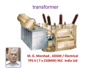
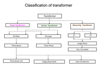
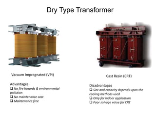
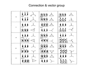
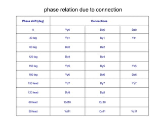
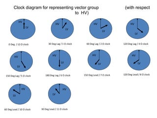
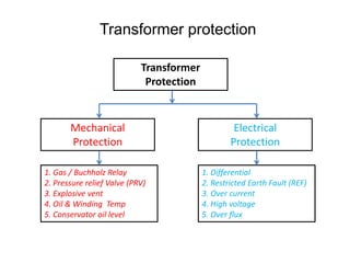
1. The document discusses different types of transformers used in power plants including power transformers, service transformers, and measuring transformers.
2. It describes key components of transformers like the core, windings, cooling systems, and protections devices. Transformer connections, vector groups, and voltage classifications are also covered.
3. Various transformers used in thermal power plants are discussed including generator transformers, station transformers, unit auxiliary transformers, and those used for distribution within the plant.
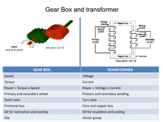
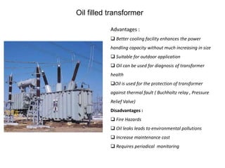
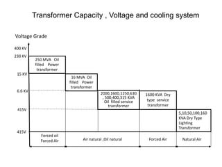
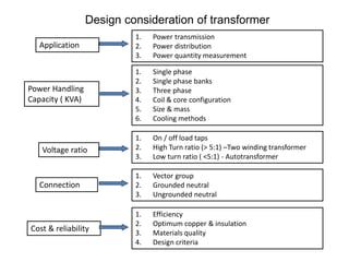
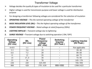
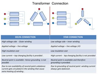
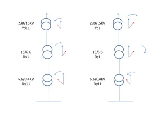
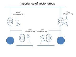
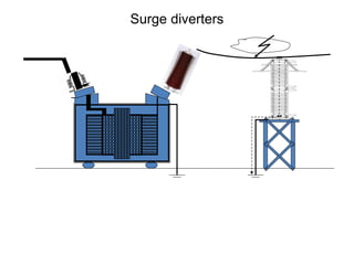
Test done on Power transformers.
Insulation Resistance test, Winding Resistance test, Ratio Measurements, Magnetic balance test, Tan delta test, DIssolved gas analysis for transformer, Sweep frequency response analysis.
Testing and Condition Monitoring of Substation EquipmentsSumeet Ratnawat
Testing and condition monitoring of substation equipments,Transformer specifications,Monitoring of Transformer,On-load Tap changer,Overhauling,Tan delta and capacitance,Thermal imaging,Sweep frequency response analysis,Oil analysis of Switchgear elements containing oil,tests on insulating oil,Breaker monitoring,Condition monitoring of CT,Condition monitoring of CVT,Surge Arresters,Condition monitoring of relays.
How is power transformer protected??? This provides a basic understanding of power transformer. Furthermore, the protective relay application on power transformer is included.
On Load Tap Changer (OLTC) is used in "High Power Transformers" to control output voltage, when electric load on transformers get increase the output voltage get decrease due to internal voltage drop inside winding, change in tap is required to maintain output voltage. OLTC is a device which perform tap changing in High Power Transformers during On Load conditions and is powered by a motor.
This ppt describes the function of Power Transformer in a Power Generation plant. Here DPL(Durgapur Projects Limited) was our VT venue, so chose it as the Base.
WHAT IS TRANSFORMER, DEFINE TRANSFORMER, TYPES OF TRANSFORMER, RATINGS OF TRANSFORMERS, MANUFACTURING PROCESS OF TRANSFORMER, PARTS OF TRANSFORMER, TESTS OF TRANSFORMER, COSTING OF COPPER.
Distribution Transformer Manufacturing at Navana Electronics ltd (Aliv)Md Abu Jauad Khan Aliv
This Presentation I covered at my final year (Aug, 2014) of my BSc in EEE at IUBAT. Worked as an Intern at Navana Electronics Limited for 3 months at manufacturing division and I came up with this idea.
Construction of Transformers with materials and its advantages, Working
Principle of Transformers, Core Type and Shell Type Transformers with its
applications, EMF Equation of Transformers,
Application of Transformer.
Single Phase Auto Transformer, Volt-ampere Relations, Step-up Auto
transformers,
Parallel operation of Transformers
with reasons and necessary conditions
Saudi Arabia stands as a titan in the global energy landscape, renowned for its abundant oil and gas resources. It's the largest exporter of petroleum and holds some of the world's most significant reserves. Let's delve into the top 10 oil and gas projects shaping Saudi Arabia's energy future in 2024.
Hybrid optimization of pumped hydro system and solar- Engr. Abdul-Azeez.pdffxintegritypublishin
Advancements in technology unveil a myriad of electrical and electronic breakthroughs geared towards efficiently harnessing limited resources to meet human energy demands. The optimization of hybrid solar PV panels and pumped hydro energy supply systems plays a pivotal role in utilizing natural resources effectively. This initiative not only benefits humanity but also fosters environmental sustainability. The study investigated the design optimization of these hybrid systems, focusing on understanding solar radiation patterns, identifying geographical influences on solar radiation, formulating a mathematical model for system optimization, and determining the optimal configuration of PV panels and pumped hydro storage. Through a comparative analysis approach and eight weeks of data collection, the study addressed key research questions related to solar radiation patterns and optimal system design. The findings highlighted regions with heightened solar radiation levels, showcasing substantial potential for power generation and emphasizing the system's efficiency. Optimizing system design significantly boosted power generation, promoted renewable energy utilization, and enhanced energy storage capacity. The study underscored the benefits of optimizing hybrid solar PV panels and pumped hydro energy supply systems for sustainable energy usage. Optimizing the design of solar PV panels and pumped hydro energy supply systems as examined across diverse climatic conditions in a developing country, not only enhances power generation but also improves the integration of renewable energy sources and boosts energy storage capacities, particularly beneficial for less economically prosperous regions. Additionally, the study provides valuable insights for advancing energy research in economically viable areas. Recommendations included conducting site-specific assessments, utilizing advanced modeling tools, implementing regular maintenance protocols, and enhancing communication among system components.
Overview of the fundamental roles in Hydropower generation and the components involved in wider Electrical Engineering.
This paper presents the design and construction of hydroelectric dams from the hydrologist’s survey of the valley before construction, all aspects and involved disciplines, fluid dynamics, structural engineering, generation and mains frequency regulation to the very transmission of power through the network in the United Kingdom.
Author: Robbie Edward Sayers
Collaborators and co editors: Charlie Sims and Connor Healey.
(C) 2024 Robbie E. Sayers
Final project report on grocery store management system..pdfKamal Acharya
In today’s fast-changing business environment, it’s extremely important to be able to respond to client needs in the most effective and timely manner. If your customers wish to see your business online and have instant access to your products or services.
Online Grocery Store is an e-commerce website, which retails various grocery products. This project allows viewing various products available enables registered users to purchase desired products instantly using Paytm, UPI payment processor (Instant Pay) and also can place order by using Cash on Delivery (Pay Later) option. This project provides an easy access to Administrators and Managers to view orders placed using Pay Later and Instant Pay options.
In order to develop an e-commerce website, a number of Technologies must be studied and understood. These include multi-tiered architecture, server and client-side scripting techniques, implementation technologies, programming language (such as PHP, HTML, CSS, JavaScript) and MySQL relational databases. This is a project with the objective to develop a basic website where a consumer is provided with a shopping cart website and also to know about the technologies used to develop such a website.
This document will discuss each of the underlying technologies to create and implement an e- commerce website.
Cosmetic shop management system project report.pdfKamal Acharya
Buying new cosmetic products is difficult. It can even be scary for those who have sensitive skin and are prone to skin trouble. The information needed to alleviate this problem is on the back of each product, but it's thought to interpret those ingredient lists unless you have a background in chemistry.
Instead of buying and hoping for the best, we can use data science to help us predict which products may be good fits for us. It includes various function programs to do the above mentioned tasks.
Data file handling has been effectively used in the program.
The automated cosmetic shop management system should deal with the automation of general workflow and administration process of the shop. The main processes of the system focus on customer's request where the system is able to search the most appropriate products and deliver it to the customers. It should help the employees to quickly identify the list of cosmetic product that have reached the minimum quantity and also keep a track of expired date for each cosmetic product. It should help the employees to find the rack number in which the product is placed.It is also Faster and more efficient way.
Water scarcity is the lack of fresh water resources to meet the standard water demand. There are two type of water scarcity. One is physical. The other is economic water scarcity.
2. Gear Box and transformer
Input
Torque & speed
GB ratio= n1/ n2
Turn ratio= n1/ n2
GEAR BOX TRANSFORMER
Speed Voltage
Torque Current
Power = Torque x Speed Power = Voltage x Current
Primary and secondary wheel Primary and secondary winding
Teeth ratio Turn ratio
Frictional loss Core and copper loss
Oil for lubrication and cooling Oil for insulation and cooling
Slip Vector group
3. Classification of transformer
Transformer
Power Transformer Service Transformer Measuring Transformer
Dry type
Auto transformer
Three Phase
Oil filled CT PT
Single Phase
Dry / oil cooled
Three phase
Three phase unit Single phase bank
4. Oil filled transformer
Advantages :
Better cooling facility enhances the power
handling capacity without much increasing in size
Suitable for outdoor application
Oil can be used for diagnosis of transformer
health
Oil is used for the protection of transformer
against thermal fault ( Buchholtz relay , Pressure
Relief Valve)
Disadvantages :
Fire Hazards
Oil leaks leads to environmental pollutions
Increase maintenance cost
Requires periodical monitoring
5. Dry Type Transformer
Vacuum Impregnated (VPI) Cast Resin (CRT)
Advantages
No fire hazards & environmental
pollution
No maintenance cost
Maintenance free
Disadvantages
Size and capacity depends upon the
cooling methods used
Only for indoor application
Poor salvage value for CRT
6. Purpose of Transformer in thermal power plant
1. To step up the voltage for long distance transmission of
electric power with high voltage & low current ( GT)
2. To interconnect two grid of different system voltage (ICT)
3. To step down the voltage for providing supply source to load
capacity >175KW through 6.6 KV HT bus (UAT)
4. To step down the voltage for providing supply source to load
capacity <175KW through 415 V KV LT bus (UST)
5. Providing supply source nearest to the load centre to avoid
voltage buckling during start of load.
7. Transformer arrangement in TPSII
GT(15/230KV)
ST(230/6.6KV)
ICT
(400/230KV)
Ex Tr 15KV/600V)
UAT B
15/6.6KV
BR 63MVAR
UAT B
15/6.6KV
ESP Tr A 6.6KV/415V
ESP Tr B 6.6KV/415V
UST A 6.6KV/415V
UST A 6.6KV/415V
6.6/11KV
Ring main system
SST 6.6KV/415V
LHS 6.6KV/415V
ADPH 6.6KV/415V
ESP
HVR
ESP
HVR
8. Transformer Capacity , Voltage and cooling system
5,10,50,100,160
KVA Dry Type
Lighting
Transformer
2000,1600,1250,630
, 500,400,315 KVA
Oil filled service
transformer
16 MVA Oil
filled Power
transformer
415V
415V
6.6 KV
250 MVA Oil
filled Power
transformer
15 KV
400 KV
230 KV
1600 KVA Dry
type service
transformer
Forced oil
Forced Air Air natural ,Oil natural Forced Air Natural Air
Voltage Grade
9. TRANSFORMER CAPACITY : VA / KVA /MVA
Load 1
Load 2
Load 3
Load 4
Load current (A)
LoadVoltage(V)
Capacity (VA) : √3 x V x A
Standard Transformer capacity in KVA as per IS 2026 :
5, 6.3, 8, 10, 12.5,16,20,25,31.5, 40,50,63,80,
100,125,160,200,250,315,400,500,630,800,1000
10. Design consideration of transformer
Application
Power Handling
Capacity ( KVA)
Voltage ratio
1. Single phase
2. Single phase banks
3. Three phase
4. Coil & core configuration
5. Size & mass
6. Cooling methods
1. Power transmission
2. Power distribution
3. Power quantity measurement
1. On / off load taps
2. High Turn ratio (> 5:1) –Two winding transformer
3. Low turn ratio ( <5:1) - Autotransformer
Connection
1. Vector group
2. Grounded neutral
3. Ungrounded neutral
Cost & reliability
1. Efficiency
2. Optimum copper & insulation
3. Materials quality
4. Design criteria
11.
12.
13.
14. Voltage decides the quality & types of insulation to be used for a particular transformer.
Higher voltage is used for transmission purpose and lower voltage is used for distribution
purpose
For designing a transformer following voltages are considered for the selection of insulation
1. OPERATING VOLTAGE – This the nominal operating voltage of the transformer
2. BASIC INSULATION LEVEL (BIL) – This the highest operating voltage of the transformer.
3. POWER FREQUENCY VOLTAGE - Rated voltage at rated frequency (50Hz)
4. LIGHTING IMPULSE – Transient voltage due to lightening
5. SURGE VOLTAGE – Transient voltage due to switching operation ( ON / OFF)
Operating
Voltage
(KV rms)
BIL
(KV rms)
Power
frequency
voltage
(KV rms)
Switching
Impulse
(KV Peak )
Lighting impulse
(KV Peak )
0.433 1.1 3 - Not applicable
3.3 3.6 10 - 20- 40
6.6 7.2 20 - 40- 60
11 12 28 - 60- 75
15 17..5 38 - 75- 95
33 36 70 - 145- 170
230 245 325-395 - 750- 950
400 420 570 - 630 950-1050 1300-1425
Transformer Voltage
15. Tap changer in Transformer to change the secondary voltage
Two types of tap changer –
1 On Load Tap Changer (OLTC ) - HV side
2. Off Circuit Tap changer (OCTC) – Secondary side
16. Transformer Connection
DELTA CONNECTION STAR CONNECTION
High voltage side - Outer winding Low voltage side – Inner winding
Applied voltage – line voltage Applied voltage – line voltage /√3
High insulation cost Low insulation cost
Low current – tap changing facility is provided . High current - tap changing facility is not provided
Neutral point is available –hence grounding is not
possible
Neutral point is available and therefore
grounding is provided.
Due to non availability of neutral point unbalance
current gets circulated in the winding that cause
extra heating of winding .
Due to grounding of neutral point winding current
always gets balanced .
17. Three phase wave form
Primary applied
voltage & current
wave form
Secondary
induced voltage
& current wave
form
19. Phase shift (deg) Connections
0 Yy0 Dd0 Dz0
30 lag Yd1 Dy1 Yz1
60 lag Dd2 Dz2
120 lag Dd4 Dz4
150 lag Yd5 Dy5 Yz5
180 lag Yy6 Dd6 Dz6
150 lead Yd7 Dy7 Yz7
120 lead Dd8 Dz8
60 lead Dd10 Dz10
30 lead Yd11 Dy11 Yz11
phase relation due to connection
20. LV
HV
0 Deg / 12 O clock
LV
HV
30 Deg Lag / 1 O clock
LV
HV
60 Deg Lag / 2 O clock
LV
HV
150 Deg Lag / 5 O clock
LV
HV
180 Deg Lag / 6 O clock
LV
HV
150 Deg Lead / 7 O clock
LV
HV
120 Deg Lead / 8 O clock
LV
HV
60 Deg Lead / 10 O clock
LV
HV
30 Deg Lead / 11 O clock
LV
HV
120 Deg Lag / 4 O clock
Clock diagram for representing vector group (with respect
to HV)
22. YNd11
LV lead by 30 Deg
Dyn1
LV lag by 30 Deg
YNd1
LV lag by 30 Deg
Dyn1
LV lag by 30 Deg
Importance of vector group
23. Application of transformers in thermal power
plant
1. Transmission of power : (Power Transformer) –
a. Generator Transformer (GT), 250 MVA
b. Interconnecting transformer (ICT)
c. Unit Auxiliary Transformer (UAT)
d. Station Transformer(ST)
2. Distribution of power : ( service Transformer) –
a. Unit Service transformer
b. Station Service transformers
c. Unit Auxiliary Transformer (UAT)
d. Station Transformer(ST)
2. Direct Loading Transformer
a. Lighting Transformer
b. ESP Rectifier Transformer
24. Functions of GT,ST & ICTs
400 KV National Grid
ICT
ICT
ST
State
generating
station Central
generating
station
HV DC Line
HV DC Line
31. Pressure relief valve ( PRV)
1. It is mounted on the top of the
transformer
2. Relieves pressure impulses due to
massive internal fault conditions.
3. Helps to prevent the tank from
bursting or splitting by tripping
transformer
4. Operates within 10-15 ms
1. The spring are held in compression by
the cover and press on a disc which seals
an opening in the tank top.
2. If the pressure in the tank exceeds the
operating pressure (more than 3 Ksc) ,
the disk move upwards and release
pressure.
3. After pressure decreases spring recloses
the disk and thereby avoid loss of oil.
33. Ambient Temp
(50 Deg C)
Temp Rise
(55 Deg C)
Hot spot
Temp
(10 Deg C)
Ambient Temp
(50 Deg C)
Temp Rise
(45 Deg C)
Hot spot
Temp
(10 Deg C)
Alarm :
105 Deg C
Trip :
115 Deg C
Alarm :
95 Deg C
Trip :
105 Deg C
Winding Temp Oil Temp
Average operating
temp : 60 to 75 Deg C
Fan starts : 55 Deg C
Fan stops : 50 Deg C
Pump starts : 65 Deg C
Pump stops : 60 Deg C
35. R Y B IDMT
Relay
CT
Over current relay (IDMT Type)
Inverse Define Minimum Time (IDMT)
Time
Fault Current
36. 64 RGT
51NGT Stand by E/F
F2
E/F Current
F1
CT core 4
500 / 4A
GT
15.75 / 400KV
Restricted Earth Fault and Stand by Earth
fault
37. Protection against high voltage
Over voltages can be caused by
Lightning over voltages due to Lightning strokes ,
Switching over voltages due to switching and circuit breaking
Temporary over voltages due to power frequency overvoltage or
Temporary over voltages due to acing ground as an effect of line to earth fault in an
isolated neutral system.