Download as PDF, PPTX


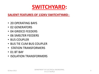
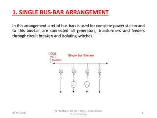


The document is a seminar report on switchyard equipment and protection systems at NTPC-SAIL Power Company Private Limited in Rourkela, India. It provides an overview of the captive power plant, including its major equipment like generators, transformers, and switchyard components. The switchyard contains 20 operating bays including generators, grid feeders, smelter feeders, and transformers. Important switchyard components discussed include busbars, bus couplers, insulators, circuit breakers, isolators, current and voltage transformers, and lightning arresters.


