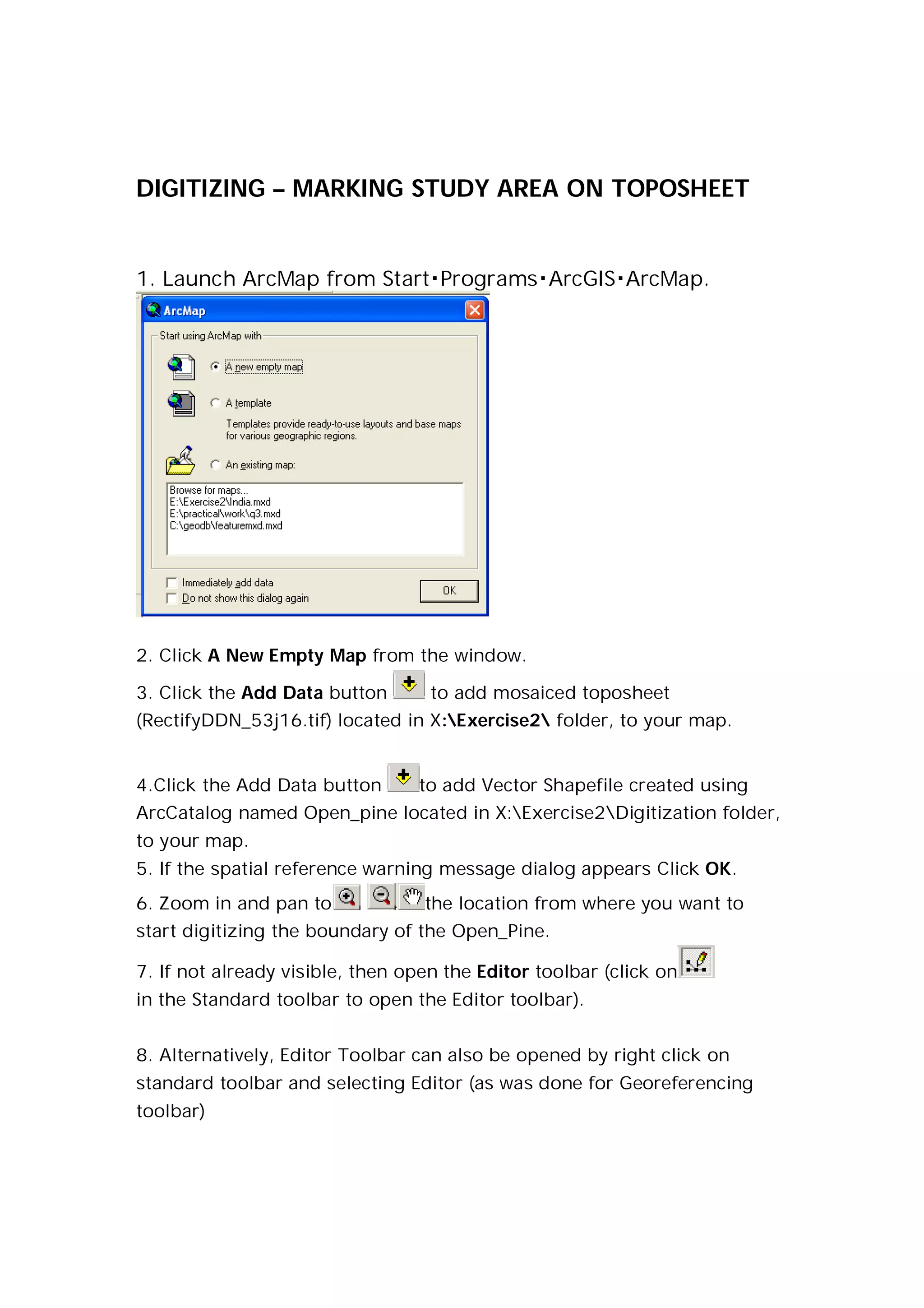
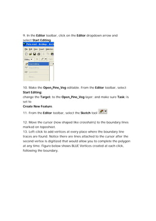
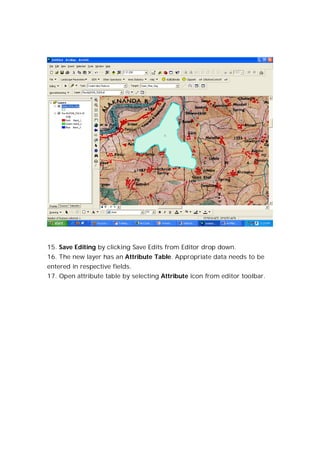
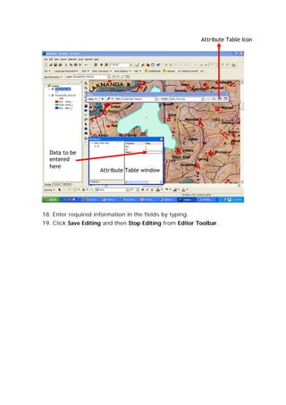
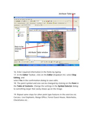
DIGITIZING – MARKING STUDY AREA ON TOPOSHEET


1. Launch ArcMap from StartProgramsArcGISArcMap.


2. Click A New Empty Map from the window.

3. Click the Add Data button       to add mosaiced toposheet
(RectifyDDN_53j16.tif) located in X:Exercise2 folder, to your map.


4.Click the Add Data button      to add Vector Shapefile created using
ArcCatalog named Open_pine located in X:Exercise2Digitization folder,
to your map.
5. If the spatial reference warning message dialog appears Click OK.
6. Zoom in and pan to             the location from where you want to
start digitizing the boundary of the Open_Pine.

7. If not already visible, then open the Editor toolbar (click on
in the Standard toolbar to open the Editor toolbar).


8. Alternatively, Editor Toolbar can also be opened by right click on
standard toolbar and selecting Editor (as was done for Georeferencing
toolbar)
9. In the Editor toolbar, click on the Editor dropdown arrow and
select Start Editing.


10. Make the Open_Pine_Veg editable. From the Editor toolbar, select
Start Editing;
change the Target: to the Open_Pine_Veg layer; and make sure Task: is
set to
Create New Feature.

11. From the Editor toolbar, select the Sketch tool


12. Move the cursor (now shaped like crosshairs) to the boundary lines
marked on toposheet.
13. Left-click to add vertices at every place where the boundary line
traces are found. Notice there are lines attached to the cursor after the
second vertex is digitized that would allow you to complete the polygon
at any time. Figure below shows BLUE Vertices created at each click,
following the boundary.
14. To finish digitizing the polygon, just double-click with the left mouse
button to close it (i.e., the second-to-last point or when you get close to
where you placed the first vertex). Your new polygon should look
something like this:
15. Save Editing by clicking Save Edits from Editor drop down.
16. The new layer has an Attribute Table. Appropriate data needs to be
entered in respective fields.
17. Open attribute table by selecting Attribute icon from editor toolbar.
Attribute Table Icon


  Data to be
  entered
  here
                     Attribute Table window


18. Enter required information in the fields by typing.
19. Click Save Editing and then Stop Editing from Editor Toolbar.
DIGITIZING OTHER FEATURES (POINT TYPE)

1. Click the Add Data button       to add Vector Shapefile created using
ArcCatalog named Village located in X:Exercise2Digitizatopn folder, to
your map.


2. If the spatial reference warning message dialog appears Click OK.

3. If not already visible, then open the Editor toolbar (click on     in the
Standard toolbar to open the Editor toolbar).


4.Alternatively, Editor Toolbar can also be opened by right click
on standard toolbar and selecting Editor.


5. In the Editor toolbar, click on the Editor dropdown arrow and
select Start Editing.


6. All of the features of the Editor toolbar are now available. Use
the Target: dropdown list to select Village as the target layer.
(Edits are saved in the layer indicated in the Target Box.)


7. In the Editor toolbar, use the Task: dropdown list to select Create New
Feature.
8.Use the dropdown list to select (click on) the Sketch Tool


9. Zoom in and pan                  to the location from where you want to
start digitizing the Village as a point.
10. Move the cursor (now shaped like crosshairs) over the center of one
of the identified village. Click once with the cursor.


11. Repeat for several other Village Feature.
12. Notice: Since the Feature Class for the Shapefile has been set to point,
only point features are created.


13. Save Editing by clicking Save Edits from Editor drop down.


14. The new layer has an Attribute Table. Appropriate data needs to be
entered in respective fields.

15. Open attribute table by selecting Attribute icon from editor toolbar.
Attribute Table Icon


 Data to be
 entered
 here
                 Attribute Table window


16. Enter required information in the fields by typing.
17. In the Editor Toolbar, click on the Editor dropdown list, select Stop
Editing, and
select Yes in the confirmation dialog to save edits.
18. The point symbol and size can be changed by clicking on the Point in
the Table of Contents. Change the settings in the Symbol Selector dialog
to something larger that easily shows up on the image.


19. Repeat same steps for other point type features in the exercise viz.
Carcass. Live Elephants, Range Office, Forest Guest House, Waterholes,
CheckGates etc…
DIGITIZING OTHER FEATURES (LINE TYPE)

1. Click the Add Data button       to add Vector Shapefile created using
ArcCatalog named River_Alakananda located in X:Exercise2Digitizatopn
folder, to your map.


2. If the spatial reference warning message dialog appears Click OK.

3. If not already visible, then open the Editor toolbar (click on     in the
Standard toolbar to open the Editor toolbar).


4.Alternatively, Editor Toolbar can also be opened by right click
on standard toolbar and selecting Editor.


5. In the Editor toolbar, click on the Editor dropdown arrow and
select Start Editing.


6. All of the features of the Editor toolbar are now available. Use
the Target: dropdown list to select Village as the target layer.
(Edits are saved in the layer indicated in the Target Box.)


7. In the Editor toolbar, use the Task: dropdown list to select Create New
Feature.
8.Use the dropdown list to select (click on) the Sketch Tool


9. Zoom in and pan                  to the location from where you want to
start digitizing the Village as a point.
10. Move the cursor (now shaped like crosshairs) over the center of one
of the identified village. Click once with the cursor.


11. Repeat for several other Features.
12. Notice: Since the Feature Class for the Shapefile has been set to point,
only point features are created.


13. Save Editing by clicking Save Edits from Editor drop down.


14. The new layer has an Attribute Table. Appropriate data needs to be
entered in respective fields.


15. Open attribute table by selecting Attribute icon from editor toolbar.
Attribute Table Icon


                                                                                 Data to be
                                                                                 entered here


                                                  Attribute Table Edit
                                                  window


16. Enter required information in the fields by typing.
17. In the Editor Toolbar, click on the Editor dropdown list, select Stop
Editing, and select Yes in the confirmation dialog to save edits.
18. The point symbol and size can be changed by clicking on the Point in
the Table of Contents. Change the settings in the Symbol Selector dialog
to something larger that easily shows up on the image.


19. Repeat same steps for other point type features in the exercise viz.
Carcass. Roads,railway lines

Digitization arc gis

  • 1.
    DIGITIZING – MARKINGSTUDY AREA ON TOPOSHEET 1. Launch ArcMap from StartProgramsArcGISArcMap. 2. Click A New Empty Map from the window. 3. Click the Add Data button to add mosaiced toposheet (RectifyDDN_53j16.tif) located in X:Exercise2 folder, to your map. 4.Click the Add Data button to add Vector Shapefile created using ArcCatalog named Open_pine located in X:Exercise2Digitization folder, to your map. 5. If the spatial reference warning message dialog appears Click OK. 6. Zoom in and pan to the location from where you want to start digitizing the boundary of the Open_Pine. 7. If not already visible, then open the Editor toolbar (click on in the Standard toolbar to open the Editor toolbar). 8. Alternatively, Editor Toolbar can also be opened by right click on standard toolbar and selecting Editor (as was done for Georeferencing toolbar)
  • 2.
    9. In theEditor toolbar, click on the Editor dropdown arrow and select Start Editing. 10. Make the Open_Pine_Veg editable. From the Editor toolbar, select Start Editing; change the Target: to the Open_Pine_Veg layer; and make sure Task: is set to Create New Feature. 11. From the Editor toolbar, select the Sketch tool 12. Move the cursor (now shaped like crosshairs) to the boundary lines marked on toposheet. 13. Left-click to add vertices at every place where the boundary line traces are found. Notice there are lines attached to the cursor after the second vertex is digitized that would allow you to complete the polygon at any time. Figure below shows BLUE Vertices created at each click, following the boundary.
  • 3.
    14. To finishdigitizing the polygon, just double-click with the left mouse button to close it (i.e., the second-to-last point or when you get close to where you placed the first vertex). Your new polygon should look something like this:
  • 4.
    15. Save Editingby clicking Save Edits from Editor drop down. 16. The new layer has an Attribute Table. Appropriate data needs to be entered in respective fields. 17. Open attribute table by selecting Attribute icon from editor toolbar.
  • 5.
    Attribute Table Icon Data to be entered here Attribute Table window 18. Enter required information in the fields by typing. 19. Click Save Editing and then Stop Editing from Editor Toolbar.
  • 6.
    DIGITIZING OTHER FEATURES(POINT TYPE) 1. Click the Add Data button to add Vector Shapefile created using ArcCatalog named Village located in X:Exercise2Digitizatopn folder, to your map. 2. If the spatial reference warning message dialog appears Click OK. 3. If not already visible, then open the Editor toolbar (click on in the Standard toolbar to open the Editor toolbar). 4.Alternatively, Editor Toolbar can also be opened by right click on standard toolbar and selecting Editor. 5. In the Editor toolbar, click on the Editor dropdown arrow and select Start Editing. 6. All of the features of the Editor toolbar are now available. Use the Target: dropdown list to select Village as the target layer. (Edits are saved in the layer indicated in the Target Box.) 7. In the Editor toolbar, use the Task: dropdown list to select Create New Feature.
  • 7.
    8.Use the dropdownlist to select (click on) the Sketch Tool 9. Zoom in and pan to the location from where you want to start digitizing the Village as a point. 10. Move the cursor (now shaped like crosshairs) over the center of one of the identified village. Click once with the cursor. 11. Repeat for several other Village Feature. 12. Notice: Since the Feature Class for the Shapefile has been set to point, only point features are created. 13. Save Editing by clicking Save Edits from Editor drop down. 14. The new layer has an Attribute Table. Appropriate data needs to be entered in respective fields. 15. Open attribute table by selecting Attribute icon from editor toolbar.
  • 8.
    Attribute Table Icon Data to be entered here Attribute Table window 16. Enter required information in the fields by typing. 17. In the Editor Toolbar, click on the Editor dropdown list, select Stop Editing, and select Yes in the confirmation dialog to save edits. 18. The point symbol and size can be changed by clicking on the Point in the Table of Contents. Change the settings in the Symbol Selector dialog to something larger that easily shows up on the image. 19. Repeat same steps for other point type features in the exercise viz. Carcass. Live Elephants, Range Office, Forest Guest House, Waterholes, CheckGates etc…
  • 9.
    DIGITIZING OTHER FEATURES(LINE TYPE) 1. Click the Add Data button to add Vector Shapefile created using ArcCatalog named River_Alakananda located in X:Exercise2Digitizatopn folder, to your map. 2. If the spatial reference warning message dialog appears Click OK. 3. If not already visible, then open the Editor toolbar (click on in the Standard toolbar to open the Editor toolbar). 4.Alternatively, Editor Toolbar can also be opened by right click on standard toolbar and selecting Editor. 5. In the Editor toolbar, click on the Editor dropdown arrow and select Start Editing. 6. All of the features of the Editor toolbar are now available. Use the Target: dropdown list to select Village as the target layer. (Edits are saved in the layer indicated in the Target Box.) 7. In the Editor toolbar, use the Task: dropdown list to select Create New Feature.
  • 10.
    8.Use the dropdownlist to select (click on) the Sketch Tool 9. Zoom in and pan to the location from where you want to start digitizing the Village as a point. 10. Move the cursor (now shaped like crosshairs) over the center of one of the identified village. Click once with the cursor. 11. Repeat for several other Features. 12. Notice: Since the Feature Class for the Shapefile has been set to point, only point features are created. 13. Save Editing by clicking Save Edits from Editor drop down. 14. The new layer has an Attribute Table. Appropriate data needs to be entered in respective fields. 15. Open attribute table by selecting Attribute icon from editor toolbar.
  • 11.
    Attribute Table Icon Data to be entered here Attribute Table Edit window 16. Enter required information in the fields by typing. 17. In the Editor Toolbar, click on the Editor dropdown list, select Stop Editing, and select Yes in the confirmation dialog to save edits. 18. The point symbol and size can be changed by clicking on the Point in the Table of Contents. Change the settings in the Symbol Selector dialog to something larger that easily shows up on the image. 19. Repeat same steps for other point type features in the exercise viz. Carcass. Roads,railway lines