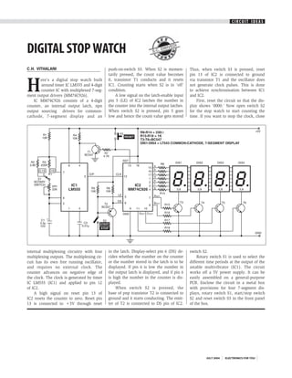
CIRCUIT IDEAS


DIGITAL STOP WATCH                                                      S.C.
                                                                             DWI
                                                                                VED
                                                                                   I


C.H. VITHALANI                                push-on-switch S3. When S2 is momen-            Thus, when switch S3 is pressed, reset
                                              tarily pressed, the count value becomes         pin 13 of IC2 is connected to ground


H
       ere’s a digital stop watch built       0, transistor T1 conducts and it resets         via transistor T1 and the oscillator does
        around timer IC LM555 and 4-digit     IC1. Counting starts when S2 is in ‘off’        not generate clock pulses. This is done
        counter IC with multiplexed 7-seg-    condition.                                      to achieve synchronisation between IC1
ment output drivers (MM74C926).                    A low signal on the latch-enable input     and IC2.
   IC MM74C926 consists of a 4-digit          pin 5 (LE) of IC2 latches the number in             First, reset the circuit so that the dis-
counter, an internal output latch, npn        the counter into the internal output latches.   play shows ‘0000.’ Now open switch S2
output sourcing drivers for common-           When switch S2 is pressed, pin 5 goes           for the stop watch to start counting the
cathode, 7-segment display and an             low and hence the count value gets stored       time. If you want to stop the clock, close


internal multiplexing circuitry with four     in the latch. Display-select pin 6 (DS) de-     switch S2.
multiplexing outputs. The multiplexing cir-   cides whether the number on the counter             Rotary switch S1 is used to select the
cuit has its own free running oscillator,     or the number stored in the latch is to be      different time periods at the output of the
and requires no external clock. The           displayed. If pin 6 is low the number in        astable multivibrator (IC1). The circuit
counter advances on negative edge of          the output latch is displayed, and if pin 6     works off a 5V power supply. It can be
the clock. The clock is generated by timer    is high the number in the counter is dis-       easily assembled on a general-purpose
IC LM555 (IC1) and applied to pin 12          played.                                         PCB. Enclose the circuit in a metal box
of IC2.                                           When switch S2 is pressed, the              with provisions for four 7-segment dis-
    A high signal on reset pin 13 of          base of pnp transistor T2 is connected to       plays, rotary switch S1, start/stop switch
IC2 resets the counter to zero. Reset pin     ground and it starts conducting. The emit-      S2 and reset switch S3 in the front panel
13 is connected to +5V through reset          ter of T2 is connected to DS pin of IC2.        of the box.


                                                                                                        JULY 2004   ELECTRONICS FOR YOU

Digital stop watch

  • 1.
    CIRCUIT IDEAS DIGITAL STOPWATCH S.C. DWI VED I C.H. VITHALANI push-on-switch S3. When S2 is momen- Thus, when switch S3 is pressed, reset tarily pressed, the count value becomes pin 13 of IC2 is connected to ground H ere’s a digital stop watch built 0, transistor T1 conducts and it resets via transistor T1 and the oscillator does around timer IC LM555 and 4-digit IC1. Counting starts when S2 is in ‘off’ not generate clock pulses. This is done counter IC with multiplexed 7-seg- condition. to achieve synchronisation between IC1 ment output drivers (MM74C926). A low signal on the latch-enable input and IC2. IC MM74C926 consists of a 4-digit pin 5 (LE) of IC2 latches the number in First, reset the circuit so that the dis- counter, an internal output latch, npn the counter into the internal output latches. play shows ‘0000.’ Now open switch S2 output sourcing drivers for common- When switch S2 is pressed, pin 5 goes for the stop watch to start counting the cathode, 7-segment display and an low and hence the count value gets stored time. If you want to stop the clock, close internal multiplexing circuitry with four in the latch. Display-select pin 6 (DS) de- switch S2. multiplexing outputs. The multiplexing cir- cides whether the number on the counter Rotary switch S1 is used to select the cuit has its own free running oscillator, or the number stored in the latch is to be different time periods at the output of the and requires no external clock. The displayed. If pin 6 is low the number in astable multivibrator (IC1). The circuit counter advances on negative edge of the output latch is displayed, and if pin 6 works off a 5V power supply. It can be the clock. The clock is generated by timer is high the number in the counter is dis- easily assembled on a general-purpose IC LM555 (IC1) and applied to pin 12 played. PCB. Enclose the circuit in a metal box of IC2. When switch S2 is pressed, the with provisions for four 7-segment dis- A high signal on reset pin 13 of base of pnp transistor T2 is connected to plays, rotary switch S1, start/stop switch IC2 resets the counter to zero. Reset pin ground and it starts conducting. The emit- S2 and reset switch S3 in the front panel 13 is connected to +5V through reset ter of T2 is connected to DS pin of IC2. of the box. JULY 2004 ELECTRONICS FOR YOU