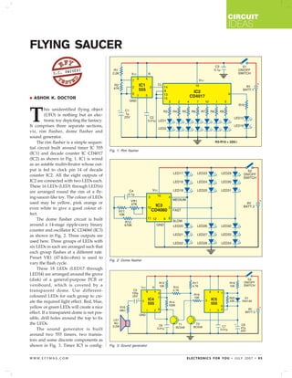
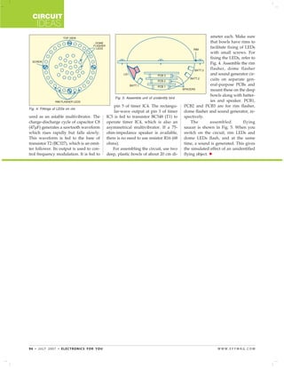
CIRCUIT
                                                                                          IDEAS

FLYING SAUCER

                    IVEDI
             S.C. DW


  ASHOK K. DOCTOR


T
         his unidentified flying object
         (UFO) is nothing but an elec-
         tronic toy depicting the fantacy.
It comprises three separate sections,
viz, rim flasher, dome flasher and
sound generator.
    The rim flasher is a simple sequen-
tial circuit built around timer IC 555
                                             Fig. 1: Rim flasher
(IC1) and decade counter IC CD4017
(IC2) as shown in Fig. 1. IC1 is wired
as an astable multivibrator whose out-
put is fed to clock pin 14 of decade
counter IC2. All the eight outputs of
IC2 are connected with two LEDs each.
These 16 LEDs (LED1 through LED16)
are arranged round the rim of a fly-
ing-saucer-like toy. The colour of LEDs
used may be yellow, pink orange or
even white to give a good colour ef-
fect.
    The dome flasher circuit is built
around a 14-stage ripple-carry binary
counter and oscillator IC CD4060 (IC3)
as shown in Fig. 2. Three outputs are
used here. Three groups of LEDs with
six LEDs in each are arranged such that
each group flashes at a different rate.
Preset VR1 (47-kilo-ohm) is used to
                                             Fig. 2: Dome flasher
vary the flash cycle.
    These 18 LEDs (LED17 through
LED34) are arranged around the grove
(disk) of a general-purpose PCB or
veroboard, which is covered by a
transparent dome. Use different-
coloured LEDs for each group to cre-
ate the required light effect. Red, blue,
yellow or green LEDs will create a nice
effect. If a transparent dome is not pos-
sible, drill holes around the top to fix
the LEDs.
    The sound generator is built
around two 555 timers, two transis-
tors and some discrete components as
shown in Fig. 3. Timer IC5 is config-        Fig. 3: Sound generator


WWW.EFYMAG.COM                                                         ELECTRONICS FOR YOU • JULY 2007 • 95
CIRCUIT
     IDEAS
                                                                                                         ameter each. Make sure
                                                                                                         that bowls have rims to
                                                                                                         facilitate fixing of LEDs
                                                                                                         with small screws. For
                                                                                                         fixing the LEDs, refer to
                                                                                                         Fig. 4. Assemble the rim
                                                                                                         flasher, dome flasher
                                                                                                         and sound generator cir-
                                                                                                         cuits on separate gen-
                                                                                                         eral-purpose PCBs and
                                                                                                         mount these on the deep
                                                                                                         bowls along with batter-
                                               Fig. 5: Assemble unit of unidentify bird
                                                                                                         ies and speaker. PCB1,
                                               pin 5 of timer IC4. The rectangu-          PCB2 and PCB3 are for rim flasher,
Fig. 4: Fittings of LEDs on rim
                                               lar-wave output at pin 3 of timer          dome flasher and sound generator, re-
ured as an astable multivibrator. The      IC5 is fed to transistor BC548 (T1) to         spectively.
charge-discharge cycle of capacitor C8     operate timer IC4, which is also an                The        assembled           flying
(47µF) generates a sawtooth waveform       asymmetrical multivibrator. If a 75-           saucer is shown in Fig. 5. When you
which rises rapidly but falls slowly.      ohm-impedance speaker is available,            switch on the circuit, rim LEDs and
This waveform is fed to the base of        there is no need to use resistor R16 (68       dome LEDs flash, and at the same
transistor T2 (BC327), which is an emit-   ohms).                                         time, a sound is generated. This gives
ter follower. Its output is used to con-      For assembling the circuit, use two         the simulated effect of an unidentified
trol frequency modulation. It is fed to    deep, plastic bowls of about 20 cm di-         flying object.


96 • JULY 2007 • ELECTRONICS FOR YOU                                                                         WWW.EFYMAG.COM

Flying saucer

  • 1.
    CIRCUIT IDEAS FLYING SAUCER IVEDI S.C. DW ASHOK K. DOCTOR T his unidentified flying object (UFO) is nothing but an elec- tronic toy depicting the fantacy. It comprises three separate sections, viz, rim flasher, dome flasher and sound generator. The rim flasher is a simple sequen- tial circuit built around timer IC 555 Fig. 1: Rim flasher (IC1) and decade counter IC CD4017 (IC2) as shown in Fig. 1. IC1 is wired as an astable multivibrator whose out- put is fed to clock pin 14 of decade counter IC2. All the eight outputs of IC2 are connected with two LEDs each. These 16 LEDs (LED1 through LED16) are arranged round the rim of a fly- ing-saucer-like toy. The colour of LEDs used may be yellow, pink orange or even white to give a good colour ef- fect. The dome flasher circuit is built around a 14-stage ripple-carry binary counter and oscillator IC CD4060 (IC3) as shown in Fig. 2. Three outputs are used here. Three groups of LEDs with six LEDs in each are arranged such that each group flashes at a different rate. Preset VR1 (47-kilo-ohm) is used to Fig. 2: Dome flasher vary the flash cycle. These 18 LEDs (LED17 through LED34) are arranged around the grove (disk) of a general-purpose PCB or veroboard, which is covered by a transparent dome. Use different- coloured LEDs for each group to cre- ate the required light effect. Red, blue, yellow or green LEDs will create a nice effect. If a transparent dome is not pos- sible, drill holes around the top to fix the LEDs. The sound generator is built around two 555 timers, two transis- tors and some discrete components as shown in Fig. 3. Timer IC5 is config- Fig. 3: Sound generator WWW.EFYMAG.COM ELECTRONICS FOR YOU • JULY 2007 • 95
  • 2.
    CIRCUIT IDEAS ameter each. Make sure that bowls have rims to facilitate fixing of LEDs with small screws. For fixing the LEDs, refer to Fig. 4. Assemble the rim flasher, dome flasher and sound generator cir- cuits on separate gen- eral-purpose PCBs and mount these on the deep bowls along with batter- Fig. 5: Assemble unit of unidentify bird ies and speaker. PCB1, pin 5 of timer IC4. The rectangu- PCB2 and PCB3 are for rim flasher, Fig. 4: Fittings of LEDs on rim lar-wave output at pin 3 of timer dome flasher and sound generator, re- ured as an astable multivibrator. The IC5 is fed to transistor BC548 (T1) to spectively. charge-discharge cycle of capacitor C8 operate timer IC4, which is also an The assembled flying (47µF) generates a sawtooth waveform asymmetrical multivibrator. If a 75- saucer is shown in Fig. 5. When you which rises rapidly but falls slowly. ohm-impedance speaker is available, switch on the circuit, rim LEDs and This waveform is fed to the base of there is no need to use resistor R16 (68 dome LEDs flash, and at the same transistor T2 (BC327), which is an emit- ohms). time, a sound is generated. This gives ter follower. Its output is used to con- For assembling the circuit, use two the simulated effect of an unidentified trol frequency modulation. It is fed to deep, plastic bowls of about 20 cm di- flying object. 96 • JULY 2007 • ELECTRONICS FOR YOU WWW.EFYMAG.COM