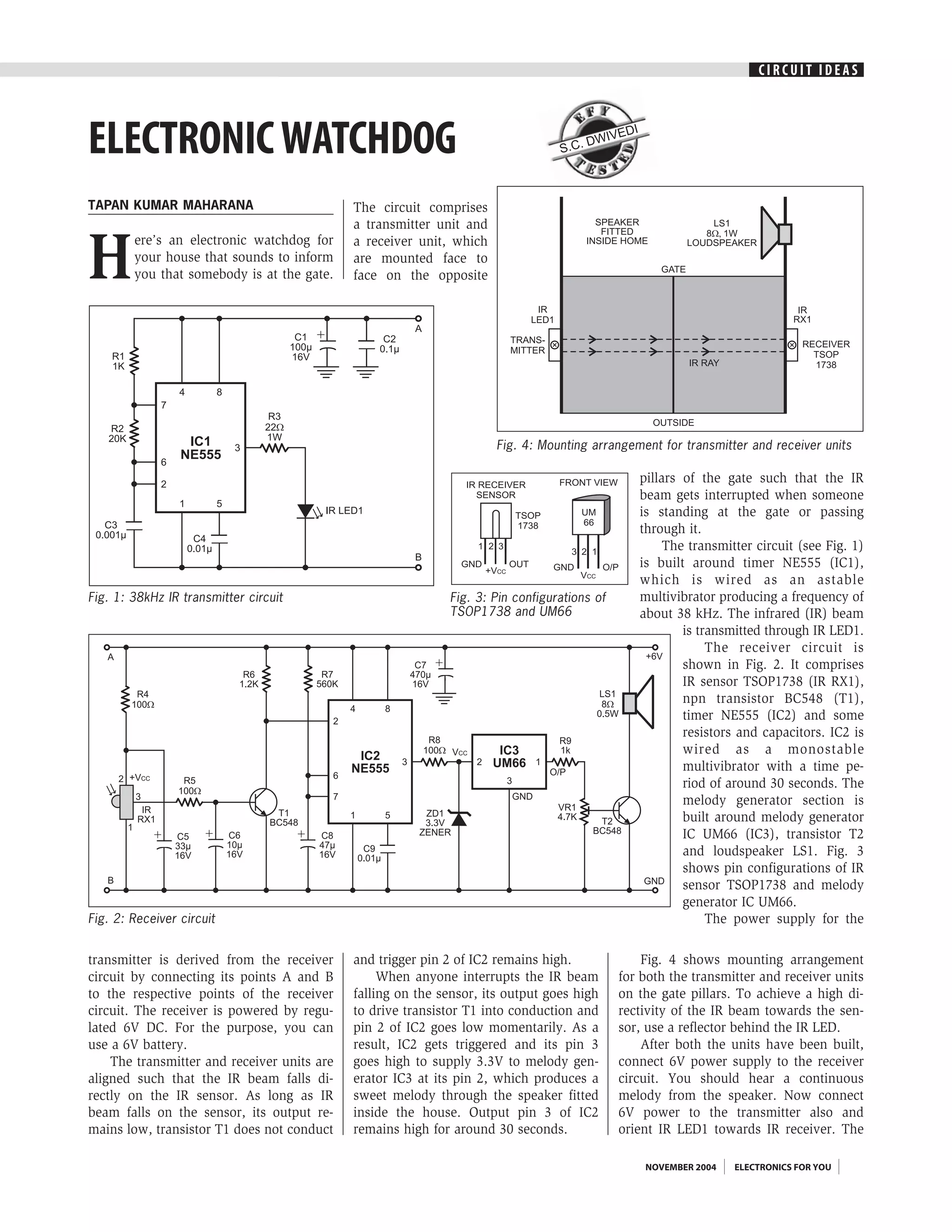
CIRCUIT IDEAS


ELECTRONIC WATCHDOG                                                              S.C.
                                                                                      DWI
                                                                                         VED
                                                                                            I


TAPAN KUMAR MAHARANA                         The circuit comprises
                                             a transmitter unit and


H
        ere’s an electronic watchdog for     a receiver unit, which
        your house that sounds to inform     are mounted face to
        you that somebody is at the gate.    face on the opposite


                                                                      Fig. 4: Mounting arrangement for transmitter and receiver units

                                                                                                pillars of the gate such that the IR
                                                                                                beam gets interrupted when someone
                                                                                                is standing at the gate or passing
                                                                                                through it.
                                                                                                     The transmitter circuit (see Fig. 1)
                                                                                                is built around timer NE555 (IC1),
                                                                                                which is wired as an astable
Fig. 1: 38kHz IR transmitter circuit                         Fig. 3: Pin configurations of      multivibrator producing a frequency of
                                                             TSOP1738 and UM66                  about 38 kHz. The infrared (IR) beam
                                                                                                        is transmitted through IR LED1.
                                                                                                             The receiver circuit is
                                                                                                        shown in Fig. 2. It comprises
                                                                                                        IR sensor TSOP1738 (IR RX1),
                                                                                                        npn transistor BC548 (T1),
                                                                                                        timer NE555 (IC2) and some
                                                                                                        resistors and capacitors. IC2 is
                                                                                                        wired as a monostable
                                                                                                        multivibrator with a time pe-
                                                                                                        riod of around 30 seconds. The
                                                                                                        melody generator section is
                                                                                                        built around melody generator
                                                                                                        IC UM66 (IC3), transistor T2
                                                                                                        and loudspeaker LS1. Fig. 3
                                                                                                        shows pin configurations of IR
                                                                                                        sensor TSOP1738 and melody
                                                                                                        generator IC UM66.
Fig. 2: Receiver circuit                                                                                     The power supply for the

transmitter is derived from the receiver     and trigger pin 2 of IC2 remains high.              Fig. 4 shows mounting arrangement
circuit by connecting its points A and B          When anyone interrupts the IR beam         for both the transmitter and receiver units
to the respective points of the receiver     falling on the sensor, its output goes high     on the gate pillars. To achieve a high di-
circuit. The receiver is powered by regu-    to drive transistor T1 into conduction and      rectivity of the IR beam towards the sen-
lated 6V DC. For the purpose, you can        pin 2 of IC2 goes low momentarily. As a         sor, use a reflector behind the IR LED.
use a 6V battery.                            result, IC2 gets triggered and its pin 3            After both the units have been built,
    The transmitter and receiver units are   goes high to supply 3.3V to melody gen-         connect 6V power supply to the receiver
aligned such that the IR beam falls di-      erator IC3 at its pin 2, which produces a       circuit. You should hear a continuous
rectly on the IR sensor. As long as IR       sweet melody through the speaker fitted         melody from the speaker. Now connect
beam falls on the sensor, its output re-     inside the house. Output pin 3 of IC2           6V power to the transmitter also and
mains low, transistor T1 does not conduct    remains high for around 30 seconds.             orient IR LED1 towards IR receiver. The

                                                                                                 NOVEMBER 2004   ELECTRONICS FOR YOU
CIRCUIT IDEAS

melody should stop after about 30 sec-     door, the IR beam is interrupted and the      Using preset VR1, you can set the volume
onds. Now the transmitter and the re-      alarm sounds for 30 seconds. The alarm        of the loudspeaker.
ceiver units are ready for use.            keeps sounding as long as one stands              This circuit can also be used as a door-
    When somebody enters through the       between the transmitter and receiver units.   bell or burglar alarm.


     ELECTRONICS FOR YOU   NOVEMBER 2004

Electronic watchdog

  • 1.
    CIRCUIT IDEAS ELECTRONIC WATCHDOG S.C. DWI VED I TAPAN KUMAR MAHARANA The circuit comprises a transmitter unit and H ere’s an electronic watchdog for a receiver unit, which your house that sounds to inform are mounted face to you that somebody is at the gate. face on the opposite Fig. 4: Mounting arrangement for transmitter and receiver units pillars of the gate such that the IR beam gets interrupted when someone is standing at the gate or passing through it. The transmitter circuit (see Fig. 1) is built around timer NE555 (IC1), which is wired as an astable Fig. 1: 38kHz IR transmitter circuit Fig. 3: Pin configurations of multivibrator producing a frequency of TSOP1738 and UM66 about 38 kHz. The infrared (IR) beam is transmitted through IR LED1. The receiver circuit is shown in Fig. 2. It comprises IR sensor TSOP1738 (IR RX1), npn transistor BC548 (T1), timer NE555 (IC2) and some resistors and capacitors. IC2 is wired as a monostable multivibrator with a time pe- riod of around 30 seconds. The melody generator section is built around melody generator IC UM66 (IC3), transistor T2 and loudspeaker LS1. Fig. 3 shows pin configurations of IR sensor TSOP1738 and melody generator IC UM66. Fig. 2: Receiver circuit The power supply for the transmitter is derived from the receiver and trigger pin 2 of IC2 remains high. Fig. 4 shows mounting arrangement circuit by connecting its points A and B When anyone interrupts the IR beam for both the transmitter and receiver units to the respective points of the receiver falling on the sensor, its output goes high on the gate pillars. To achieve a high di- circuit. The receiver is powered by regu- to drive transistor T1 into conduction and rectivity of the IR beam towards the sen- lated 6V DC. For the purpose, you can pin 2 of IC2 goes low momentarily. As a sor, use a reflector behind the IR LED. use a 6V battery. result, IC2 gets triggered and its pin 3 After both the units have been built, The transmitter and receiver units are goes high to supply 3.3V to melody gen- connect 6V power supply to the receiver aligned such that the IR beam falls di- erator IC3 at its pin 2, which produces a circuit. You should hear a continuous rectly on the IR sensor. As long as IR sweet melody through the speaker fitted melody from the speaker. Now connect beam falls on the sensor, its output re- inside the house. Output pin 3 of IC2 6V power to the transmitter also and mains low, transistor T1 does not conduct remains high for around 30 seconds. orient IR LED1 towards IR receiver. The NOVEMBER 2004 ELECTRONICS FOR YOU
  • 2.
    CIRCUIT IDEAS melody shouldstop after about 30 sec- door, the IR beam is interrupted and the Using preset VR1, you can set the volume onds. Now the transmitter and the re- alarm sounds for 30 seconds. The alarm of the loudspeaker. ceiver units are ready for use. keeps sounding as long as one stands This circuit can also be used as a door- When somebody enters through the between the transmitter and receiver units. bell or burglar alarm. ELECTRONICS FOR YOU NOVEMBER 2004