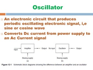
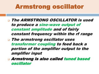
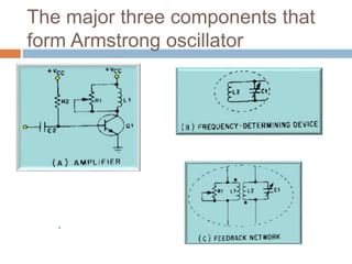
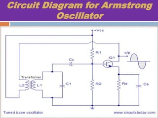
Oscillator
 An electronic circuit that produces
periodic oscillating electronic signal, i,e
sine or cosine wave
 Converts Dc current from power supply to
an Ac Current signal
Armstrong oscillator
 The ARMSTRONG OSCILLATOR is used
to produce a sine-wave output of
constant amplitude and of fairly
constant frequency within the rf range
 The armstrong oscillator uses
transformer coupling to feed back a
portion of the amplifier output to the
amplifier input
 Armstrong is also called tuned based
oscillator
The major three components that
form Armstrong oscillator
A
m
p
l
i
f
i
e
r
Circuit Diagram for Armstrong
Oscillator
Component Description
In the circuit diagram, resistors R1 and R2 forms a voltage
divider bias for the transistor Q1.
Emitter resistor Re is meant for stabilizing the bias point.
 Ce is the emitter by-pass capacitor. Its job is to by-pass the
amplified AC signals from dropping across Re.
 Cc is a DC blocking capacitor. Its job is to prevent DC currents
from the tank circuit side from entering the base.
Primary coil (L1) of the transformer and the capacitor C1 forms
the tank circuit.
L2 is a tickler coil,the feedback signal needed to produce
oscillations is magnetically coupled into the tank inductor in the
input circuit by a "tickler coil"
OPERATION OF ARMSTRONG
 When power supply is applied, the transistor Q1
starts conducting and its collector current starts to
rise. From the circuit diagram, you can see that this
collector current actually flows through secondary
coil L2.
 This rise in current current through the secondary
induces some voltage across the primary coil L1 by
virtue of mutual induction. The secondary coil L2 is
also called “Tickler Coil”.
 At this time, two actions occur. First, resonant tank
capacitor C1 charges to this voltage; the tank circuit
now has stored energy. Second, coupling capacitor
C2 couples the positive signal to the base of Q1.
OPERATION…
 The process of coupling oscillations or signal to
base
 As in the tank circuit there are countinous oscillations produced
in such a way when capacitor is full charged it starts
discharging through L1 and current through L1 starts increasing
 When capacitor is fully discharged there’s no emf left to
maintain current through L1 so magnetic flux tends to collapse
and coil L1
 The coil L1 produces a back emf by virtue of self induction.
This back emf charges the capacitor C1 again. Then the
capacitor discharges through L1 and the cycle is repeated. The
repetitive charging and discharging cycles result in a series of
oscillations in the tank circuit.
 With a positive signal on its base, Q1 conducts harder. With Q1
conducting harder, more current flows through L2, a larger
voltage is induced into L1, and a larger positive signal is
coupled back to the base of Q1
 The transistor will continue to increase in conduction until it
reaches saturation.
 At saturation, the collector current of Q1 is at a maximum value
and cannot increase any further. With a steady current through
L2, the magnetic fields are not moving and no voltage is
induced into the tank circuit.
 With no external voltage applied, C1 acts as a voltage source
and discharges. As the voltage across C1 decreases, its energy
is transferred to the magnetic field of L1.
OPERATION…
 The coupling capacitor, Ce, has charged to approximately the
same voltage as C1. As C1 discharges, Ce discharges. The
primary discharge path for Ce is through R2 (shown by the
dashed arrow). As C2 discharges, the voltage drop across
R2 opposes the forward bias on Q1 and collector current
begins to decrease. This is caused by the decreasing positive
potential at the base of Q1.
 A decrease in collector current allows the magnetic field of L2
to collapse. The collapsing field of L2 induces a negative
voltage into the secondary which is coupled through Ce and
makes the base of Q1 more negative. This, again, is
regenerative action; it continues until Q1 is driven into cutoff.
 When Q1 is cut off, the tank circuit continues to flywheel, or
oscillate. The flywheel effect not only produces a sine-wave
signal, but it aids in keeping Q1 cut off. Without feedback, the
oscillations of L1 and C1 would dampen out after several
OPERATION…
Summary of ARMSTRONG
OSCILLATOR’s Operation
 The operation of the Armstrong oscillator is basically
this:
 Power applied to the transistor allows energy to be
applied to the tank circuit causing it to oscillate.
Once every cycle, the transistor conducts for a short
period of time (Class C operation) and returns
enough energy to the tank to ensure a constant
amplitude output signal.

Armstrong oscillator

  • 2.
    Oscillator  An electroniccircuit that produces periodic oscillating electronic signal, i,e sine or cosine wave  Converts Dc current from power supply to an Ac Current signal
  • 3.
    Armstrong oscillator  TheARMSTRONG OSCILLATOR is used to produce a sine-wave output of constant amplitude and of fairly constant frequency within the rf range  The armstrong oscillator uses transformer coupling to feed back a portion of the amplifier output to the amplifier input  Armstrong is also called tuned based oscillator
  • 4.
    The major threecomponents that form Armstrong oscillator A m p l i f i e r
  • 5.
    Circuit Diagram forArmstrong Oscillator
  • 6.
    Component Description In thecircuit diagram, resistors R1 and R2 forms a voltage divider bias for the transistor Q1. Emitter resistor Re is meant for stabilizing the bias point.  Ce is the emitter by-pass capacitor. Its job is to by-pass the amplified AC signals from dropping across Re.  Cc is a DC blocking capacitor. Its job is to prevent DC currents from the tank circuit side from entering the base. Primary coil (L1) of the transformer and the capacitor C1 forms the tank circuit. L2 is a tickler coil,the feedback signal needed to produce oscillations is magnetically coupled into the tank inductor in the input circuit by a "tickler coil"
  • 7.
    OPERATION OF ARMSTRONG When power supply is applied, the transistor Q1 starts conducting and its collector current starts to rise. From the circuit diagram, you can see that this collector current actually flows through secondary coil L2.  This rise in current current through the secondary induces some voltage across the primary coil L1 by virtue of mutual induction. The secondary coil L2 is also called “Tickler Coil”.  At this time, two actions occur. First, resonant tank capacitor C1 charges to this voltage; the tank circuit now has stored energy. Second, coupling capacitor C2 couples the positive signal to the base of Q1.
  • 8.
    OPERATION…  The processof coupling oscillations or signal to base  As in the tank circuit there are countinous oscillations produced in such a way when capacitor is full charged it starts discharging through L1 and current through L1 starts increasing  When capacitor is fully discharged there’s no emf left to maintain current through L1 so magnetic flux tends to collapse and coil L1  The coil L1 produces a back emf by virtue of self induction. This back emf charges the capacitor C1 again. Then the capacitor discharges through L1 and the cycle is repeated. The repetitive charging and discharging cycles result in a series of oscillations in the tank circuit.
  • 9.
     With apositive signal on its base, Q1 conducts harder. With Q1 conducting harder, more current flows through L2, a larger voltage is induced into L1, and a larger positive signal is coupled back to the base of Q1  The transistor will continue to increase in conduction until it reaches saturation.  At saturation, the collector current of Q1 is at a maximum value and cannot increase any further. With a steady current through L2, the magnetic fields are not moving and no voltage is induced into the tank circuit.  With no external voltage applied, C1 acts as a voltage source and discharges. As the voltage across C1 decreases, its energy is transferred to the magnetic field of L1. OPERATION…
  • 10.
     The couplingcapacitor, Ce, has charged to approximately the same voltage as C1. As C1 discharges, Ce discharges. The primary discharge path for Ce is through R2 (shown by the dashed arrow). As C2 discharges, the voltage drop across R2 opposes the forward bias on Q1 and collector current begins to decrease. This is caused by the decreasing positive potential at the base of Q1.  A decrease in collector current allows the magnetic field of L2 to collapse. The collapsing field of L2 induces a negative voltage into the secondary which is coupled through Ce and makes the base of Q1 more negative. This, again, is regenerative action; it continues until Q1 is driven into cutoff.  When Q1 is cut off, the tank circuit continues to flywheel, or oscillate. The flywheel effect not only produces a sine-wave signal, but it aids in keeping Q1 cut off. Without feedback, the oscillations of L1 and C1 would dampen out after several OPERATION…
  • 11.
    Summary of ARMSTRONG OSCILLATOR’sOperation  The operation of the Armstrong oscillator is basically this:  Power applied to the transistor allows energy to be applied to the tank circuit causing it to oscillate. Once every cycle, the transistor conducts for a short period of time (Class C operation) and returns enough energy to the tank to ensure a constant amplitude output signal.