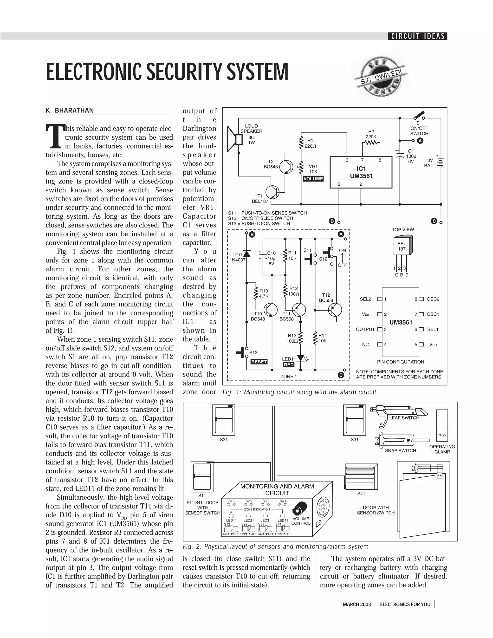
CIRCUIT IDEAS


ELECTRONIC SECURITY SYSTEM                                                                                   S.C. D
                                                                                                                   WIVE
                                                                                                                       DI


K. BHARATHAN                                     output of
                                                 t    h     e


T
        his reliable and easy-to-operate elec-   Darlington
        tronic security system can be used       pair drives
        in banks, factories, commercial es-      the loud-
tablishments, houses, etc.                       speaker
     The system comprises a monitoring sys-      whose out-
tem and several sensing zones. Each sens-        put volume
ing zone is provided with a closed-loop          can be con-
switch known as sense switch. Sense              trolled by
switches are fixed on the doors of premises      potentiom-
under security and connected to the moni-        eter VR1.
toring system. As long as the doors are          Capacitor
closed, sense switches are also closed. The      C1 serves
monitoring system can be installed at a          as a filter
convenient central place for easy operation.     capacitor.
     Fig. 1 shows the monitoring circuit             Y o u
only for zone 1 along with the common            can alter
alarm circuit. For other zones, the              the alarm
monitoring circuit is identical, with only       sound as
the prefixes of components changing              desired by
as per zone number. Encircled points A,          changing
B, and C of each zone monitoring circuit         the con-
need to be joined to the corresponding           nections of
points of the alarm circuit (upper half          IC1       as
of Fig. 1).                                      shown in
     When zone 1 sensing switch S11, zone        the table.
on/off slide switch S12, and system on/off           T h e
switch S1 are all on, pnp transistor T12         circuit con-
reverse biases to go in cut-off condition,       tinues to
with its collector at around 0 volt. When        sound the
the door fitted with sensor switch S11 is        alarm until
opened, transistor T12 gets forward biased       zone door Fig. 1: Monitoring circuit along with the alarm circuit
and it conducts. Its collector voltage goes
high, which forward biases transistor T10
via resistor R10 to turn it on. (Capacitor
C10 serves as a filter capacitor.) As a re-
sult, the collector voltage of transistor T10
falls to forward bias transistor T11, which
conducts and its collector voltage is sus-
tained at a high level. Under this latched
condition, sensor switch S11 and the state
of transistor T12 have no effect. In this
state, red LED11 of the zone remains lit.
     Simultaneously, the high-level voltage
from the collector of transistor T11 via di-
ode D10 is applied to VDD pin 5 of siren
sound generator IC1 (UM3561) whose pin
2 is grounded. Resistor R3 connected across
pins 7 and 8 of IC1 determines the fre-
                                                 Fig. 2: Physical layout of sensors and monitoring/alarm system
quency of the in-built oscillator. As a re-
sult, IC1 starts generating the audio signal     is closed (to close switch S11) and the           The system operates off a 3V DC bat-
output at pin 3. The output voltage from         reset switch is pressed momentarily (which    tery or recharging battery with charging
IC1 is further amplified by Darlington pair      causes transistor T10 to cut off, returning   circuit or battery eliminator. If desired,
of transistors T1 and T2. The amplified          the circuit to its initial state).            more operating zones can be added.

                                                                                                      MARCH 2003     ELECTRONICS FOR YOU
CIRCUIT IDEAS

Alarm sound                              Circuit connections               for respective        ing to the zone glows to indicate that the
                                                                           zones in closed       door of the zone is open. The alarm and
                        IC pin 1 connected to IC pin 6 connected to        position. Also        the LED indication will continue even af-
Police siren                       NC                      NC              keep zone slide       ter that particular door with the sensing
Ambulance siren                    NC                      VDD             switches S12, S22,    switch is immediately closed, or even if
Fire engine Sound                  NC                      VSS             S32, S42, etc in      that switch is removed/damaged or con-
Machinegun sound                   VSS                     NC              ‘on’ position. This   necting wire is cut open.
                                                                           puts the system in        Any particular zone in the monitoring
Note. NC indicates no connection
                                                                           operation, guard-     system can be put to operation or out of
                                                                           ing all the zone      operation by switching on or switching off
    Initially keep the monitoring system            doors.                                       the corresponding slide switch in the moni-
switch S1 off. Keep all the zone doors fixed            Now, if the door of a particular zone    toring system.
with sensing switches S11, S21, S31, S41,           is opened, the monitoring system sounds          The circuit for monitoring four zones
etc closed. This keeps the sensing switches         an audible alarm and the LED correspond-     costs around Rs 400.


      ELECTRONICS FOR YOU      MARCH 2003

Electronic security system

  • 1.
    CIRCUIT IDEAS ELECTRONIC SECURITYSYSTEM S.C. D WIVE DI K. BHARATHAN output of t h e T his reliable and easy-to-operate elec- Darlington tronic security system can be used pair drives in banks, factories, commercial es- the loud- tablishments, houses, etc. speaker The system comprises a monitoring sys- whose out- tem and several sensing zones. Each sens- put volume ing zone is provided with a closed-loop can be con- switch known as sense switch. Sense trolled by switches are fixed on the doors of premises potentiom- under security and connected to the moni- eter VR1. toring system. As long as the doors are Capacitor closed, sense switches are also closed. The C1 serves monitoring system can be installed at a as a filter convenient central place for easy operation. capacitor. Fig. 1 shows the monitoring circuit Y o u only for zone 1 along with the common can alter alarm circuit. For other zones, the the alarm monitoring circuit is identical, with only sound as the prefixes of components changing desired by as per zone number. Encircled points A, changing B, and C of each zone monitoring circuit the con- need to be joined to the corresponding nections of points of the alarm circuit (upper half IC1 as of Fig. 1). shown in When zone 1 sensing switch S11, zone the table. on/off slide switch S12, and system on/off T h e switch S1 are all on, pnp transistor T12 circuit con- reverse biases to go in cut-off condition, tinues to with its collector at around 0 volt. When sound the the door fitted with sensor switch S11 is alarm until opened, transistor T12 gets forward biased zone door Fig. 1: Monitoring circuit along with the alarm circuit and it conducts. Its collector voltage goes high, which forward biases transistor T10 via resistor R10 to turn it on. (Capacitor C10 serves as a filter capacitor.) As a re- sult, the collector voltage of transistor T10 falls to forward bias transistor T11, which conducts and its collector voltage is sus- tained at a high level. Under this latched condition, sensor switch S11 and the state of transistor T12 have no effect. In this state, red LED11 of the zone remains lit. Simultaneously, the high-level voltage from the collector of transistor T11 via di- ode D10 is applied to VDD pin 5 of siren sound generator IC1 (UM3561) whose pin 2 is grounded. Resistor R3 connected across pins 7 and 8 of IC1 determines the fre- Fig. 2: Physical layout of sensors and monitoring/alarm system quency of the in-built oscillator. As a re- sult, IC1 starts generating the audio signal is closed (to close switch S11) and the The system operates off a 3V DC bat- output at pin 3. The output voltage from reset switch is pressed momentarily (which tery or recharging battery with charging IC1 is further amplified by Darlington pair causes transistor T10 to cut off, returning circuit or battery eliminator. If desired, of transistors T1 and T2. The amplified the circuit to its initial state). more operating zones can be added. MARCH 2003 ELECTRONICS FOR YOU
  • 2.
    CIRCUIT IDEAS Alarm sound Circuit connections for respective ing to the zone glows to indicate that the zones in closed door of the zone is open. The alarm and IC pin 1 connected to IC pin 6 connected to position. Also the LED indication will continue even af- Police siren NC NC keep zone slide ter that particular door with the sensing Ambulance siren NC VDD switches S12, S22, switch is immediately closed, or even if Fire engine Sound NC VSS S32, S42, etc in that switch is removed/damaged or con- Machinegun sound VSS NC ‘on’ position. This necting wire is cut open. puts the system in Any particular zone in the monitoring Note. NC indicates no connection operation, guard- system can be put to operation or out of ing all the zone operation by switching on or switching off Initially keep the monitoring system doors. the corresponding slide switch in the moni- switch S1 off. Keep all the zone doors fixed Now, if the door of a particular zone toring system. with sensing switches S11, S21, S31, S41, is opened, the monitoring system sounds The circuit for monitoring four zones etc closed. This keeps the sensing switches an audible alarm and the LED correspond- costs around Rs 400. ELECTRONICS FOR YOU MARCH 2003