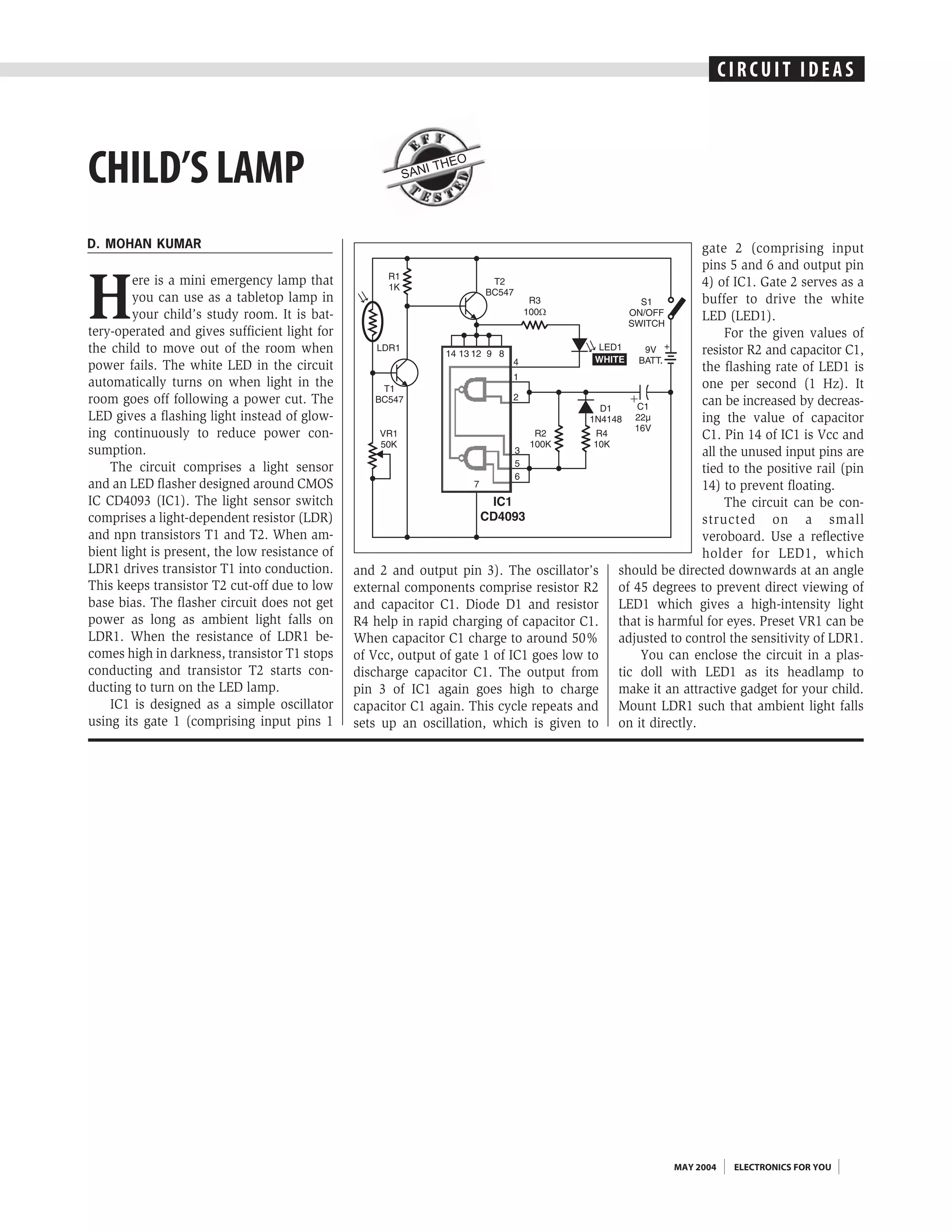
C I R CCURICTU IITDIE AASS
                                                                                                                           I           DE


CHILD’S LAMP                                            SAN
                                                              I THE
                                                                      O


D. MOHAN KUMAR                                                                                                gate 2 (comprising input
                                                                                                              pins 5 and 6 and output pin


H
         ere is a mini emergency lamp that                                                                    4) of IC1. Gate 2 serves as a
         you can use as a tabletop lamp in                                                                    buffer to drive the white
         your child’s study room. It is bat-                                                                  LED (LED1).
tery-operated and gives sufficient light for                                                                       For the given values of
the child to move out of the room when                                                                        resistor R2 and capacitor C1,
power fails. The white LED in the circuit                                                                     the flashing rate of LED1 is
automatically turns on when light in the                                                                      one per second (1 Hz). It
room goes off following a power cut. The                                                                      can be increased by decreas-
LED gives a flashing light instead of glow-                                                                   ing the value of capacitor
ing continuously to reduce power con-                                                                         C1. Pin 14 of IC1 is Vcc and
sumption.                                                                                                     all the unused input pins are
    The circuit comprises a light sensor                                                                      tied to the positive rail (pin
and an LED flasher designed around CMOS                                                                       14) to prevent floating.
IC CD4093 (IC1). The light sensor switch                                                                           The circuit can be con-
comprises a light-dependent resistor (LDR)                                                                    structed on a small
and npn transistors T1 and T2. When am-                                                                       veroboard. Use a reflective
bient light is present, the low resistance of                                                                 holder for LED1, which
LDR1 drives transistor T1 into conduction.      and 2 and output pin 3). The oscillator’s     should be directed downwards at an angle
This keeps transistor T2 cut-off due to low     external components comprise resistor R2      of 45 degrees to prevent direct viewing of
base bias. The flasher circuit does not get     and capacitor C1. Diode D1 and resistor       LED1 which gives a high-intensity light
power as long as ambient light falls on         R4 help in rapid charging of capacitor C1.    that is harmful for eyes. Preset VR1 can be
LDR1. When the resistance of LDR1 be-           When capacitor C1 charge to around 50%        adjusted to control the sensitivity of LDR1.
comes high in darkness, transistor T1 stops     of Vcc, output of gate 1 of IC1 goes low to       You can enclose the circuit in a plas-
conducting and transistor T2 starts con-        discharge capacitor C1. The output from       tic doll with LED1 as its headlamp to
ducting to turn on the LED lamp.                pin 3 of IC1 again goes high to charge        make it an attractive gadget for your child.
    IC1 is designed as a simple oscillator      capacitor C1 again. This cycle repeats and    Mount LDR1 such that ambient light falls
using its gate 1 (comprising input pins 1       sets up an oscillation, which is given to     on it directly.


                                                                                                        MAY 2004      ELECTRONICS FOR YOU

Child's lamp

  • 1.
    C I RCCURICTU IITDIE AASS I DE CHILD’S LAMP SAN I THE O D. MOHAN KUMAR gate 2 (comprising input pins 5 and 6 and output pin H ere is a mini emergency lamp that 4) of IC1. Gate 2 serves as a you can use as a tabletop lamp in buffer to drive the white your child’s study room. It is bat- LED (LED1). tery-operated and gives sufficient light for For the given values of the child to move out of the room when resistor R2 and capacitor C1, power fails. The white LED in the circuit the flashing rate of LED1 is automatically turns on when light in the one per second (1 Hz). It room goes off following a power cut. The can be increased by decreas- LED gives a flashing light instead of glow- ing the value of capacitor ing continuously to reduce power con- C1. Pin 14 of IC1 is Vcc and sumption. all the unused input pins are The circuit comprises a light sensor tied to the positive rail (pin and an LED flasher designed around CMOS 14) to prevent floating. IC CD4093 (IC1). The light sensor switch The circuit can be con- comprises a light-dependent resistor (LDR) structed on a small and npn transistors T1 and T2. When am- veroboard. Use a reflective bient light is present, the low resistance of holder for LED1, which LDR1 drives transistor T1 into conduction. and 2 and output pin 3). The oscillator’s should be directed downwards at an angle This keeps transistor T2 cut-off due to low external components comprise resistor R2 of 45 degrees to prevent direct viewing of base bias. The flasher circuit does not get and capacitor C1. Diode D1 and resistor LED1 which gives a high-intensity light power as long as ambient light falls on R4 help in rapid charging of capacitor C1. that is harmful for eyes. Preset VR1 can be LDR1. When the resistance of LDR1 be- When capacitor C1 charge to around 50% adjusted to control the sensitivity of LDR1. comes high in darkness, transistor T1 stops of Vcc, output of gate 1 of IC1 goes low to You can enclose the circuit in a plas- conducting and transistor T2 starts con- discharge capacitor C1. The output from tic doll with LED1 as its headlamp to ducting to turn on the LED lamp. pin 3 of IC1 again goes high to charge make it an attractive gadget for your child. IC1 is designed as a simple oscillator capacitor C1 again. This cycle repeats and Mount LDR1 such that ambient light falls using its gate 1 (comprising input pins 1 sets up an oscillation, which is given to on it directly. MAY 2004 ELECTRONICS FOR YOU