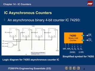
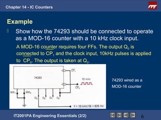
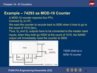
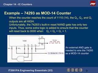
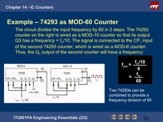
IT2001PA
Engineering Essentials (2/2)


Chapter 14 - IC Counters

 Lecturer Name
lecturer_email@ite.edu.sg
                            Nov 20, 2012
Contact Number
Chapter 14 - IC Counters


Lesson Objectives
Upon completion of this topic, you should be able to:
   Students should be able to design simple
    synchronous/asynchronous counters using MSI chips.


    IT2001PA Engineering Essentials (2/2)           2
Chapter 14 - IC Counters


Specific Objectives
  Students should be able to :
   State some common MSI synchronous/asynchronous
    counter chips.
      Write down the control pins to select various functions
       on an MSI chip.
      State the functions of the various control pins.
      Design simple synchronous up/down counters based
       on given MSI technical reference.


      IT2001PA Engineering Essentials (2/2)
Chapter 14 - IC Counters


 IC Asynchronous Counters
    An asynchronous binary 4-bit counter IC 74293:


                                                        74293
                                                          74193               CP1
                                                       Binary 4-bit
                                                        Counter               CP0


                                                  MR1 MR2 Q3 Q2 Q1 Q0
                                                        (MSB)         (LSB)

                                                  Simplified symbol for 74293
Logic diagram for 74293 asynchronous counter IC


     IT2001PA Engineering Essentials (2/2)                                4
Chapter 14 - IC Counters


Description of 74293
   It has four J-K FFs with outputs Q0, Q1, Q2, Q3 where Q0 is the LBS
    and Q3 is the MSB.
   Each FF has a CP (clock pulse) input which is activated by
    negative-edge transition (NGT).
   Each FF has an asynchronous CLEAR input, C0.
   These are connected together to the output of a two-input NAND
    gate with inputs MR1 and MR2, where MR means master reset.
    Both MR inputs must be HIGH to clear the counter to 0000.
   FFs Q1, Q2 and Q3 are already connected as a 3-bit ripple counter.
    FF Q0 is not connected to anything internally.


    IT2001PA Engineering Essentials (2/2)                        5
Chapter 14 - IC Counters


Example
    Show how the 74293 should be connected to operate
     as a MOD-16 counter with a 10 kHz clock input.
     A MOD-16 counter requires four FFs. The output Q0 is
     connected to CP1 and the clock input, 10kHz pulses is applied
     to CP0. The output is taken at Q3.


                                                74293 wired as a
                                                MOD-16 counter


    IT2001PA Engineering Essentials (2/2)                      6
Chapter 14 - IC Counters


Example
    Show how to wire the 74293(s) as a
        a)   MOD-10 counter
        b)   MOD-14 counter
        c)   MOD-60 counter


    IT2001PA Engineering Essentials (2/2)   7
Chapter 14 - IC Counters


Example – 74293 as MOD-10 Counter
    A MOD-10 counter requires four FFs.
    Connect Q0 to CP1.
    We want the counter to recycle back to 0000 when it tries to go to
    the count of 1010 (ten).
    Thus, Q3 and Q1 outputs have to be connected to the master reset
    inputs; when they both go HIGH at the count of 1010, the NAND
    output will immediately reset the counter to 0000.


                                                 74293 wired as a
                                                 MOD-10 counter


    IT2001PA Engineering Essentials (2/2)                           8
Chapter 14 - IC Counters


Example – 74293 as MOD-14 Counter
    When the counter reaches the count of 1110 (14), the Q3, Q2, and Q1
    outputs are all HIGH.
    Unfortunately, the 74293’s built-in reset NAND gate has only two
    inputs. Thus, some extra logic is added to ensure that the counter
    will reset back to 0000 when Q3 = Q2 = Q1 = 1.


                                                 An external AND gate is
                                                 needed to wire the 74293
                                                 as a MOD-14 counter


    IT2001PA Engineering Essentials (2/2)                         9
Chapter 14 - IC Counters


Example – 74293 as MOD-60 Counter
    The circuit divides the input frequency by 60 in 2 steps. The 74293
    counter on the right is wired as a MOD-10 counter so that its output
    Q3 has a frequency = fin/10. The signal is connected to the CP1 input
    of the second 74293 counter, which is wired as a MOD-6 counter.
    Thus, the Q3 output of the second counter will have a frequency:

                                                                fin/10
                                                          fout =
                                                                  6
                                                                 f
                                                              = in
                                                                 60

                                                   Two 74293s can be
                                                   combined to provide a
                                                   frequency division of 60


    IT2001PA Engineering Essentials (2/2)                             10
Chapter 14 - IC Counters


Next Lesson


    IT2001PA Engineering Essentials (2/2)   11

Ee2 chapter14 ic_counters

  • 1.
    IT2001PA Engineering Essentials (2/2) Chapter14 - IC Counters Lecturer Name lecturer_email@ite.edu.sg Nov 20, 2012 Contact Number
  • 2.
    Chapter 14 -IC Counters Lesson Objectives Upon completion of this topic, you should be able to:  Students should be able to design simple synchronous/asynchronous counters using MSI chips. IT2001PA Engineering Essentials (2/2) 2
  • 3.
    Chapter 14 -IC Counters Specific Objectives Students should be able to :  State some common MSI synchronous/asynchronous counter chips.  Write down the control pins to select various functions on an MSI chip.  State the functions of the various control pins.  Design simple synchronous up/down counters based on given MSI technical reference. IT2001PA Engineering Essentials (2/2)
  • 4.
    Chapter 14 -IC Counters IC Asynchronous Counters  An asynchronous binary 4-bit counter IC 74293: 74293 74193 CP1 Binary 4-bit Counter CP0 MR1 MR2 Q3 Q2 Q1 Q0 (MSB) (LSB) Simplified symbol for 74293 Logic diagram for 74293 asynchronous counter IC IT2001PA Engineering Essentials (2/2) 4
  • 5.
    Chapter 14 -IC Counters Description of 74293  It has four J-K FFs with outputs Q0, Q1, Q2, Q3 where Q0 is the LBS and Q3 is the MSB.  Each FF has a CP (clock pulse) input which is activated by negative-edge transition (NGT).  Each FF has an asynchronous CLEAR input, C0.  These are connected together to the output of a two-input NAND gate with inputs MR1 and MR2, where MR means master reset. Both MR inputs must be HIGH to clear the counter to 0000.  FFs Q1, Q2 and Q3 are already connected as a 3-bit ripple counter. FF Q0 is not connected to anything internally. IT2001PA Engineering Essentials (2/2) 5
  • 6.
    Chapter 14 -IC Counters Example  Show how the 74293 should be connected to operate as a MOD-16 counter with a 10 kHz clock input. A MOD-16 counter requires four FFs. The output Q0 is connected to CP1 and the clock input, 10kHz pulses is applied to CP0. The output is taken at Q3. 74293 wired as a MOD-16 counter IT2001PA Engineering Essentials (2/2) 6
  • 7.
    Chapter 14 -IC Counters Example  Show how to wire the 74293(s) as a a) MOD-10 counter b) MOD-14 counter c) MOD-60 counter IT2001PA Engineering Essentials (2/2) 7
  • 8.
    Chapter 14 -IC Counters Example – 74293 as MOD-10 Counter A MOD-10 counter requires four FFs. Connect Q0 to CP1. We want the counter to recycle back to 0000 when it tries to go to the count of 1010 (ten). Thus, Q3 and Q1 outputs have to be connected to the master reset inputs; when they both go HIGH at the count of 1010, the NAND output will immediately reset the counter to 0000. 74293 wired as a MOD-10 counter IT2001PA Engineering Essentials (2/2) 8
  • 9.
    Chapter 14 -IC Counters Example – 74293 as MOD-14 Counter When the counter reaches the count of 1110 (14), the Q3, Q2, and Q1 outputs are all HIGH. Unfortunately, the 74293’s built-in reset NAND gate has only two inputs. Thus, some extra logic is added to ensure that the counter will reset back to 0000 when Q3 = Q2 = Q1 = 1. An external AND gate is needed to wire the 74293 as a MOD-14 counter IT2001PA Engineering Essentials (2/2) 9
  • 10.
    Chapter 14 -IC Counters Example – 74293 as MOD-60 Counter The circuit divides the input frequency by 60 in 2 steps. The 74293 counter on the right is wired as a MOD-10 counter so that its output Q3 has a frequency = fin/10. The signal is connected to the CP1 input of the second 74293 counter, which is wired as a MOD-6 counter. Thus, the Q3 output of the second counter will have a frequency: fin/10 fout = 6 f = in 60 Two 74293s can be combined to provide a frequency division of 60 IT2001PA Engineering Essentials (2/2) 10
  • 11.
    Chapter 14 -IC Counters Next Lesson IT2001PA Engineering Essentials (2/2) 11