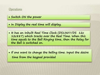
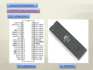
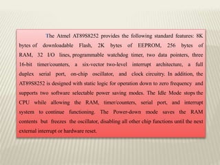
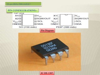
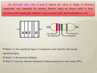
This document presents a project for an automatic college bell system. It uses a microcontroller and real-time clock to ring the bell according to a pre-programmed schedule, saving manpower costs compared to a manual system. The system consists of an AT89S8252 microcontroller, DS1307 real-time clock, 7805 voltage regulator, step-down transformer, crystal oscillator, relays, resistors, transistors, LEDs, seven segment displays, keypad, and buzzer. It is powered by a 5V supply and can accurately ring the bell according to the college timetable without needing a person to operate it manually.

![[Convention Bell] [Manually Operated College Bell]
Automatic College Bell](https://image.slidesharecdn.com/b658014a-3762-420f-b315-8d2d0576e752-150428010626-conversion-gate02/85/Presentation-4-320.jpg)
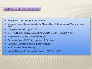
![78xx Ics have three terminals and are most commonly found in the TO220 form
factor, although smaller surface-mount and larger TO3 packages are also available from
some manufacturers. These devices typically support an input voltage which can be
anywhere from a couple of volts over the intended output voltage, up to a maximum
of 35 or 40 volts, and can typically provide up to around 1 or 1.5 amps of current
(though smaller or larger packages may have a lower or higher current rating).
[IC 7805]](https://image.slidesharecdn.com/b658014a-3762-420f-b315-8d2d0576e752-150428010626-conversion-gate02/85/Presentation-17-320.jpg)
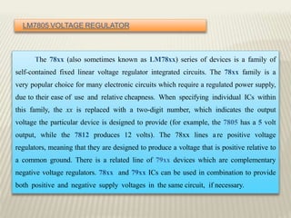
![[Step-Up Transformer]
[Step-Down Transformer]](https://image.slidesharecdn.com/b658014a-3762-420f-b315-8d2d0576e752-150428010626-conversion-gate02/85/Presentation-19-320.jpg)
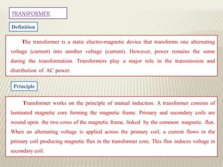
![CRYSTAL
A piezoelectric crystal is an electronic circuit that uses the mechanical resonance of a
vibrating crystal of piezoelectric material to create an electrical signal with a very precise
frequency. This frequency is commonly used to keep track of time (as in quartz
wristwatches), to provide a stable clock signal for digital integrated circuits, and to
stabilize frequencies for radio transmitters and receivers. The most common type of
piezoelectric resonator used is the quartz crystal, so oscillator circuits designed around
them were called "crystal oscillators".
[Crystal]](https://image.slidesharecdn.com/b658014a-3762-420f-b315-8d2d0576e752-150428010626-conversion-gate02/85/Presentation-20-320.jpg)
![DIODE
[Diode Symbol]](https://image.slidesharecdn.com/b658014a-3762-420f-b315-8d2d0576e752-150428010626-conversion-gate02/85/Presentation-21-320.jpg)
![[Diode]](https://image.slidesharecdn.com/b658014a-3762-420f-b315-8d2d0576e752-150428010626-conversion-gate02/85/Presentation-22-320.jpg)
![RELAY
[Relay]
In this circuit a 12V magnetic relay is used. In magnetic relay, insulated copper
wire coil is used to magnetize and attract the plunger. The plunger is normally
connected to N/C terminal. A spring is connected to attract the plunger upper side.
When output is received by relay, the plunger is attracted and the bulb glows.](https://image.slidesharecdn.com/b658014a-3762-420f-b315-8d2d0576e752-150428010626-conversion-gate02/85/Presentation-23-320.jpg)
![RESISTORS
A Resistor is a heat-dissipating element and in the electronic circuits it is mostly used
for either controlling the current in the circuit or developing a voltage drop across it, which
could be utilized for many applications. There are various types of resistors, which can be
classified according to a number of factors depending upon:
Material used for fabrication
Wattage and physical size
Intended application
Ambient temperature rating
Cost
[Resistor]](https://image.slidesharecdn.com/b658014a-3762-420f-b315-8d2d0576e752-150428010626-conversion-gate02/85/Presentation-24-320.jpg)
![TRANSISTOR
A Transistor consists of two junctions formed by sandwiching either p-type or n-
type semiconductor between a pair of opposite types. Accordingly, there are two types
of transistors namely: -
(1) n-p-n transistor (2) p-n-p transistor
[Transistors] [Transistor (BC 547)]](https://image.slidesharecdn.com/b658014a-3762-420f-b315-8d2d0576e752-150428010626-conversion-gate02/85/Presentation-26-320.jpg)
![CAPACITORS
The fundamental relation for the capacitance between two flat plates separated
by a dielectric material is given by: -
C=0.08854KA/D
Where: -
C= capacitance in pf.
K= dielectric constant
A=Area per plate in square cm.
D=Distance between two plates in cm
[Capacitor]](https://image.slidesharecdn.com/b658014a-3762-420f-b315-8d2d0576e752-150428010626-conversion-gate02/85/Presentation-27-320.jpg)
![LED (LIGHT EMITTING DIODE)
[Light Emitting Diode]](https://image.slidesharecdn.com/b658014a-3762-420f-b315-8d2d0576e752-150428010626-conversion-gate02/85/Presentation-28-320.jpg)
![SEVEN SEGMENT DISPLAY
[Seven Segment Display]
A seven segment display, as its name indicates, is composed of seven elements.
Individually on or off, they can be combined to produce simplified representations of the
Arabic numerals. Often the seven segments are arranged in an oblique (slanted) which aids
readability. Each of the numbers 0, 6,7and 9 may be represented by different glyphs on
seven-segment displays.](https://image.slidesharecdn.com/b658014a-3762-420f-b315-8d2d0576e752-150428010626-conversion-gate02/85/Presentation-29-320.jpg)
![KEYPAD (4*3)
[Keypad 4*3]
A simple 4x3 keyboard that allows data entry into bus based systems. Flow code
macros for driving this E-block are available.](https://image.slidesharecdn.com/b658014a-3762-420f-b315-8d2d0576e752-150428010626-conversion-gate02/85/Presentation-30-320.jpg)


![Embedded System[586]](https://cdn.slidesharecdn.com/ss_thumbnails/viisemesterindustrialtrainingreportpawan586-171104035355-thumbnail.jpg?width=640&height=640&fit=bounds)


