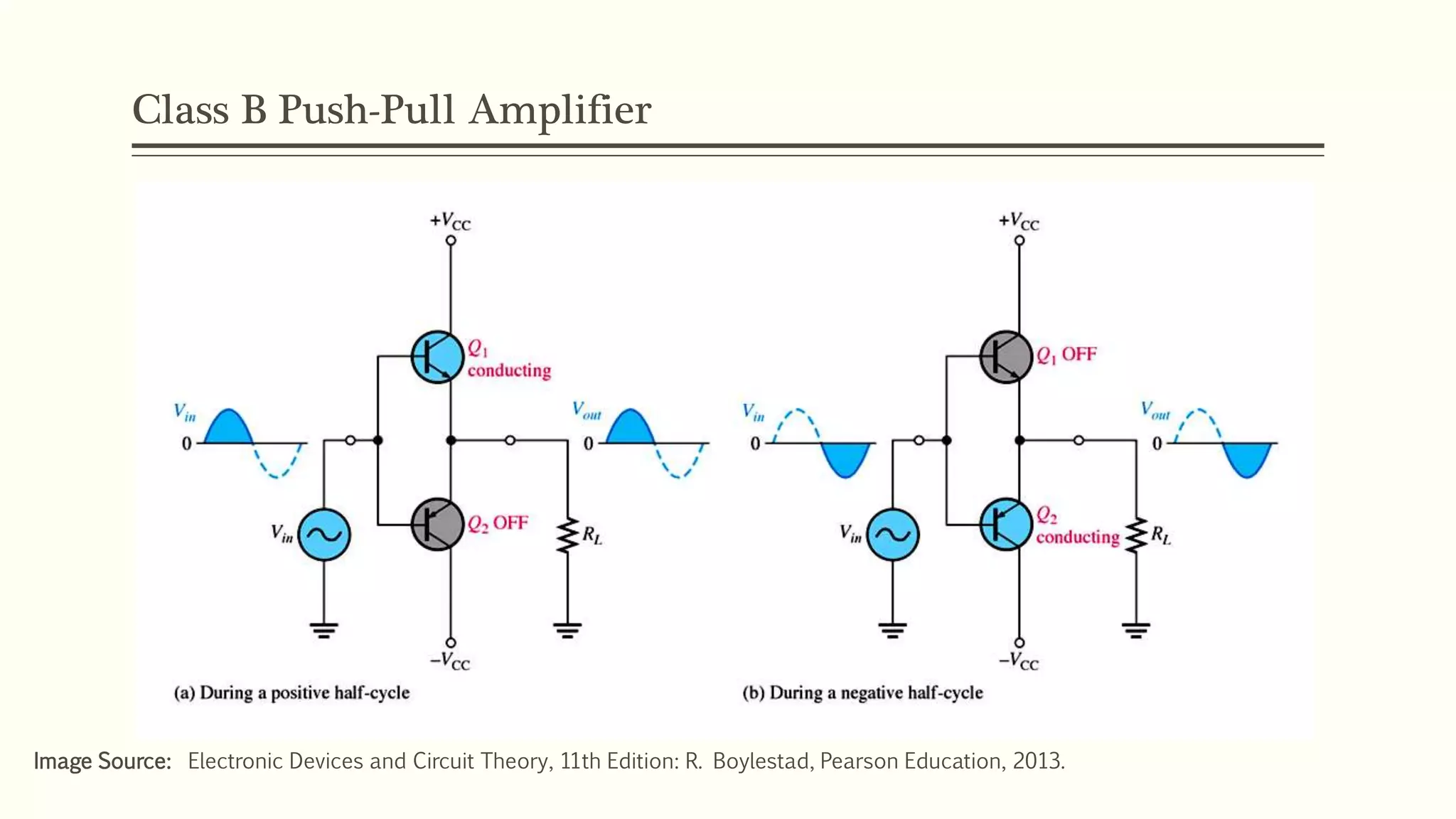
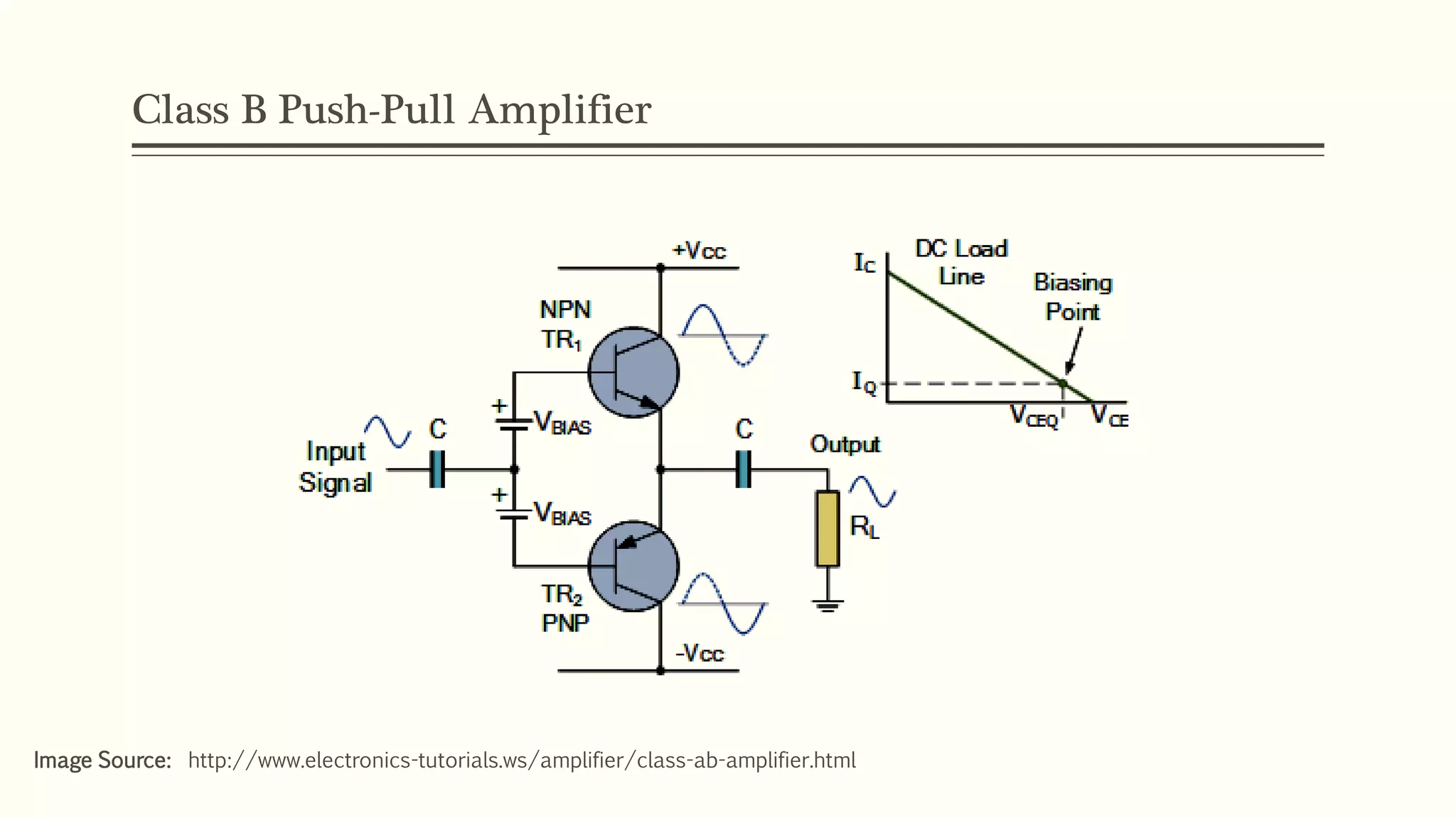
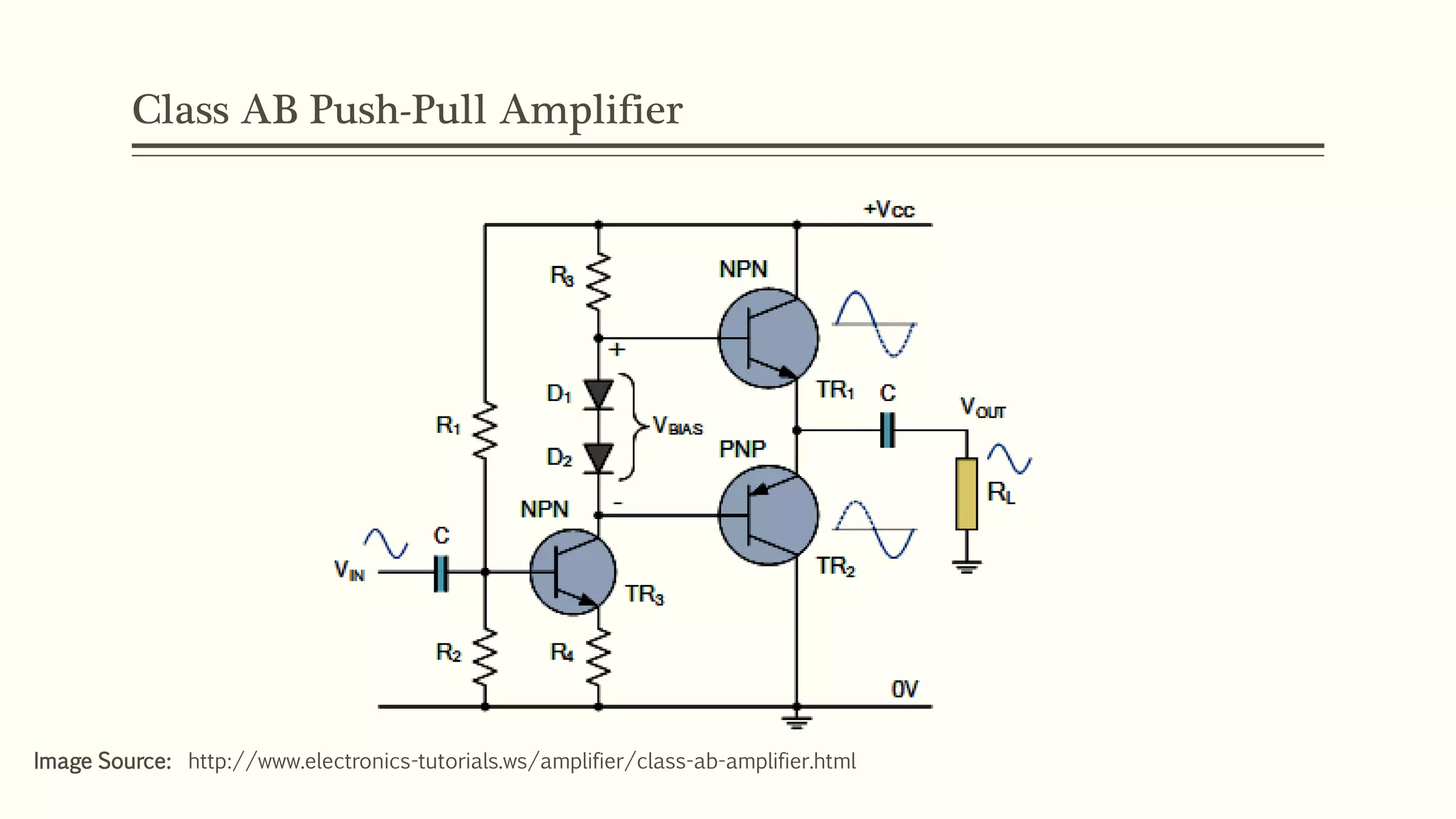
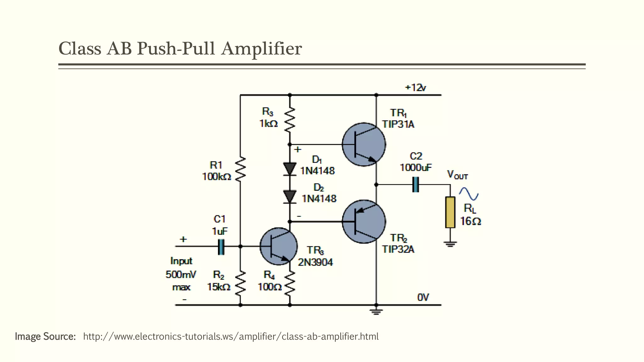
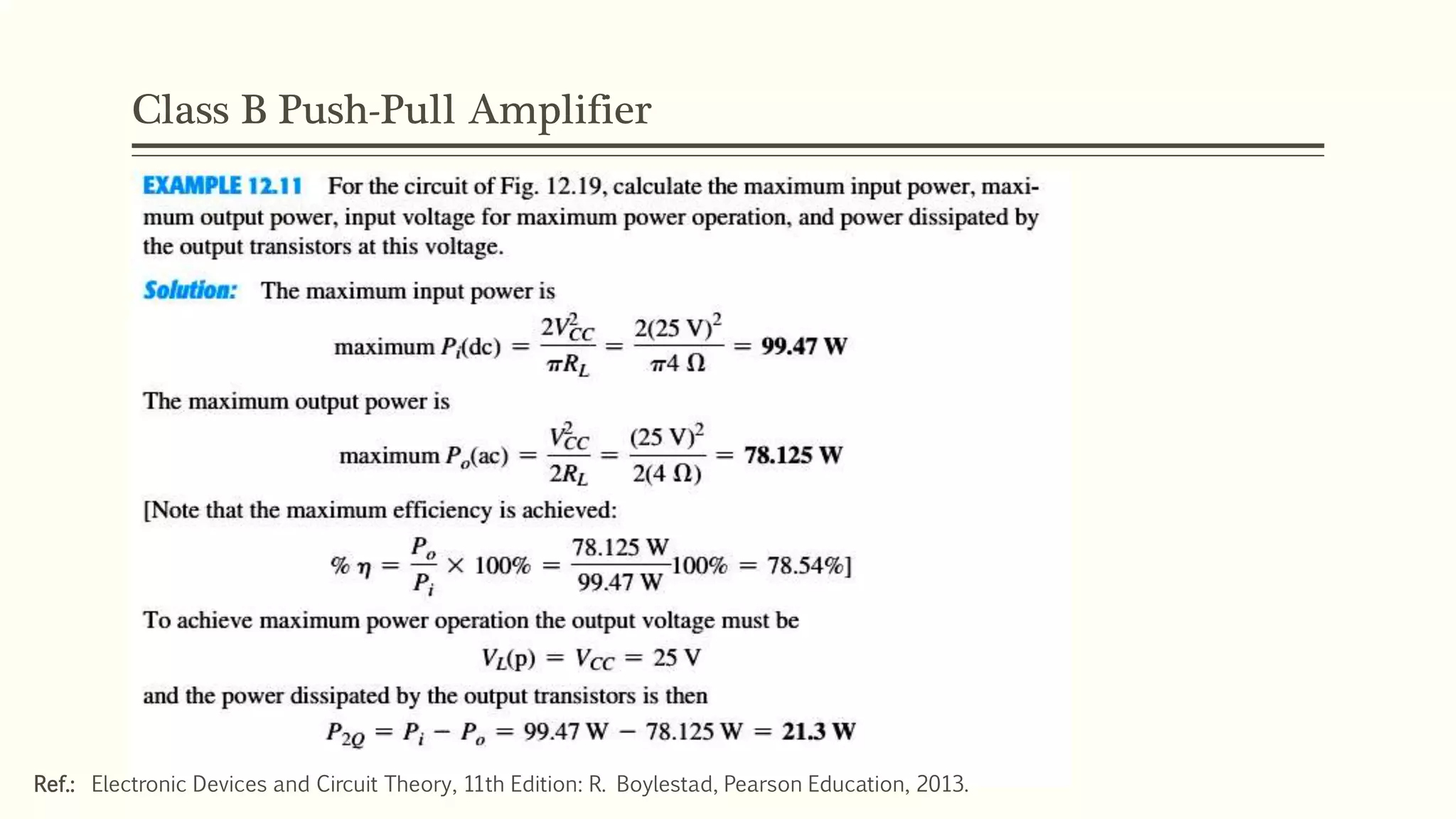
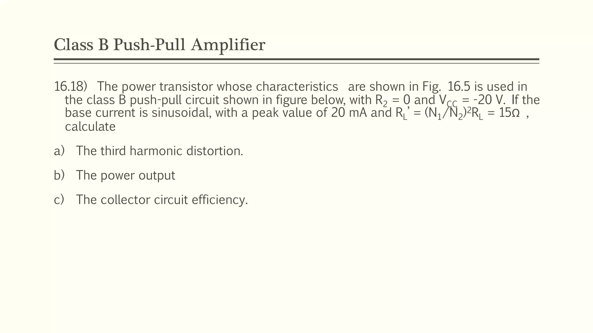
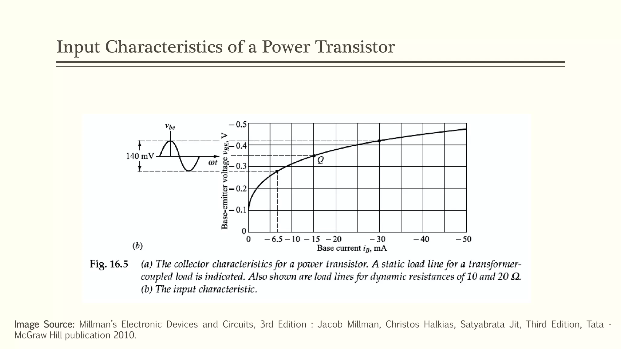
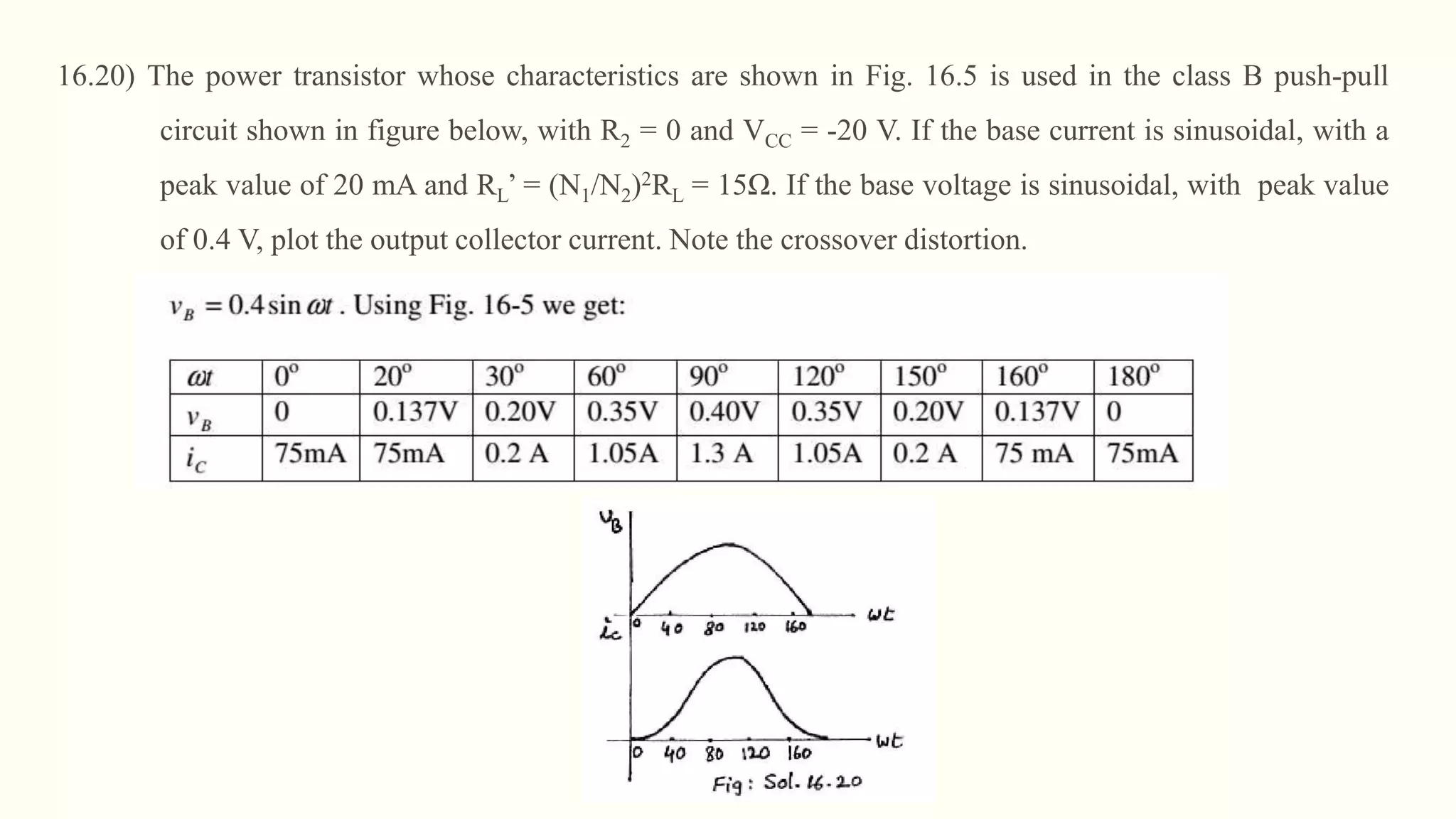
LARGE SIGNAL
AMPLIFIERS
Vikas R. Gupta
Electronics Engineering,
RCOEM, Nagpur.
Class B Push-Pull Amplifier
Two Transistors in Push-Pull Configuration
Image Source: Millman’s Electronic Devices and Circuits, 3rd Edition : Jacob Millman, Christos Halkias, Satyabrata Jit, Third Edition, Tata -
McGraw Hill publication 2010.
Class B Push-Pull Amplifier
Image Source: Millman’s Electronic Devices and Circuits, 3rd Edition : Jacob Millman, Christos Halkias, Satyabrata Jit, Third Edition, Tata -
McGraw Hill publication 2010.
Class B Push-Pull Amplifier
Image Source: Millman’s Electronic Devices and Circuits, 3rd Edition : Jacob Millman, Christos Halkias, Satyabrata Jit, Third Edition, Tata -
McGraw Hill publication 2010.
Class B Push-Pull Amplifier
Image Source: Electronic Devices and Circuit Theory, 11th Edition: R. Boylestad, Pearson Education, 2013.
Class B Push-Pull Amplifier
Image Source: Electronic Devices and Circuit Theory, 11th Edition: R. Boylestad, Pearson Education, 2013.
Class B Push-Pull Amplifier
Image Source: Millman’s Electronic Devices and Circuits, 3rd Edition : Jacob Millman, Christos Halkias, Satyabrata Jit, Third Edition, Tata -
McGraw Hill publication 2010.
Class B Push-Pull Amplifier
Image Source: Electronic Devices and Circuit Theory, 11th Edition: R. Boylestad, Pearson Education, 2013.
Class B Push-Pull Amplifier
Image Source: http://www.electronics-tutorials.ws/amplifier/class-ab-amplifier.html
Class AB Push-Pull Amplifier
Image Source: http://www.electronics-tutorials.ws/amplifier/class-ab-amplifier.html
Class AB Push-Pull Amplifier
Image Source: http://www.electronics-tutorials.ws/amplifier/class-ab-amplifier.html
Class AB Push-Pull Amplifier
Image Source: http://www.electronics-tutorials.ws/amplifier/class-ab-amplifier.html
Class AB Push-Pull Amplifier
Image Source: http://www.electronics-tutorials.ws/amplifier/class-ab-amplifier.html
Class AB Push-Pull Amplifier
Image Source: http://www.electronics-tutorials.ws/amplifier/class-ab-amplifier.html
NUMERICAL
Class B Push-Pull Amplifier
Image Source: Electronic Devices and Circuit Theory, 11th Edition: R. Boylestad, Pearson Education, 2013.
Class B Push-Pull Amplifier
Ref.: Electronic Devices and Circuit Theory, 11th Edition: R. Boylestad, Pearson Education, 2013.
Class B Push-Pull Amplifier
Ref.: Electronic Devices and Circuit Theory, 11th Edition: R. Boylestad, Pearson Education, 2013.
Class B Push-Pull Amplifier
Ref.: Electronic Devices and Circuit Theory, 11th Edition: R. Boylestad, Pearson Education, 2013.
Class B Push-Pull Amplifier
16.18) The power transistor whose characteristics are shown in Fig. 16.5 is used in
the class B push-pull circuit shown in figure below, with R2 = 0 and VCC = -20 V. If the
base current is sinusoidal, with a peak value of 20 mA and RL’ = (N1/N2)2RL = 15Ω ,
calculate
a) The third harmonic distortion.
b) The power output
c) The collector circuit efficiency.
16.18) The power transistor whose characteristics are shown in Fig. 16.5 is used in the class B
push-pull circuit shown in figure below, with R2 = 0 and VCC = -20 V. If the base current is
sinusoidal, with a peak value of 20 mA and RL’ = (N1/N2)2RL = 15Ω , calculate
a) The third harmonic distortion.
b) The power output
c) The collector circuit efficiency.
Image Source: Millman’s Electronic Devices and Circuits, 3rd Edition : Jacob Millman, Christos Halkias, Satyabrata Jit, Third Edition, Tata -
McGraw Hill publication 2010.
Input Characteristics of a Power Transistor
Image Source: Millman’s Electronic Devices and Circuits, 3rd Edition : Jacob Millman, Christos Halkias, Satyabrata Jit, Third Edition, Tata -
McGraw Hill publication 2010.
Output Characteristics of a Power Transistor
Image Source: Millman’s Electronic Devices and Circuits, 3rd Edition : Jacob Millman, Christos Halkias, Satyabrata Jit, Third Edition, Tata -
McGraw Hill publication 2010.
IC(max)
15Ω
IC1/2
Vmin
16.20) The power transistor whose characteristics are shown in Fig. 16.5 is used in the class B push-pull
circuit shown in figure below, with R2 = 0 and VCC = -20 V. If the base current is sinusoidal, with a
peak value of 20 mA and RL’ = (N1/N2)2RL = 15Ω. If the base voltage is sinusoidal, with peak value
of 0.4 V, plot the output collector current. Note the crossover distortion.
Solve question no. 16.23 and get a
References
 Millman’s Electronic Devices and Circuits, 3rd Edition : Jacob Millman, Christos
Halkias, Satyabrata Jit, Third Edition, Tata - McGraw Hill publication 2010.
 Electronic Devices and Circuit Theory, 11th Edition: R. Boylestad, Pearson Education,
2013.
 http://www.electronics-tutorials.ws/amplifier/class-ab-amplifier.html

Large signal amplifiers

  • 1.
    LARGE SIGNAL AMPLIFIERS Vikas R.Gupta Electronics Engineering, RCOEM, Nagpur.
  • 2.
  • 3.
    Two Transistors inPush-Pull Configuration Image Source: Millman’s Electronic Devices and Circuits, 3rd Edition : Jacob Millman, Christos Halkias, Satyabrata Jit, Third Edition, Tata - McGraw Hill publication 2010.
  • 4.
    Class B Push-PullAmplifier Image Source: Millman’s Electronic Devices and Circuits, 3rd Edition : Jacob Millman, Christos Halkias, Satyabrata Jit, Third Edition, Tata - McGraw Hill publication 2010.
  • 5.
    Class B Push-PullAmplifier Image Source: Millman’s Electronic Devices and Circuits, 3rd Edition : Jacob Millman, Christos Halkias, Satyabrata Jit, Third Edition, Tata - McGraw Hill publication 2010.
  • 6.
    Class B Push-PullAmplifier Image Source: Electronic Devices and Circuit Theory, 11th Edition: R. Boylestad, Pearson Education, 2013.
  • 7.
    Class B Push-PullAmplifier Image Source: Electronic Devices and Circuit Theory, 11th Edition: R. Boylestad, Pearson Education, 2013.
  • 8.
    Class B Push-PullAmplifier Image Source: Millman’s Electronic Devices and Circuits, 3rd Edition : Jacob Millman, Christos Halkias, Satyabrata Jit, Third Edition, Tata - McGraw Hill publication 2010.
  • 9.
    Class B Push-PullAmplifier Image Source: Electronic Devices and Circuit Theory, 11th Edition: R. Boylestad, Pearson Education, 2013.
  • 12.
    Class B Push-PullAmplifier Image Source: http://www.electronics-tutorials.ws/amplifier/class-ab-amplifier.html
  • 13.
    Class AB Push-PullAmplifier Image Source: http://www.electronics-tutorials.ws/amplifier/class-ab-amplifier.html
  • 14.
    Class AB Push-PullAmplifier Image Source: http://www.electronics-tutorials.ws/amplifier/class-ab-amplifier.html
  • 15.
    Class AB Push-PullAmplifier Image Source: http://www.electronics-tutorials.ws/amplifier/class-ab-amplifier.html
  • 16.
    Class AB Push-PullAmplifier Image Source: http://www.electronics-tutorials.ws/amplifier/class-ab-amplifier.html
  • 17.
    Class AB Push-PullAmplifier Image Source: http://www.electronics-tutorials.ws/amplifier/class-ab-amplifier.html
  • 18.
  • 19.
    Class B Push-PullAmplifier Image Source: Electronic Devices and Circuit Theory, 11th Edition: R. Boylestad, Pearson Education, 2013.
  • 20.
    Class B Push-PullAmplifier Ref.: Electronic Devices and Circuit Theory, 11th Edition: R. Boylestad, Pearson Education, 2013.
  • 21.
    Class B Push-PullAmplifier Ref.: Electronic Devices and Circuit Theory, 11th Edition: R. Boylestad, Pearson Education, 2013.
  • 22.
    Class B Push-PullAmplifier Ref.: Electronic Devices and Circuit Theory, 11th Edition: R. Boylestad, Pearson Education, 2013.
  • 23.
    Class B Push-PullAmplifier 16.18) The power transistor whose characteristics are shown in Fig. 16.5 is used in the class B push-pull circuit shown in figure below, with R2 = 0 and VCC = -20 V. If the base current is sinusoidal, with a peak value of 20 mA and RL’ = (N1/N2)2RL = 15Ω , calculate a) The third harmonic distortion. b) The power output c) The collector circuit efficiency.
  • 24.
    16.18) The powertransistor whose characteristics are shown in Fig. 16.5 is used in the class B push-pull circuit shown in figure below, with R2 = 0 and VCC = -20 V. If the base current is sinusoidal, with a peak value of 20 mA and RL’ = (N1/N2)2RL = 15Ω , calculate a) The third harmonic distortion. b) The power output c) The collector circuit efficiency. Image Source: Millman’s Electronic Devices and Circuits, 3rd Edition : Jacob Millman, Christos Halkias, Satyabrata Jit, Third Edition, Tata - McGraw Hill publication 2010.
  • 25.
    Input Characteristics ofa Power Transistor Image Source: Millman’s Electronic Devices and Circuits, 3rd Edition : Jacob Millman, Christos Halkias, Satyabrata Jit, Third Edition, Tata - McGraw Hill publication 2010.
  • 26.
    Output Characteristics ofa Power Transistor Image Source: Millman’s Electronic Devices and Circuits, 3rd Edition : Jacob Millman, Christos Halkias, Satyabrata Jit, Third Edition, Tata - McGraw Hill publication 2010. IC(max) 15Ω IC1/2 Vmin
  • 27.
    16.20) The powertransistor whose characteristics are shown in Fig. 16.5 is used in the class B push-pull circuit shown in figure below, with R2 = 0 and VCC = -20 V. If the base current is sinusoidal, with a peak value of 20 mA and RL’ = (N1/N2)2RL = 15Ω. If the base voltage is sinusoidal, with peak value of 0.4 V, plot the output collector current. Note the crossover distortion.
  • 28.
    Solve question no.16.23 and get a
  • 29.
    References  Millman’s ElectronicDevices and Circuits, 3rd Edition : Jacob Millman, Christos Halkias, Satyabrata Jit, Third Edition, Tata - McGraw Hill publication 2010.  Electronic Devices and Circuit Theory, 11th Edition: R. Boylestad, Pearson Education, 2013.  http://www.electronics-tutorials.ws/amplifier/class-ab-amplifier.html

Editor's Notes

  • #2 NOTE: To change the image on this slide, select the picture and delete it. Then click the Pictures icon in the placeholder to insert your own image.