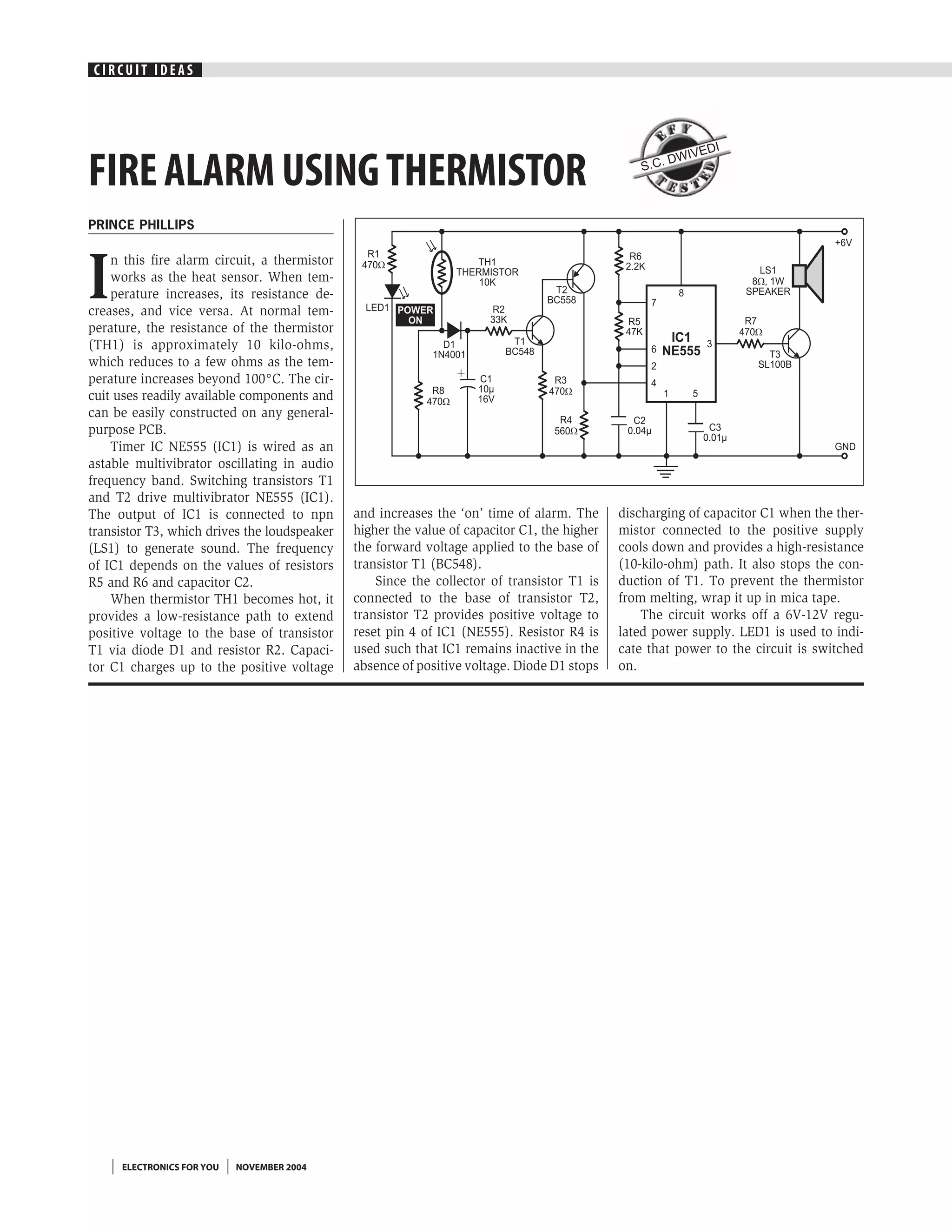
CIRCUIT IDEAS


                                                                                                            I
                                                                                                         VED
                                                                                                      DWI
FIRE ALARM USING THERMISTOR                                                                      S.C.


PRINCE PHILLIPS


I
    n this fire alarm circuit, a thermistor
    works as the heat sensor. When tem-
    perature increases, its resistance de-
creases, and vice versa. At normal tem-
perature, the resistance of the thermistor
(TH1) is approximately 10 kilo-ohms,
which reduces to a few ohms as the tem-
perature increases beyond 100°C. The cir-
cuit uses readily available components and
can be easily constructed on any general-
purpose PCB.
    Timer IC NE555 (IC1) is wired as an
astable multivibrator oscillating in audio
frequency band. Switching transistors T1
and T2 drive multivibrator NE555 (IC1).
The output of IC1 is connected to npn         and increases the ‘on’ time of alarm. The      discharging of capacitor C1 when the ther-
transistor T3, which drives the loudspeaker   higher the value of capacitor C1, the higher   mistor connected to the positive supply
(LS1) to generate sound. The frequency        the forward voltage applied to the base of     cools down and provides a high-resistance
of IC1 depends on the values of resistors     transistor T1 (BC548).                         (10-kilo-ohm) path. It also stops the con-
R5 and R6 and capacitor C2.                       Since the collector of transistor T1 is    duction of T1. To prevent the thermistor
    When thermistor TH1 becomes hot, it       connected to the base of transistor T2,        from melting, wrap it up in mica tape.
provides a low-resistance path to extend      transistor T2 provides positive voltage to         The circuit works off a 6V-12V regu-
positive voltage to the base of transistor    reset pin 4 of IC1 (NE555). Resistor R4 is     lated power supply. LED1 is used to indi-
T1 via diode D1 and resistor R2. Capaci-      used such that IC1 remains inactive in the     cate that power to the circuit is switched
tor C1 charges up to the positive voltage     absence of positive voltage. Diode D1 stops    on.


     ELECTRONICS FOR YOU   NOVEMBER 2004

Fire alarm using thermistor

  • 1.
    CIRCUIT IDEAS I VED DWI FIRE ALARM USING THERMISTOR S.C. PRINCE PHILLIPS I n this fire alarm circuit, a thermistor works as the heat sensor. When tem- perature increases, its resistance de- creases, and vice versa. At normal tem- perature, the resistance of the thermistor (TH1) is approximately 10 kilo-ohms, which reduces to a few ohms as the tem- perature increases beyond 100°C. The cir- cuit uses readily available components and can be easily constructed on any general- purpose PCB. Timer IC NE555 (IC1) is wired as an astable multivibrator oscillating in audio frequency band. Switching transistors T1 and T2 drive multivibrator NE555 (IC1). The output of IC1 is connected to npn and increases the ‘on’ time of alarm. The discharging of capacitor C1 when the ther- transistor T3, which drives the loudspeaker higher the value of capacitor C1, the higher mistor connected to the positive supply (LS1) to generate sound. The frequency the forward voltage applied to the base of cools down and provides a high-resistance of IC1 depends on the values of resistors transistor T1 (BC548). (10-kilo-ohm) path. It also stops the con- R5 and R6 and capacitor C2. Since the collector of transistor T1 is duction of T1. To prevent the thermistor When thermistor TH1 becomes hot, it connected to the base of transistor T2, from melting, wrap it up in mica tape. provides a low-resistance path to extend transistor T2 provides positive voltage to The circuit works off a 6V-12V regu- positive voltage to the base of transistor reset pin 4 of IC1 (NE555). Resistor R4 is lated power supply. LED1 is used to indi- T1 via diode D1 and resistor R2. Capaci- used such that IC1 remains inactive in the cate that power to the circuit is switched tor C1 charges up to the positive voltage absence of positive voltage. Diode D1 stops on. ELECTRONICS FOR YOU NOVEMBER 2004