This circuit allows appliances to be turned on or off automatically using a timer or by clapping. The timer uses a digital clock circuit to trigger power to appliances at preset times. It can also be activated by clapping, using a microphone and transistor amplifier to generate a voltage pulse. When the clock or clap signal is received, it toggles a bistable flip-flop circuit controlling power. This provides a simple, inexpensive way to remotely control appliances without touching the unit.
Auto Control for Three Phase Induction Motor� is one of the advancements in Electrical Machines. This paper focuses on several advancements that overcome the shortcomings,such as line dropout,single phasing,ove rload damage and reverse phasing present in the existing systems using 3 - Phase Motors. The 3 - Phase Motor controller circuit presented here is fully IC based,which is designed to work in difficult environmental conditions. This drive integrates several fac ilities with built - in protection for current sensing,overload control,under/over frequency cut - off along with auto - starter and off - timer. This controller is possesses major parts viz.,phase sequence checker,auto - starter and current sensing circuit,mot or on - off timer and power supply circuit .
Digital timer switches are utilized to control the task of electrical gadgets dependent on a customized timetable. This undertaking portrays a programmable digital timer dependent on the PIC16F628A microcontroller that can be customized to plan the on and off activity of an electrical apparatus. The apparatus is controlled through a hand-off switch. This clock change enables you to set both on and off time. That implies, you can program when would you like to turn the gadget on and for to what extent you need it to be stayed on. The greatest time interim that you can set for on and off activity is 99 hours and 59 minutes. The task gives an intuitive UI utilizing a 16×2 character LCD alongside 4 push catches.
The slides explain how a voltage inverter can be made using 555 timer in astable mode.
It contains a clear description of the working of the 555 timer and hence the voltage inverter.
Part of Lecture series on EE321N, Power Electronics-I delivered by me during Fifth Semester of B.Tech. Electrical Engg., 2012
Z H College of Engg. & Technology, Aligarh Muslim University, Aligarh
Please comment and feel free to ask anything related. Thanks!
This is a short presentation of two types of my inventions (patents):
-method of current sensing in three phase bridge;
-interleave power supply with zero emf detection.
Power point presentation on logical families.
A good presentation cover all topics.
For any other type of ppt's or pdf's to be created on demand contact -dhawalm8@gmail.com
mob. no-7023419969
Catalog Osung, Catalog,
Catalog Thiết Bị Điện Osung, Catalog Thiết Bị Điện,
Catalog Biến Tần Osung, Catalog Điện Công Nghiệp,
http://dienhathe.com,
Chi tiết các sản phẩm khác của Osung tại https://dienhathe.com
Xem thêm các Catalog khác của Osung tại https://dienhathe.info
Để nhận báo giá sản phẩm Osung vui lòng gọi: 0907.764.966
Functional block, characteristics of 555 Timer and its PWM application – IC-566 voltage controlled oscillator IC; 565-phase locked loop IC, AD633 Analog multiplier ICs.
We are going to make a simple clap switch, how to switch on the lights, for a while, with a single clap. This will help us to search some objects in the dark, when you are watching TV or lying on bed etc.
Components
• 1-mic
• BC547 two
• IC LM358
• Resistor 1k, 10k, 100k
• 7805 voltage regulator
• LED
• Buzzer
• 555 timer IC
• 100nf, 10uf capacitor
• Step down transformer.
This anti-sleep alarm keeps you awake. This circuit keeps you vigilant by sounding intermittent beeps and emitting flashing light so as to remind you that you are not on the bed but driving a vehicle. It works only at night due to the control of a light-dependent resistor (LDR) based switch.
Part of Lecture series on EE321N, Power Electronics-I delivered by me during Fifth Semester of B.Tech. Electrical Engg., 2012
Z H College of Engg. & Technology, Aligarh Muslim University, Aligarh
Please comment and feel free to ask anything related. Thanks!
Linear Integrated Circuits and Its Applications Unit-V Special ICsSatheeshCS2
Linear Integrated Circuits and Its Applications
Unit-V Special ICs
Mr. C.S.SATHEESH, M.E.(Control Systems),
Assistant Professor, Department of EEE, Muthayammal Engineering College, (Autonomous) Namakkal (Dt), Rasipuram – 637408
1. CIRCUIT
IDEAS
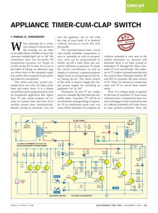
APPLIANCE TIMER-CUM-CLAP SWITCH
PANKAJ D. CHOUDHURY turn the appliance ‘on’ or ‘off’ with
the clap of your hand, if so desired,
IVEDI
S.C. DW
W
hen planning for a week- without having to touch the unit
end outing to return late in physically.
the evening, we are often The transistor-based timer circuit
in an ambivalence whether to leave the uses readily available components, is
staircase/outside light ‘on’ or ‘off.’ We easy to assemble as well as inexpen- collector potential is very near to the
sometimes miss our favourite TV sive, and can be programmed to emitter potential, i.e., ground, and
programme because we forget to switch on/off a load from one sec- therefore there is no base current to
switch on the TV in time. If we are in ond to 100 hours in advance. To make transistors T7 through R6. Thus, tran-
the habit of taking an afternoon nap, the circuit cost-effective as well as sistor T7 is in cut-off state. The collec-
we either turn on the mosquito repel- simple to construct, a general-purpose tor of T7 is above ground potential and
lent earlier than required or get up be- digital clock is incorporated as the ba- the current flows through resistors R7
ing bitten by mosquitoes. sic timing device. The alarm output and R13 to maintain the base current
The timer-cum-clap switch pre- of the clock is used to toggle the out- of T6. Thus, T6 remains in conduction
sented here can solve all these prob- put power supply for switching an state and T7 in cut-off state indefi-
lems and many more. It is a simple appliance ‘on’ or ‘off.’ nitely.
circuit that can be programmed to turn Transistors T6 and T7 are config- Now, if a voltage pulse is applied
on household appliances like lights, ured as a bistable flip-flop that has two to the base of transistor T7 from some
fans, TV sets, music systems, etc ex- stable states. Transistor T7 will be in external source, a momentary base cur-
actly at a preset time and turn off at cut-off mode corresponding to transis- rent will trigger it into conduction and
another preset time automatically, tor T6 in conduction mode, and vice its collector potential will come down
thereby saving on electricity. You can versa. When transistor T6 conducts, its to near ground potential. Thus, the
WWW.EFYMAG.COM ELECTRONICS FOR YOU • NOVEMBER 2006 • 99
2. CIRCUIT
IDEAS
current flowing through resistor R13 emitter of T5 and the output changes This simple circuit can be as-
will pass through the collector of T7 over. sembled on a general-purpose PCB.
and there will be no current through When clap switch is not required, The clock, battery, switches, relay,
R7, making T6 go into cut-off state S2 can be turned off. S3 is the reset transformer, etc are wired with the
and thereby raising the collector po- switch (push-to-on type), which is PCB (not shown in the circuit). A plas-
tential of T6 to some positive value. used to toggle the output between tic switchboard (available in electrical
This, in turn, will keep T7 conduct- ‘on’ and ‘off’ states. R10-C7 and R8- shops) can be used as the cabinet for
ing. Now the base current of T7 will C6 are parallel paths to R7 and R6 assembling the unit. Holes can be
pass through resistors R14 and R6. for quick switchover of the bistable drilled easily on the plastic cabinet.
This state will sustain until some ex- latch. House the PCB, transformer, relay, etc
ternal voltage is applied to the base Two AA-size batteries supply 3V inside the cabinet. Fix the plug socket,
of T6. DC to the clock and maintain a posi- switches and external connector on the
The external voltage pulse (for tive voltage to the collectors of T6 rear side of the cabinet. Indicator LEDs
switching) is taken from two sources: and T7 through diode D7. This keeps (fixed on LED sockets) on the front
the alarm output of a clock or the the circuit active during power fail- panel show ‘on’ or ‘off’ condition of
sound picked up by condenser micro- ures also. A step-down transformer the output plug.
phone ‘M’ after proper amplification supplies 12V DC to the relay coil and Glue the condenser microphone in-
by transistors T1, T2 and T3. sound amplifier section. Diodes D5 side the front or side wall with small
Since most of the digital clocks and D6 are rectifier diodes and C5 is holes drilled in front of it to receive
give out negative pulses to the buzzer the ripple filter capacitor. Diode D4 external sound. The battery chamber
(whose other end is directly connected prevents the 3V battery from drain- housing two pencil cells can be fixed
to the positive terminal of the bat- ing out into the rest of the circuit. inside the cabinet or on the rear of the
tery), a reverse diode (D8) and a pnp The digital clock is a commonly cabinet as per convenience. The clock
transistor (T10) are used at this stage. available digital calendar with at least is glued on top of the cabinet. Before
The negative pulses are rectified by one alarm setting and one countdown fixing the clock on the cabinet, open it
D8 and filtered by C9 to supply a timer setting. The digital calendar, be- carefully to disconnect its piezoelec-
steady base current of T10. Otherwise, ing cheap, keeps the total cost of the tric buzzer. The terminal that shows
the output will become noisy because project low and allows for precise set- pulsating voltage during an alarm op-
of the pulsating nature of the alarm. tings of the alarm times. The alarm eration (detected with a multimeter)
(If the clock gives out positive pulses, can be set 24 hours in advance, while is connected to the base of T10 through
T10 can be replaced with an npn a second alarm can be selected in the D8 and R19. The internal battery is re-
transistor like BC547. Diode D8 has countdown timer mode, which allows placed and the terminals are connected
to be reversed and R18 has to be con- for setting of the time 100 hours to the external battery chamber with
nected between the base of T10 and (99:59:59 hours to be precise) in ad- proper polarity.
ground.) vance. Availability of more than one The operation of the circuit can be
The external voltage pulse is fed at alarm setting in the clock will give divided into two parts: clap mode and
the common emitter of transistors T4 the added advantage of setting mul- timer mode.
and T5 through capacitor C8. When tiple switching times. The timer can be put in clap mode
the alarm starts (sending negative volt- Instead of the digital calendar, any by turning on the clap switch (S2). The
age pulses), capacitor C9 discharges other digital clock or battery-operated connected appliance can now be
through D8 and, at the same time, quartz clock (with alarm) can also be turned on/off by clapping with an au-
charges through R19, thus triggering used as the basic timing device, dible intensity. The clock timer will
the base current of T10. The emitter though the alarm time setting is less function as usual in this mode.
current of T10 charges capacitor C8, precise in case of the latter. Instead While clapping, leave a gap of a
which passes through the emitter of of one clock, multiple clocks can be few seconds between two successive
either T4 or T5 depending on their wired by connecting diodes parallel claps. Thus, the gadget will show
bias. to D8. better response because it has been
When T6 is conducting, T4 is for- Note that once set in the clock designed to consider two overlapping
ward biased and the voltage pulse is mode, the alarm operates daily at the claps as one, ignoring the second
fed at the base of T7, bringing T7 into same time. But in the countdown one.
conduction and T6 into cut-off mode. mode, it operates only once. So if an For timer mode, switch S2 is turned
This makes T5 forward-biased and T4 appliance is to be turned on and off off. The alarm is set at the time when
reverse-biased. The next voltage pulse, daily at the same time without human switchover is required. The second
either through T10, D1 or D2 corre- intervention, at least two digital clocks switchover time can be set in the
sponding to the clock alarm, clap have to be wired (if the clock does not countdown timer. For that, the time
sound or operation of the reset switch, have two alarm settings apart from the difference between the present time
sends a base current of T6 through the countdown timer). and the time at which switching is re-
100 • NOVEMBER 2006 • ELECTRONICS FOR YOU WWW.EFYMAG.COM
3. CIRCUIT
IDEAS
quired is calculated and this time is reset switch S3. off) to allow for the first alarm to
set in the countdown timer. When set- While setting the alarm, ensure a subside completely. Otherwise, the
ting is done, set the output plug as delay of at least three minutes be- unit may malfunction (ignore the
‘on’ or ‘off’ (as desired) by pressing tween two successive alarm times (on/ second alarm).
WWW.EFYMAG.COM ELECTRONICS FOR YOU • NOVEMBER 2006 • 101