Downloaded 2,143 times

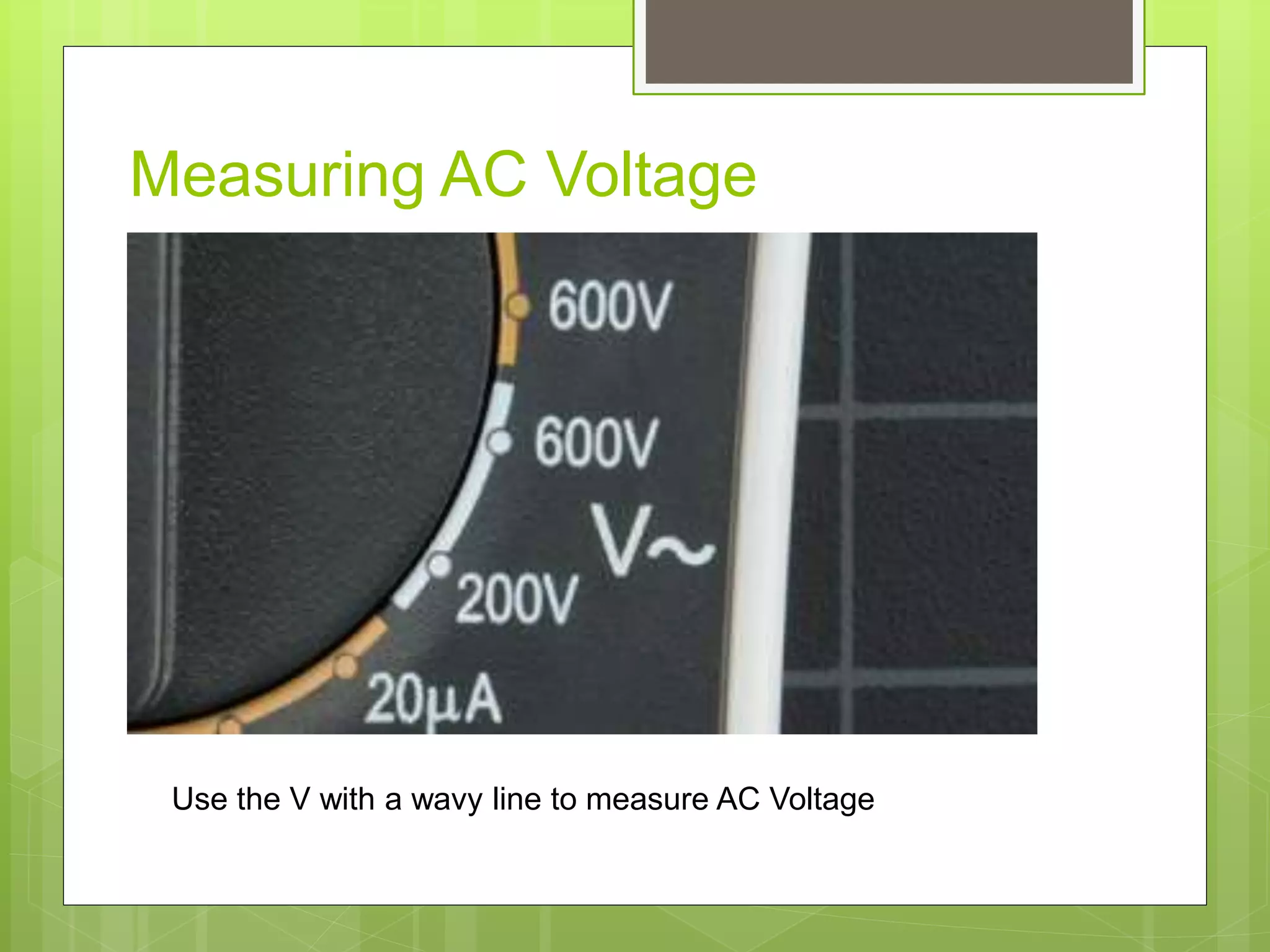

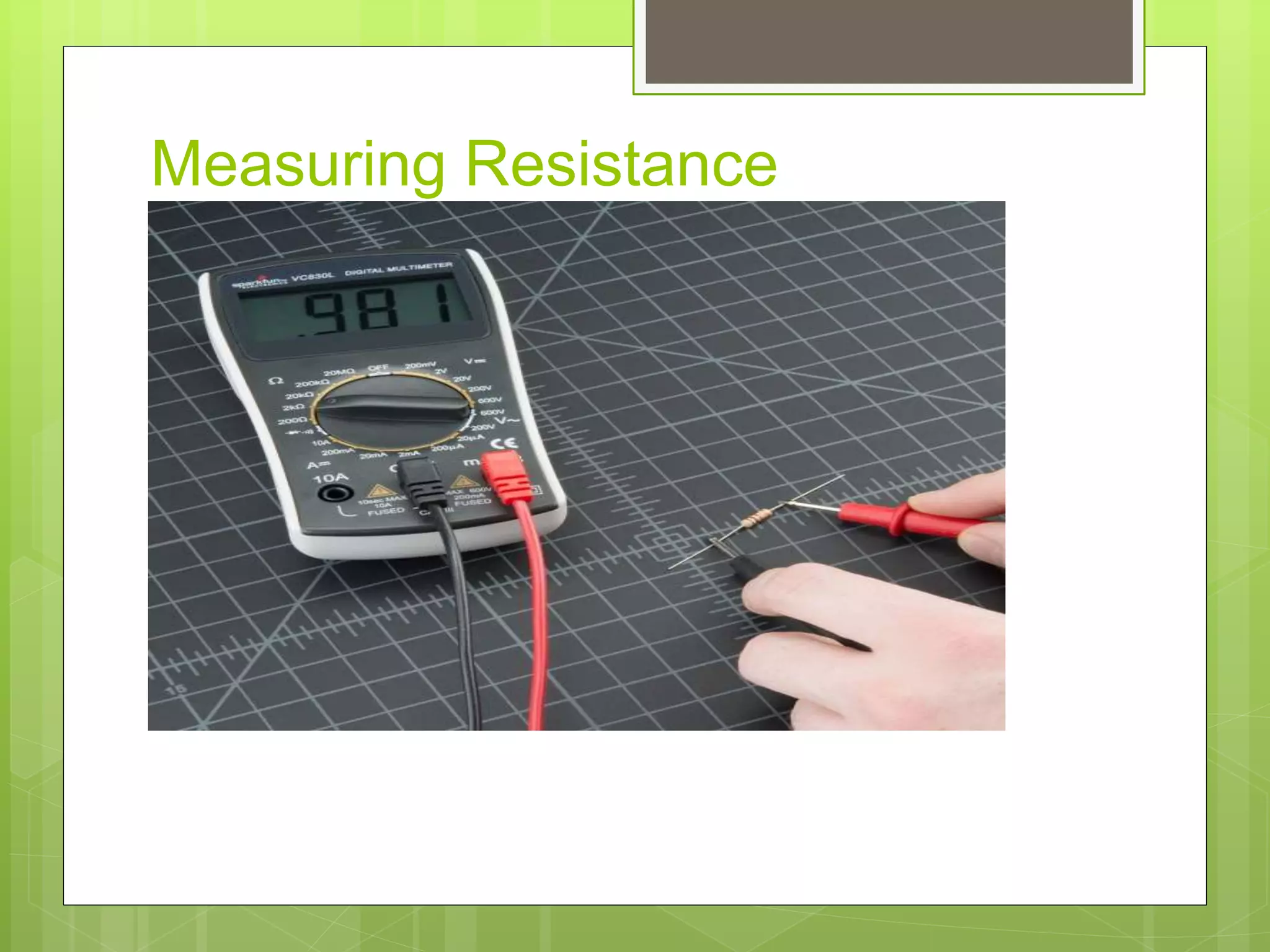


This document discusses different types of basic electrical measuring instruments. It describes absolute instruments, like tangent galvanometers, which directly measure electrical quantities without needing calibration. Secondary instruments require calibration against a standard, examples being multimeters, clamp meters, ammeters and voltmeters. Multimeters are described in detail, including their display, selection knob and ports. The document explains how to use a multimeter to measure AC voltage, DC voltage, resistance, current and test continuity. Clamp meters and the working of ammeters and voltmeters are also briefly covered.


![ELECTRICAL MEASUREMENT & MEASURING INSTRUMENTS [Emmi- (NEE-302) -unit-1]](https://cdn.slidesharecdn.com/ss_thumbnails/emmi-nee-302-unit-1-170607090405-thumbnail.jpg?width=640&height=640&fit=bounds)


