Downloaded 283 times
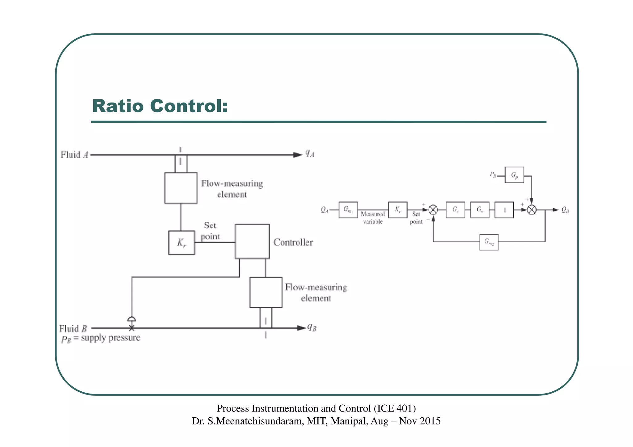
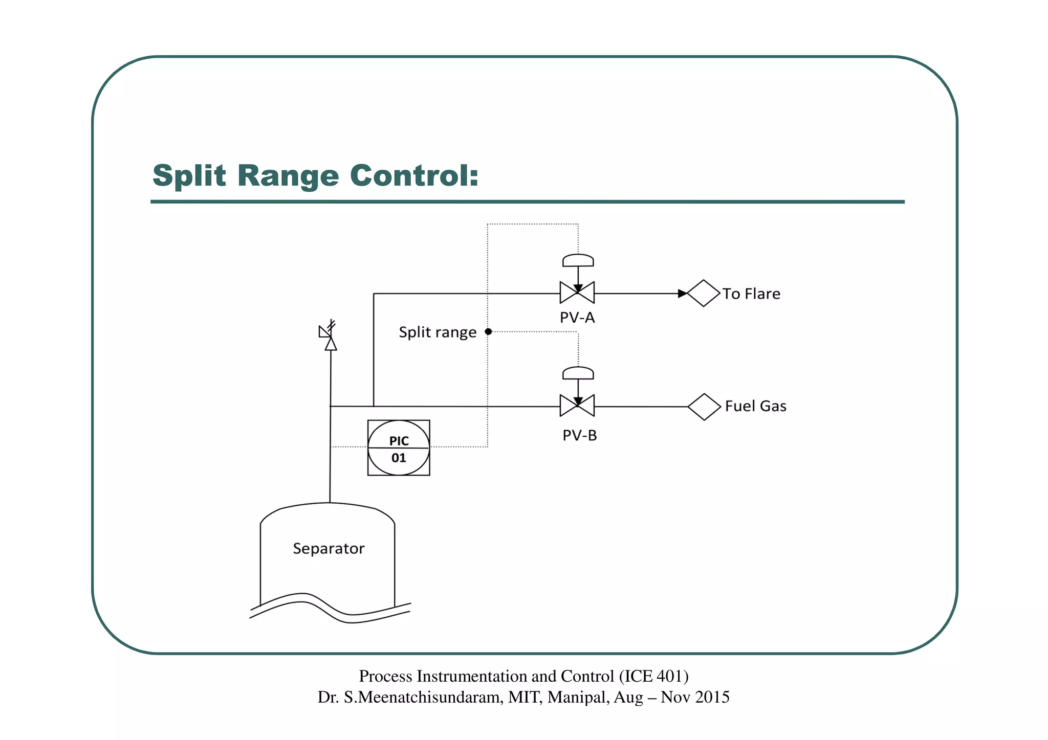
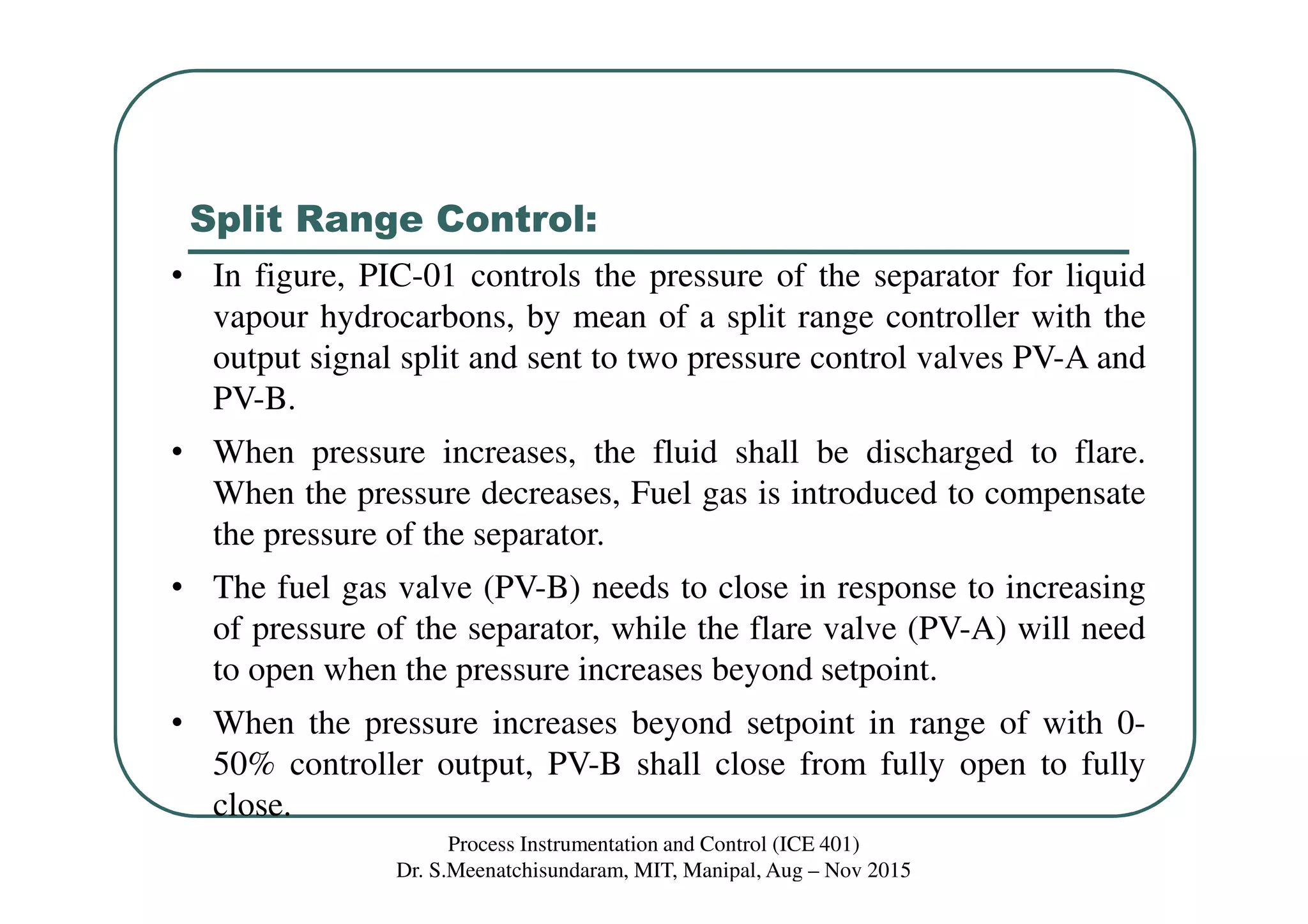
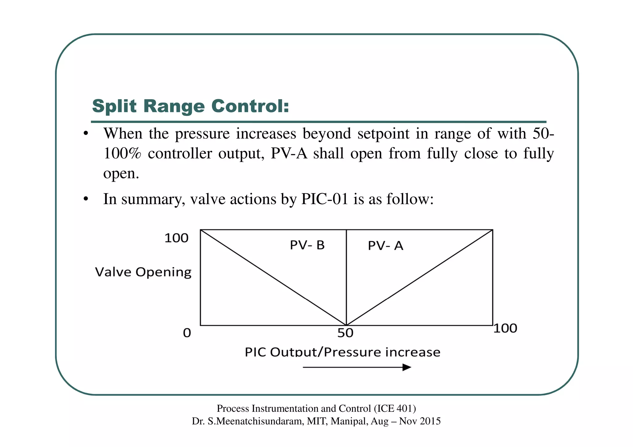
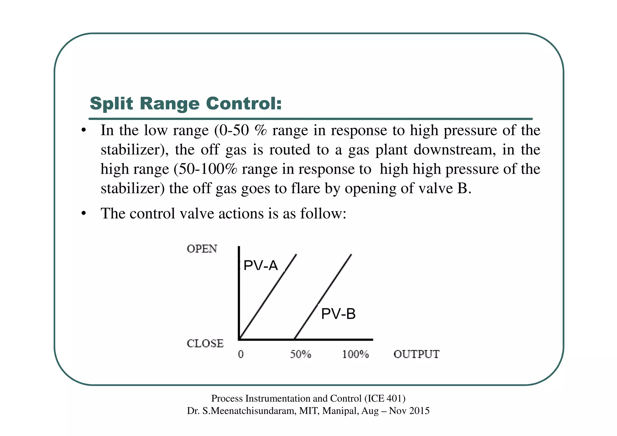
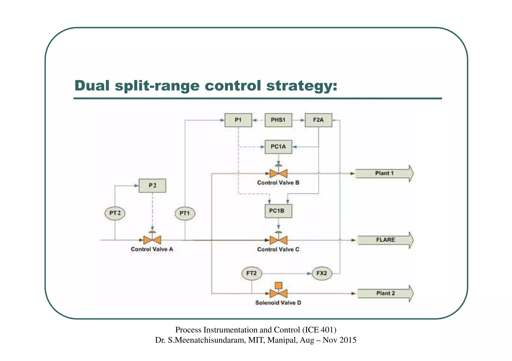

This document discusses ratio control and split range control strategies. It describes ratio control as using one uncontrolled stream to adjust the flow of a second stream to maintain a desired ratio between the two streams. Split range control involves splitting a controller's output between two or more control valves to sequence their operation over different ranges of the controller's output. Examples are given of using split range control to manage pressure in a separator by opening a flare valve or closing a fuel gas valve depending on the pressure level.