Downloaded 81 times
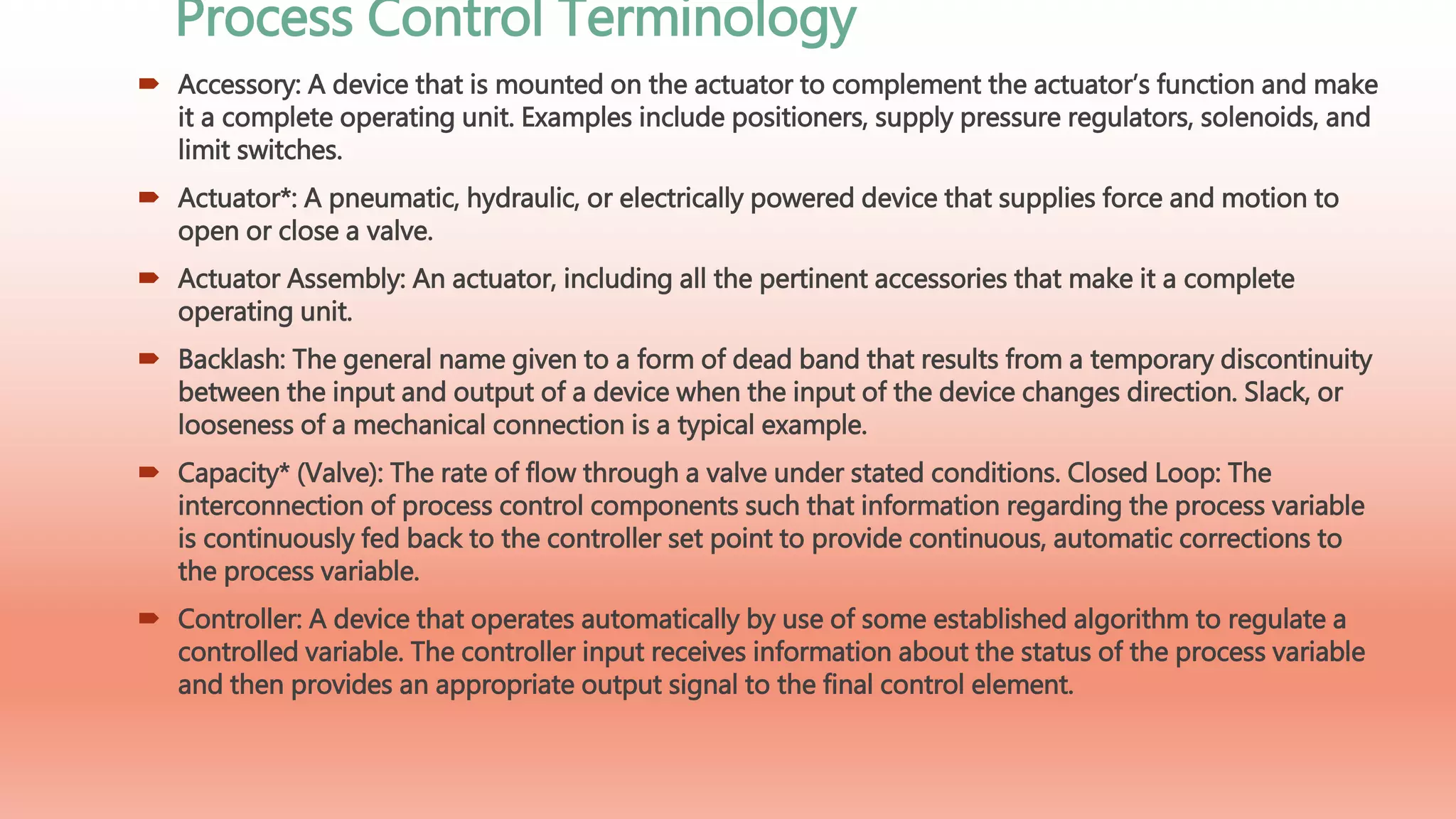


The document provides a comprehensive overview of control valves, detailing their function as critical components in process control systems to manage flow, pressure, temperature, and liquid levels. It discusses various terminologies and components associated with control valves, including actuator types, assembly components, and their operational characteristics. Additionally, it highlights the importance of maintaining control loops and describes different actuator designs such as diaphragm, piston, manual, and electric actuators.
Ashvani Kumar Shukla introduces the topic of control valves at Reliance.
The presentation covers control valve fundamentals, terminology, and functions.
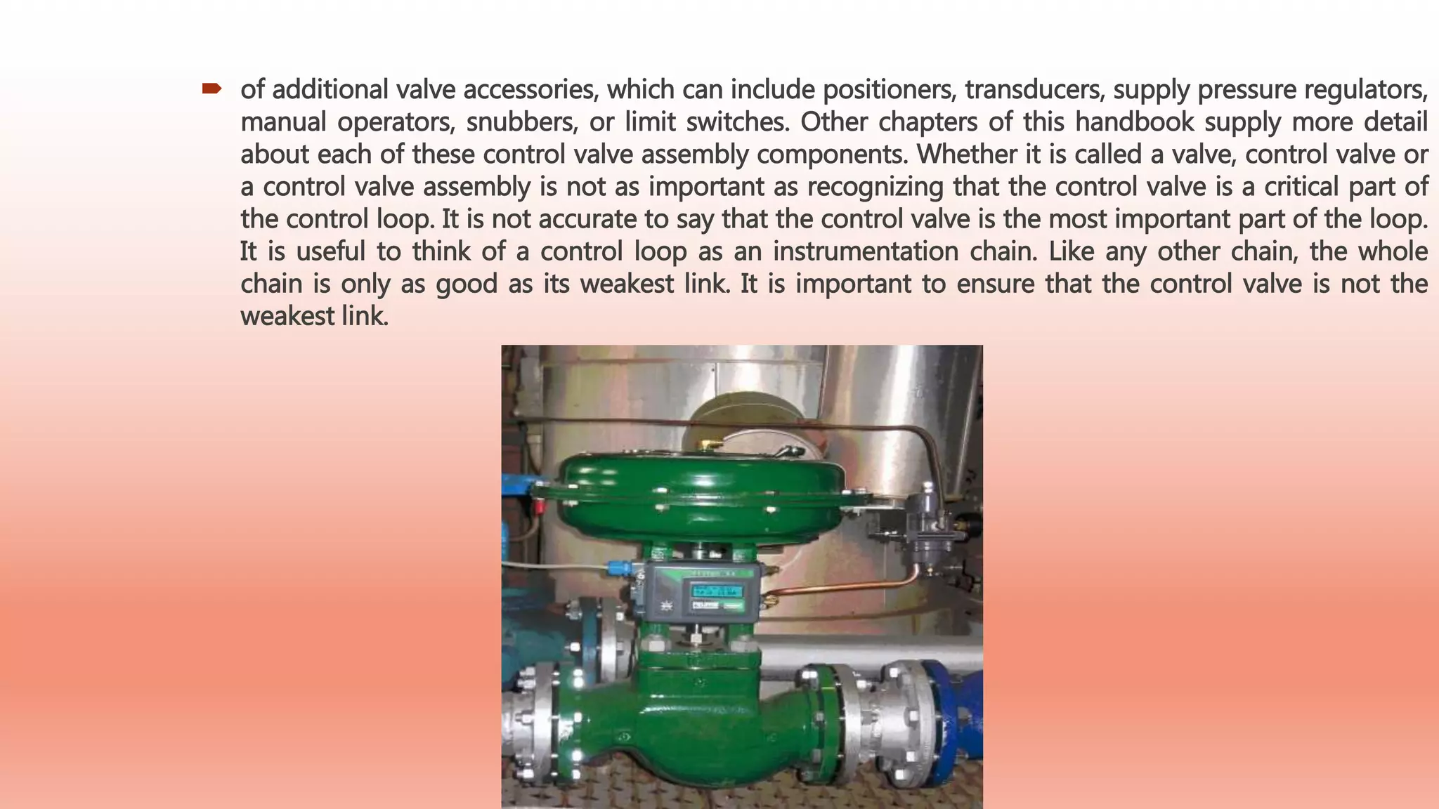
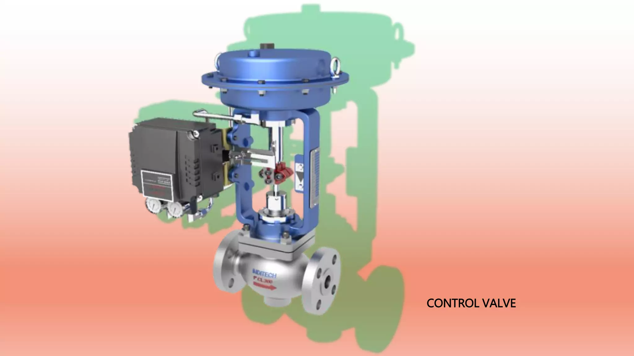
Control valves are essential for regulating flow, pressure, and temperature in process loops.
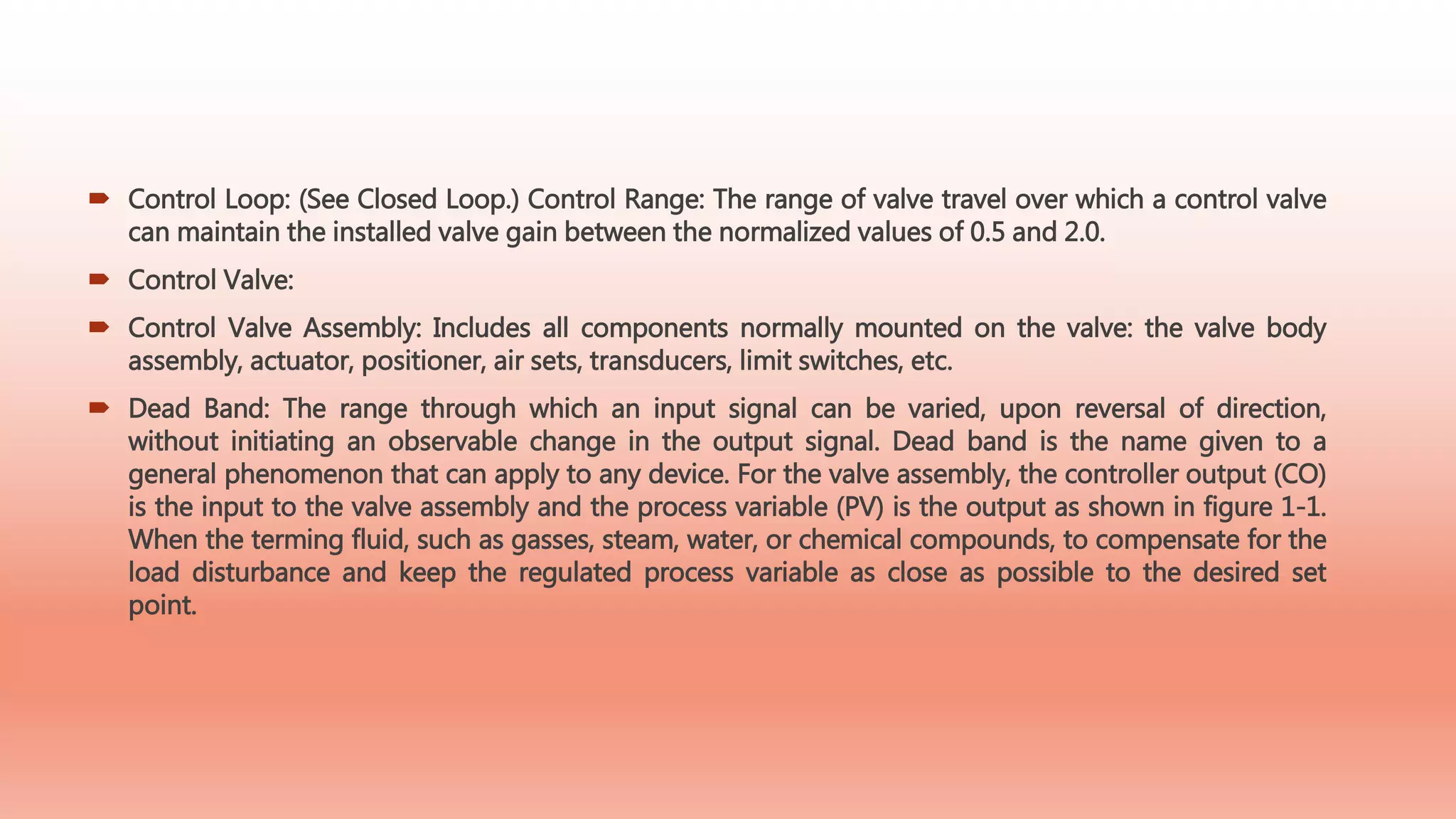
Defines critical terms such as actuator, control loop, and control valve assembly in process control.
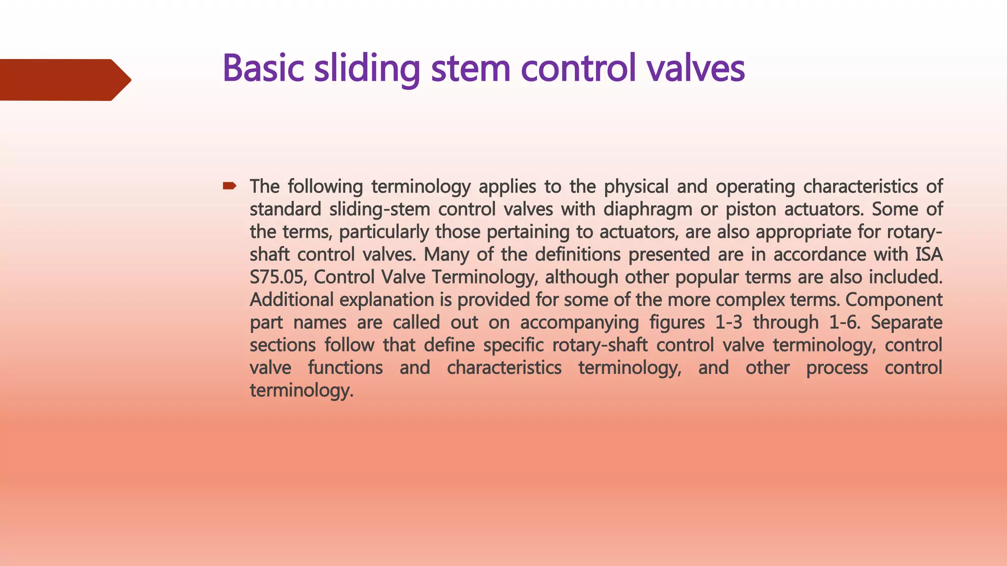
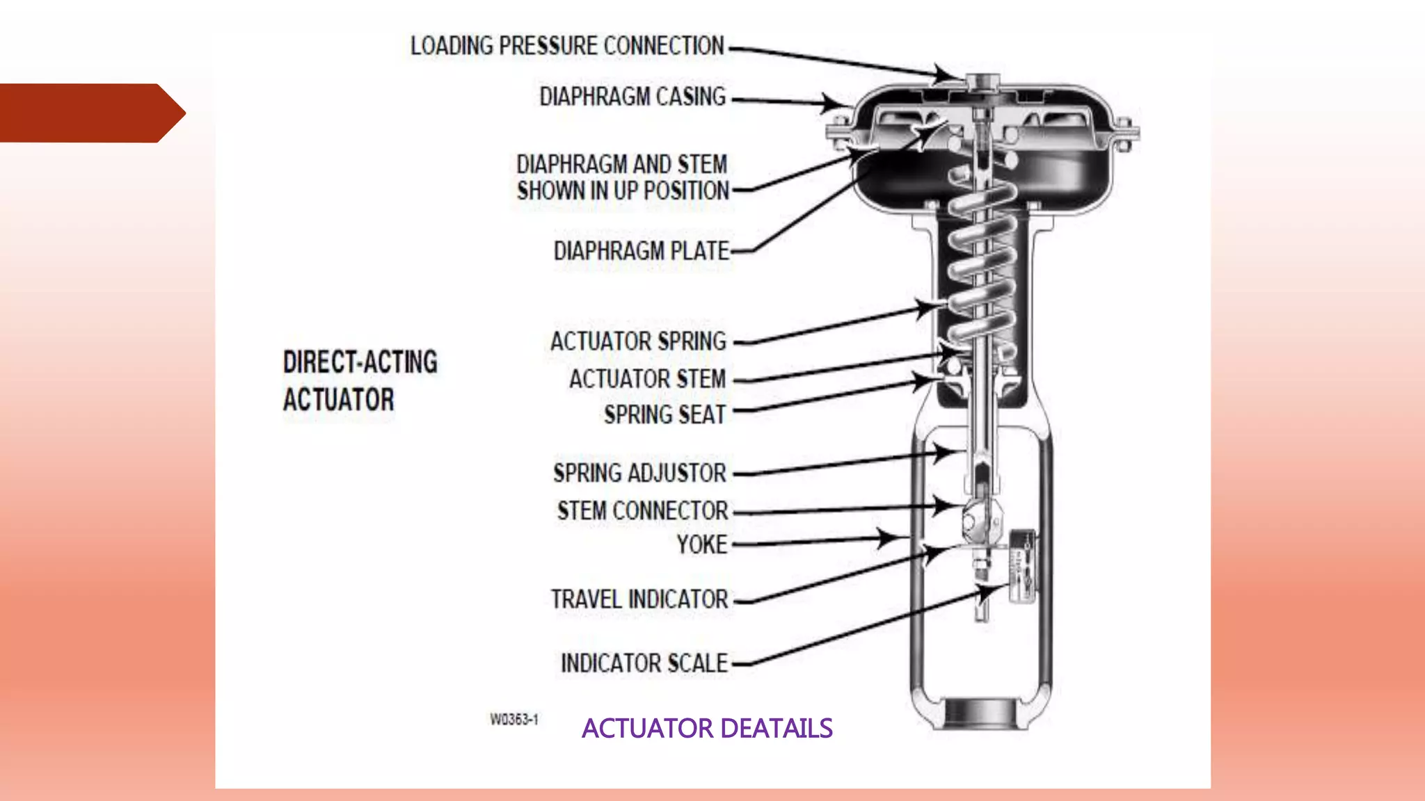
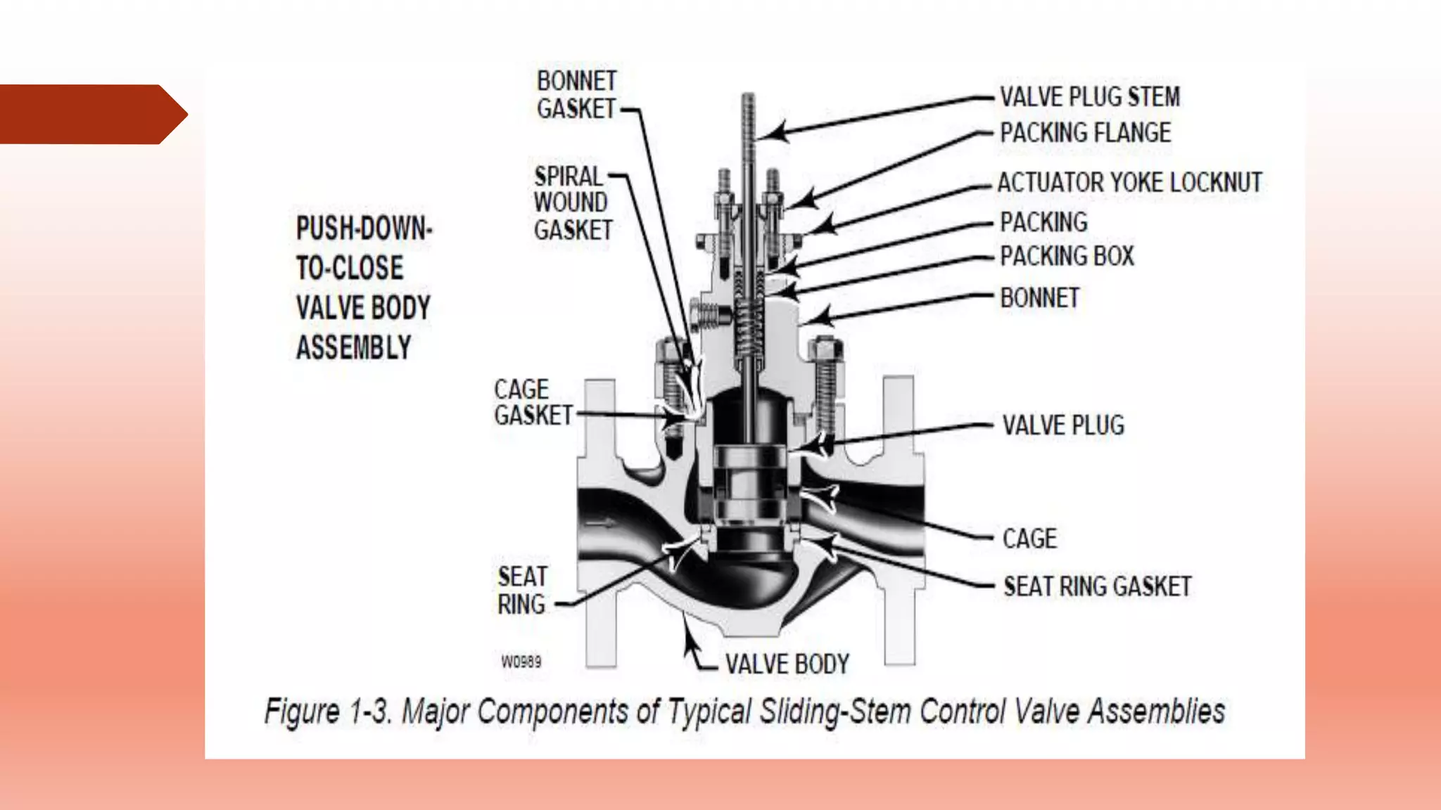
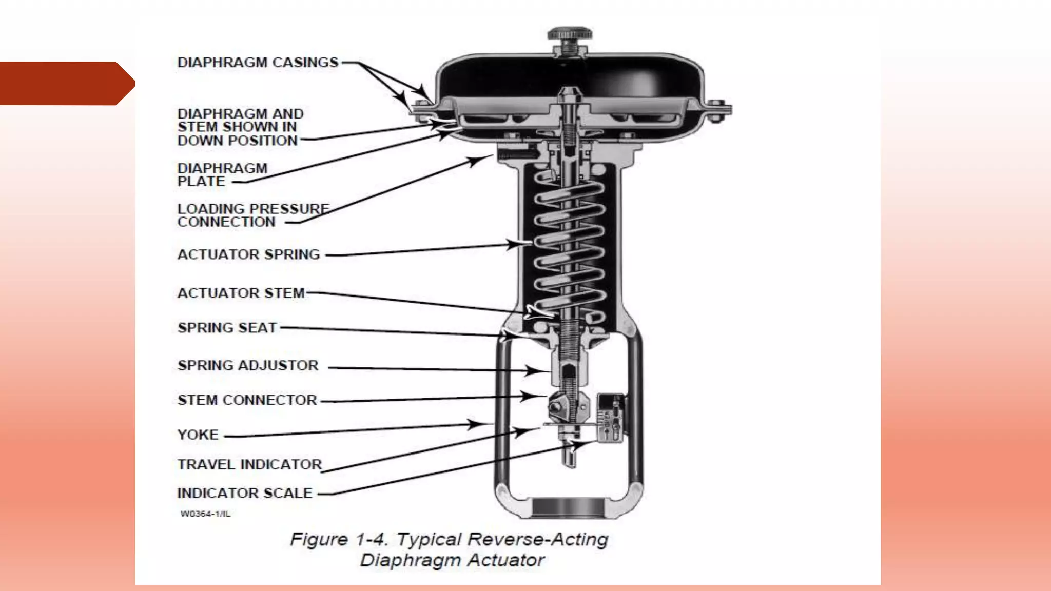
Terminology related to sliding-stem valves, including actuator components and their functions.
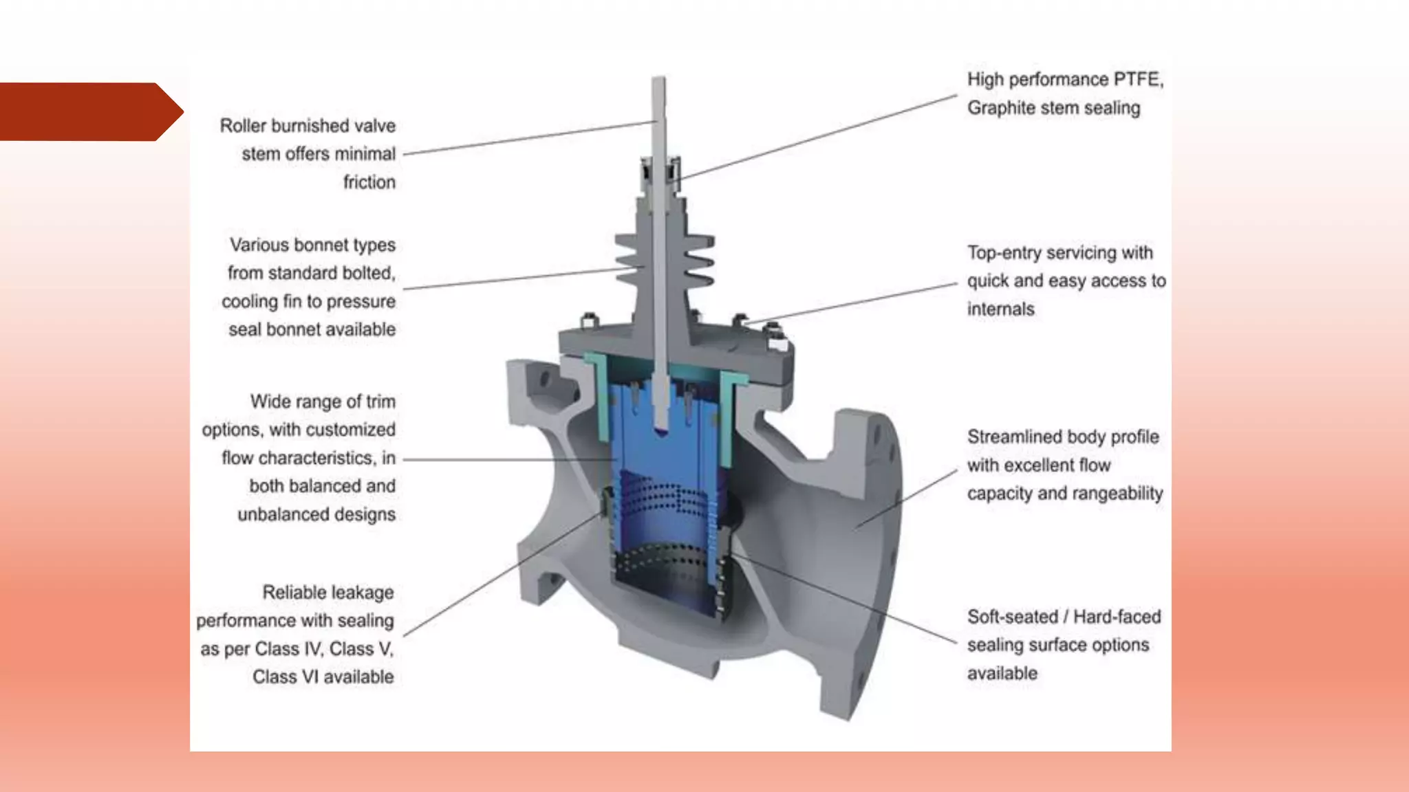
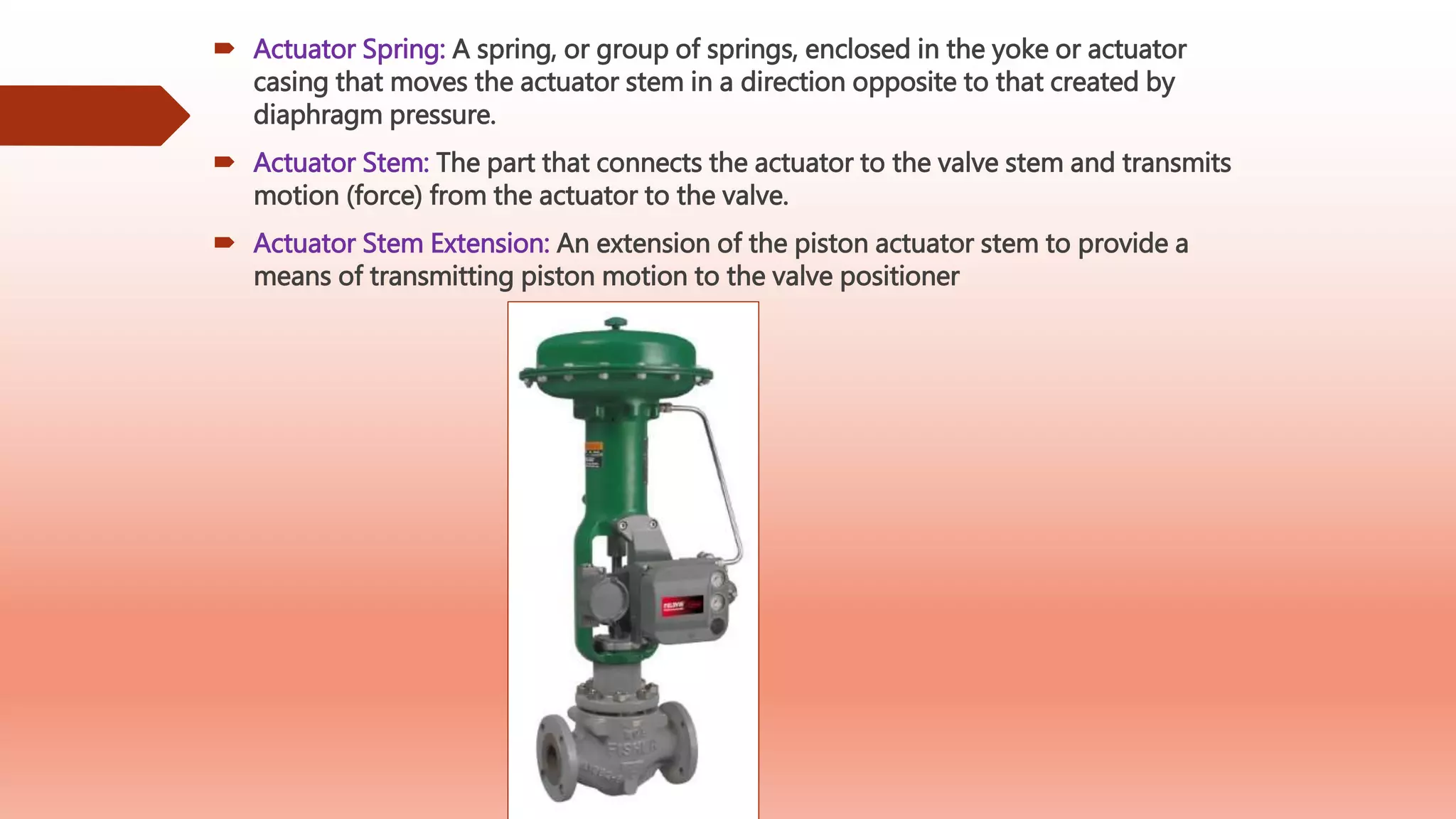
Detailed descriptions of valve components like bellows seal, bonnet assembly, and actuator designs.
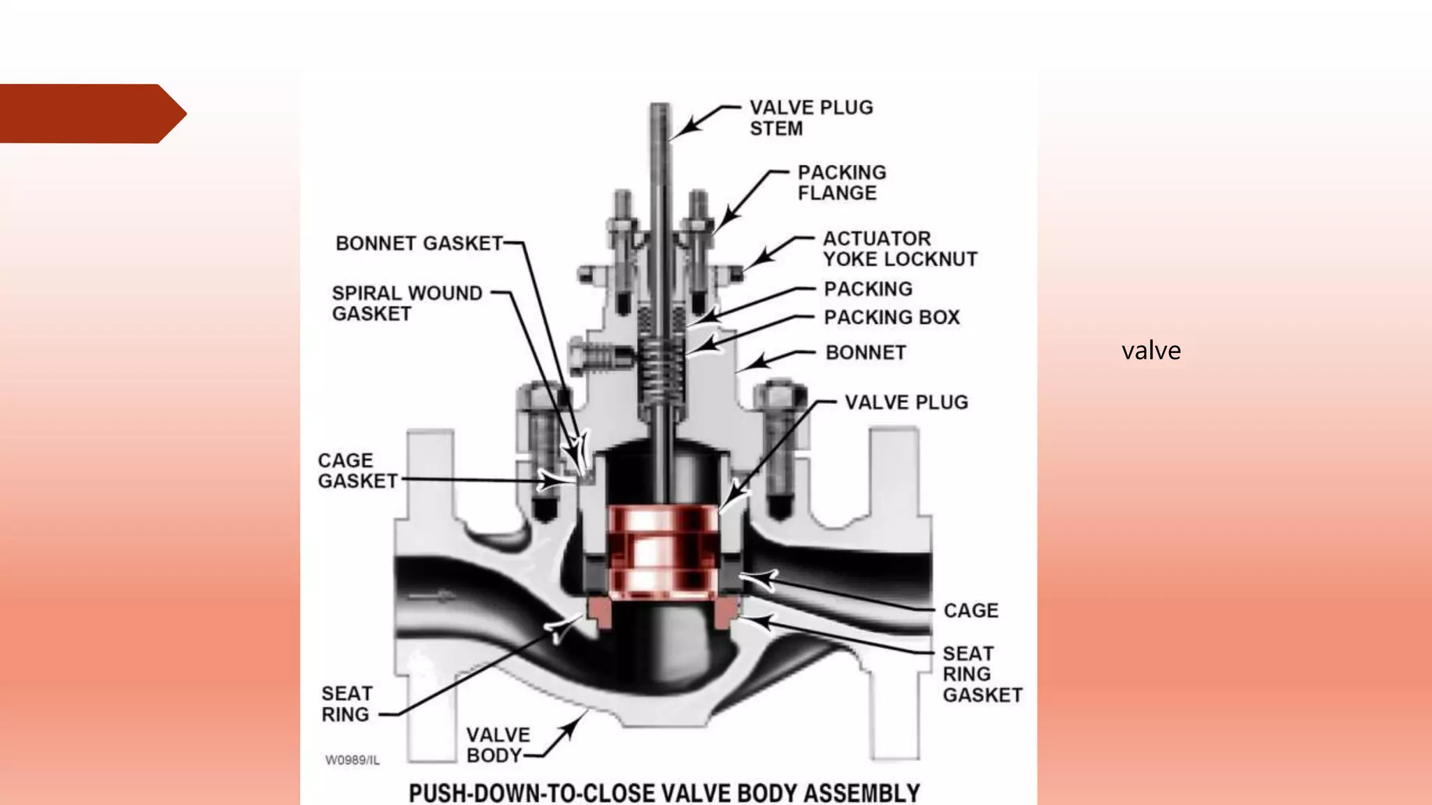
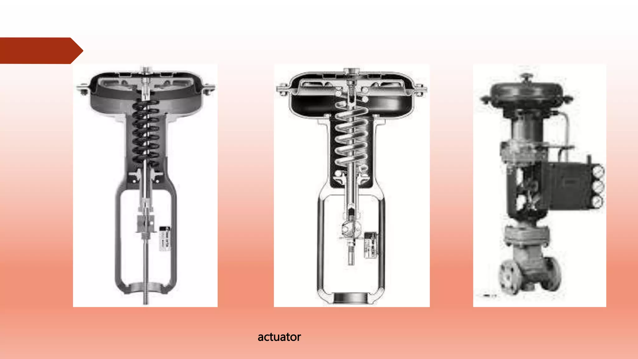
Pneumatic and manual actuators are discussed, including designs and their operational characteristics.
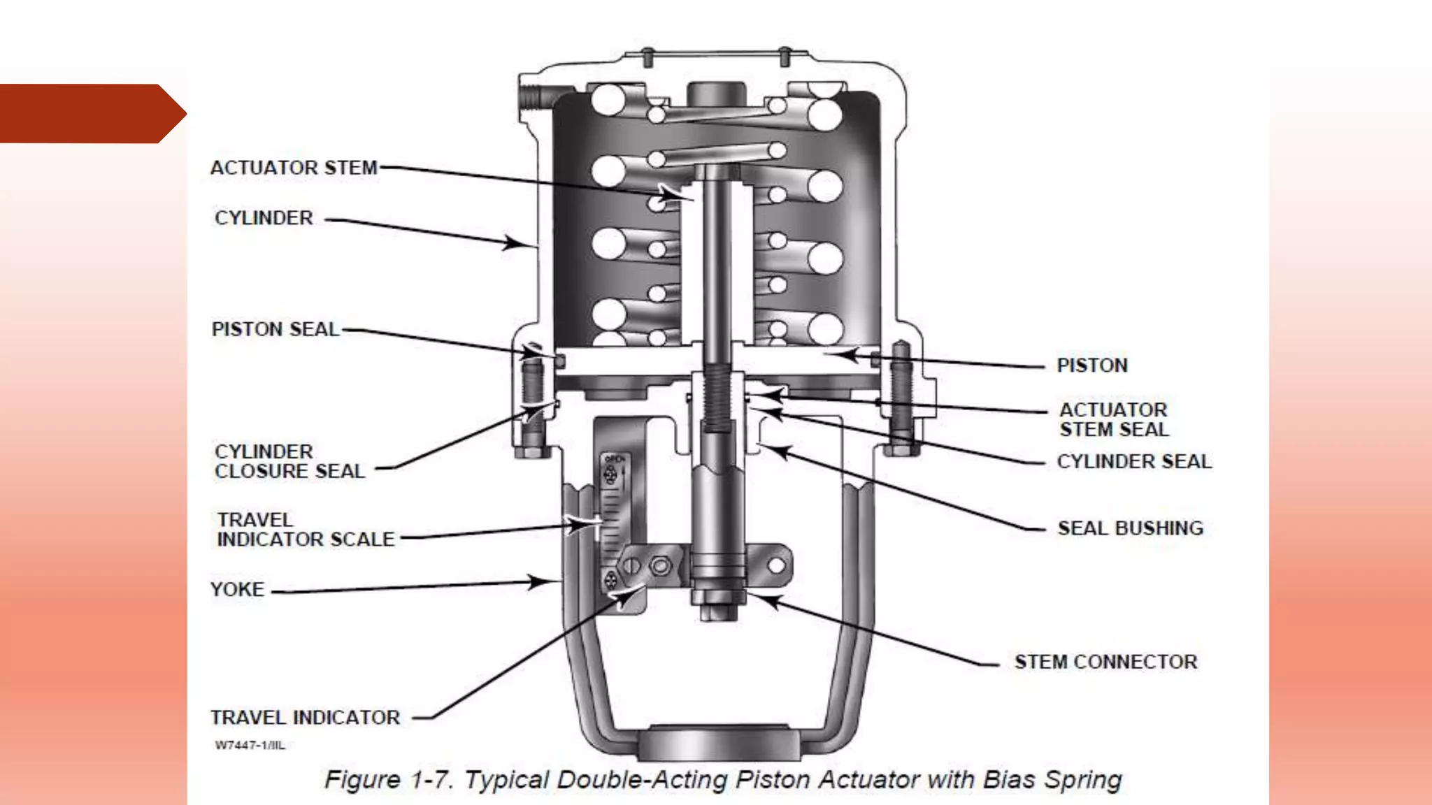
Descriptions of piston actuators and their configurations for valve operation and specialty uses.
Details on various actuator designs for rotary shaft valves, highlighting their control and cost dynamics.


