Downloaded 415 times

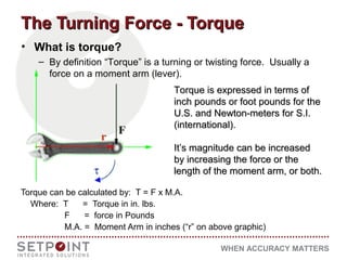
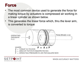
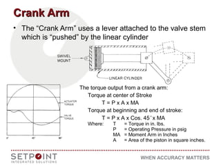
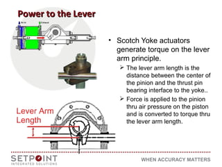
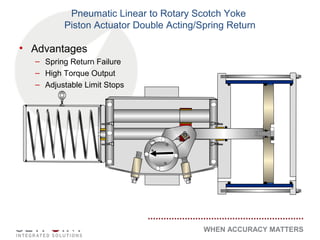
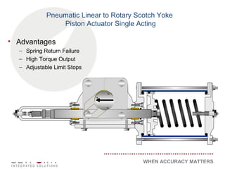
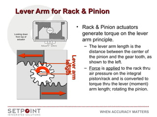
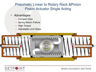
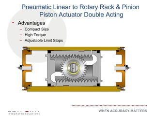
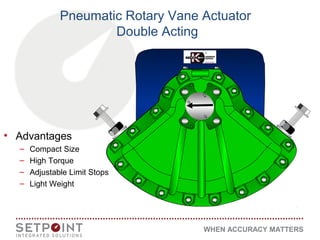
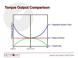
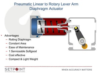
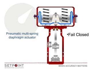
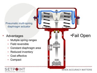
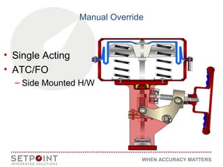
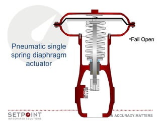
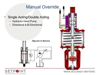
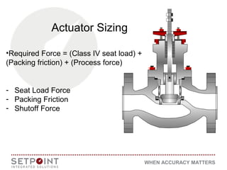
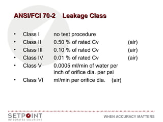
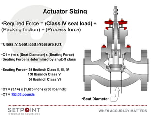
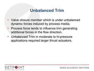
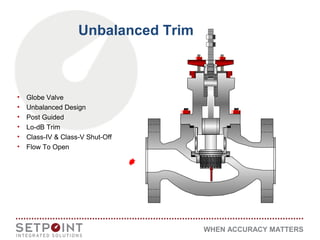
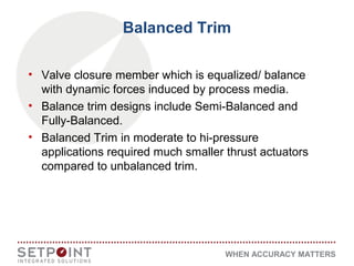
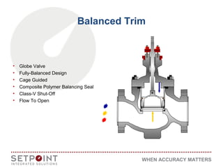
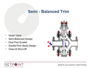


The document discusses pneumatics as a fluid power application using air, emphasizing its advantages such as lightweight and shock absorption. It details torque generation techniques using various actuator types like crank arm, rack & pinion, and scotch yoke, and provides insights on actuator sizing based on required forces and shut-off classes. The document also addresses the distinctions between balanced and unbalanced trim designs in valves, highlighting their implications for actuator selection in different pressure scenarios.


![[Deck] What's New in Spark-Iceberg Integration via DSV2.pptx](https://cdn.slidesharecdn.com/ss_thumbnails/deckwhatsnewinspark-icebergintegrationviadsv2-260210005337-25955b12-thumbnail.jpg?width=640&height=640&fit=bounds)


