Downloaded 509 times
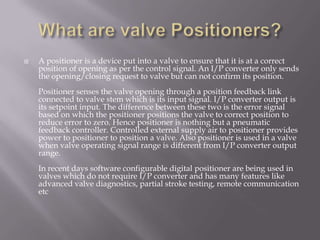

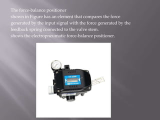
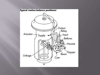
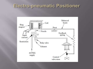
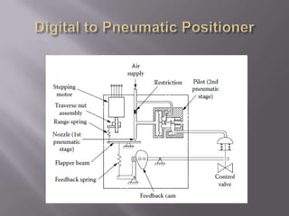


A positioner is a feedback controller device that ensures a control valve is in the correct position according to a control signal. It senses the valve's position and compares it to the signal from an I/P converter. Based on the difference or "error", it positions the valve to reduce the error to zero. Positioners improve the accuracy of a valve's response by reducing issues like friction, dynamic forces, and non-linearities. Modern digital positioners no longer require an I/P converter and offer additional features like diagnostics and partial stroke testing.


![3 Smart Positioner [Compatibility Mode] [Repaired].ppt](https://cdn.slidesharecdn.com/ss_thumbnails/3smartpositionercompatibilitymoderepaired-250502130500-85d558d9-thumbnail.jpg?width=640&height=640&fit=bounds)


