Downloaded 546 times
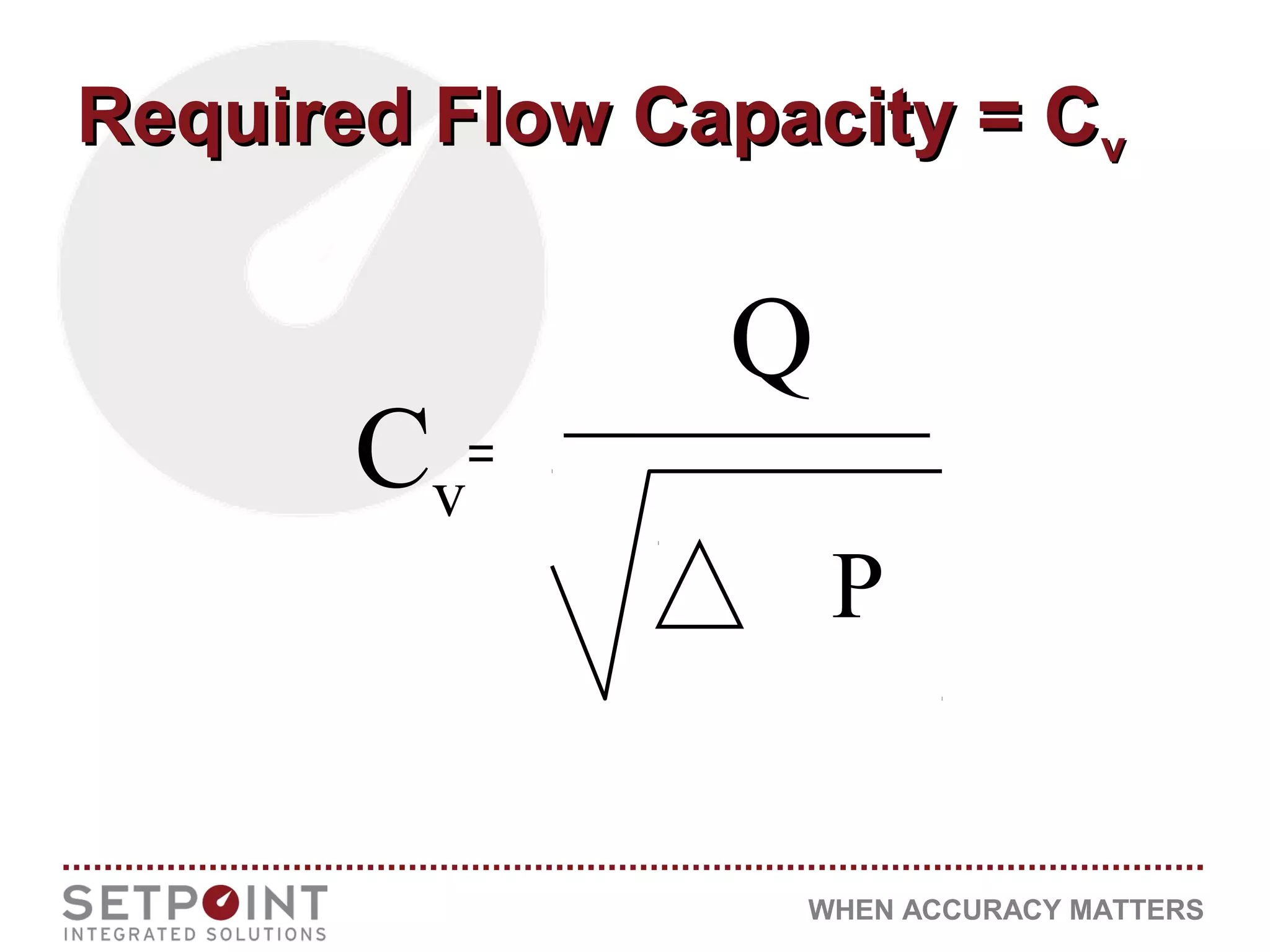
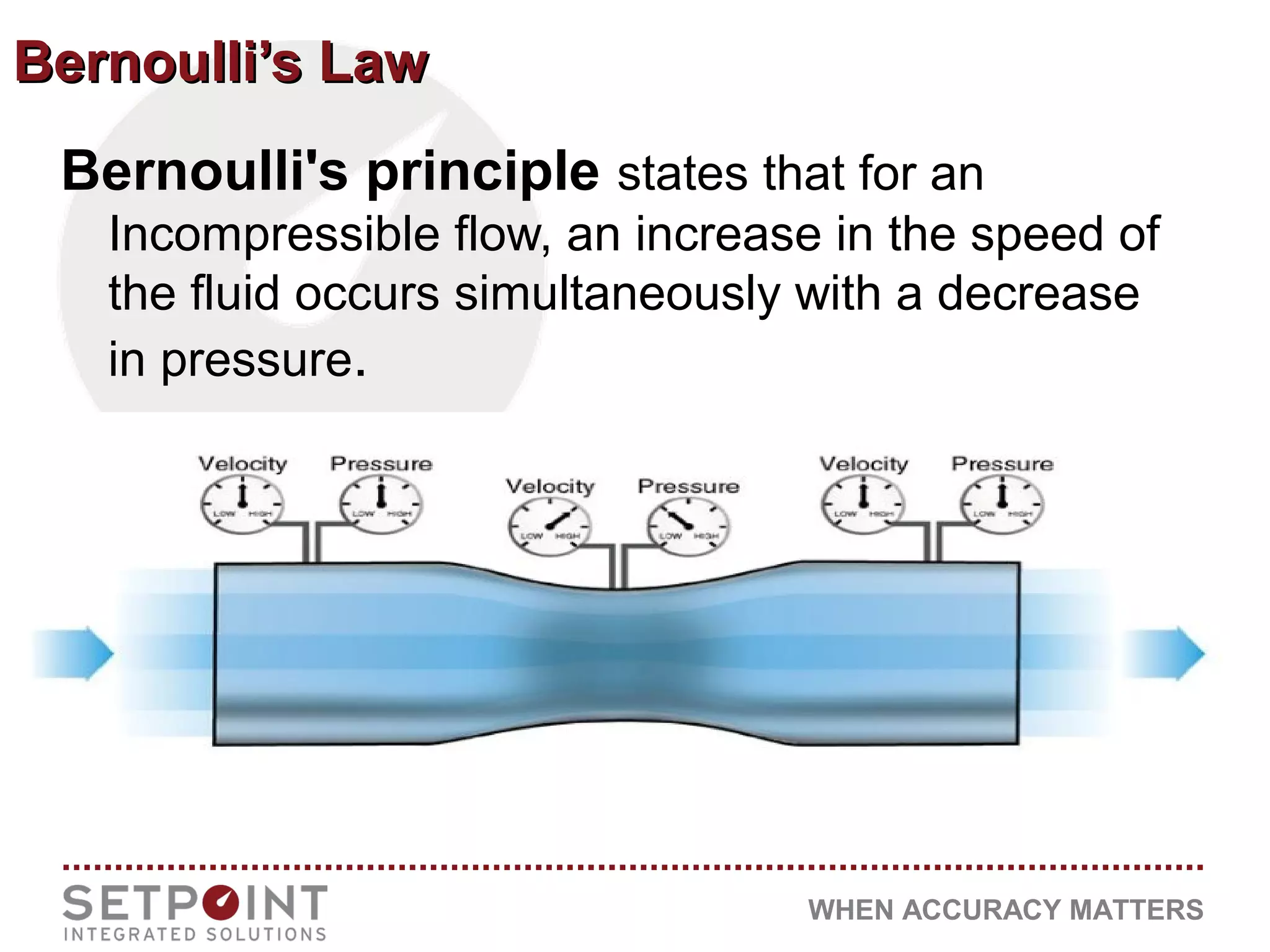
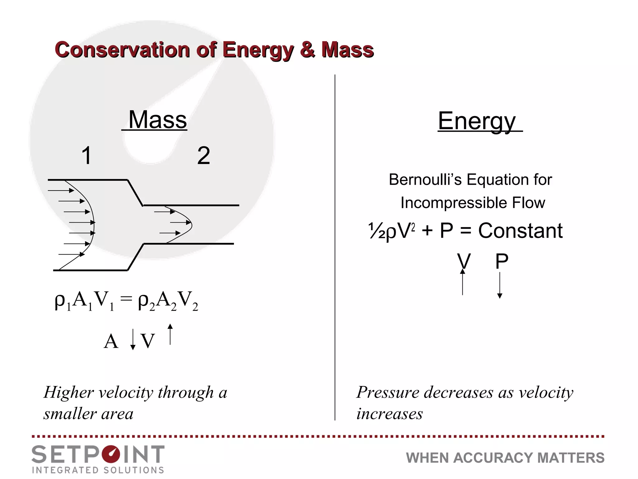
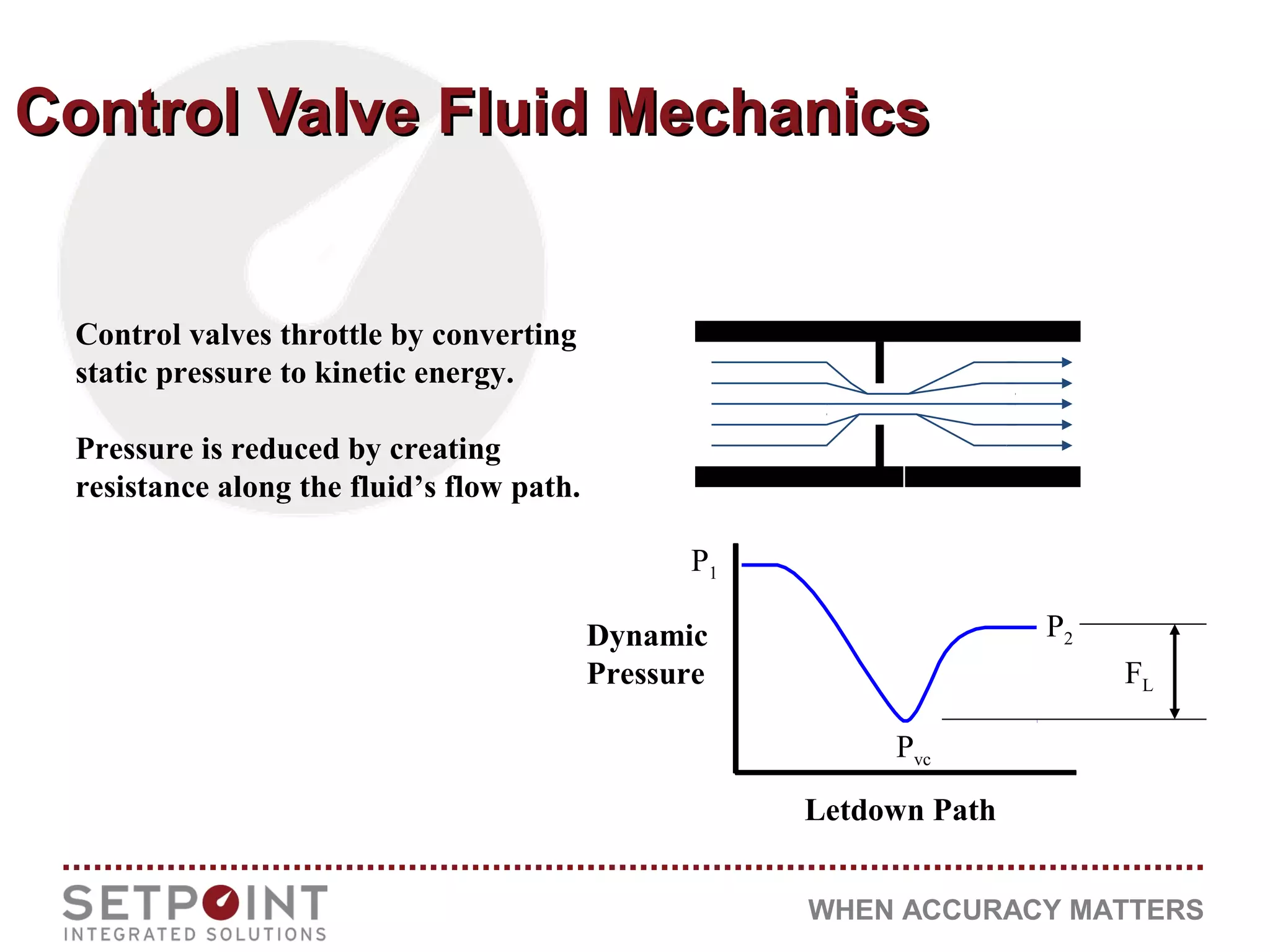
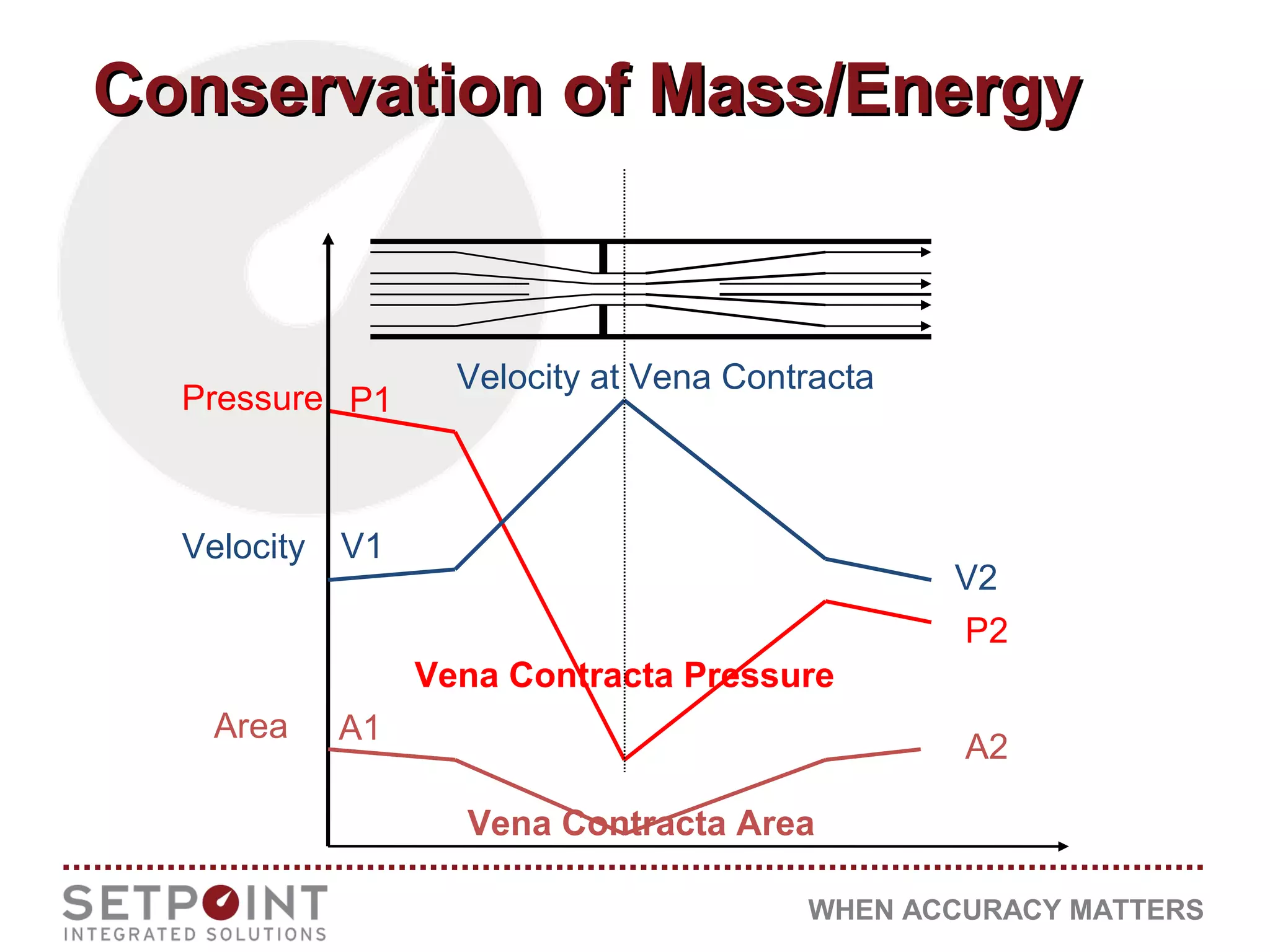
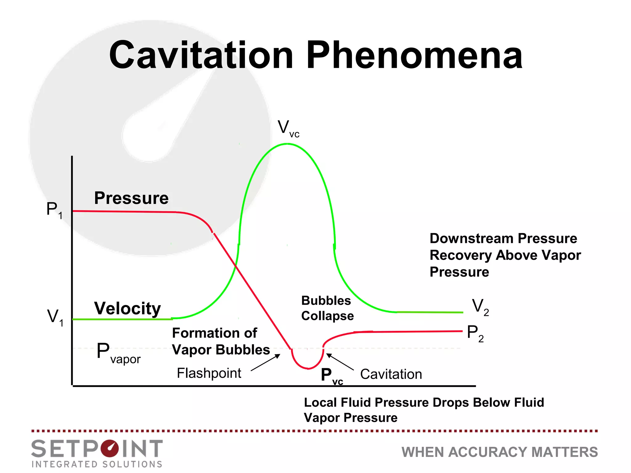
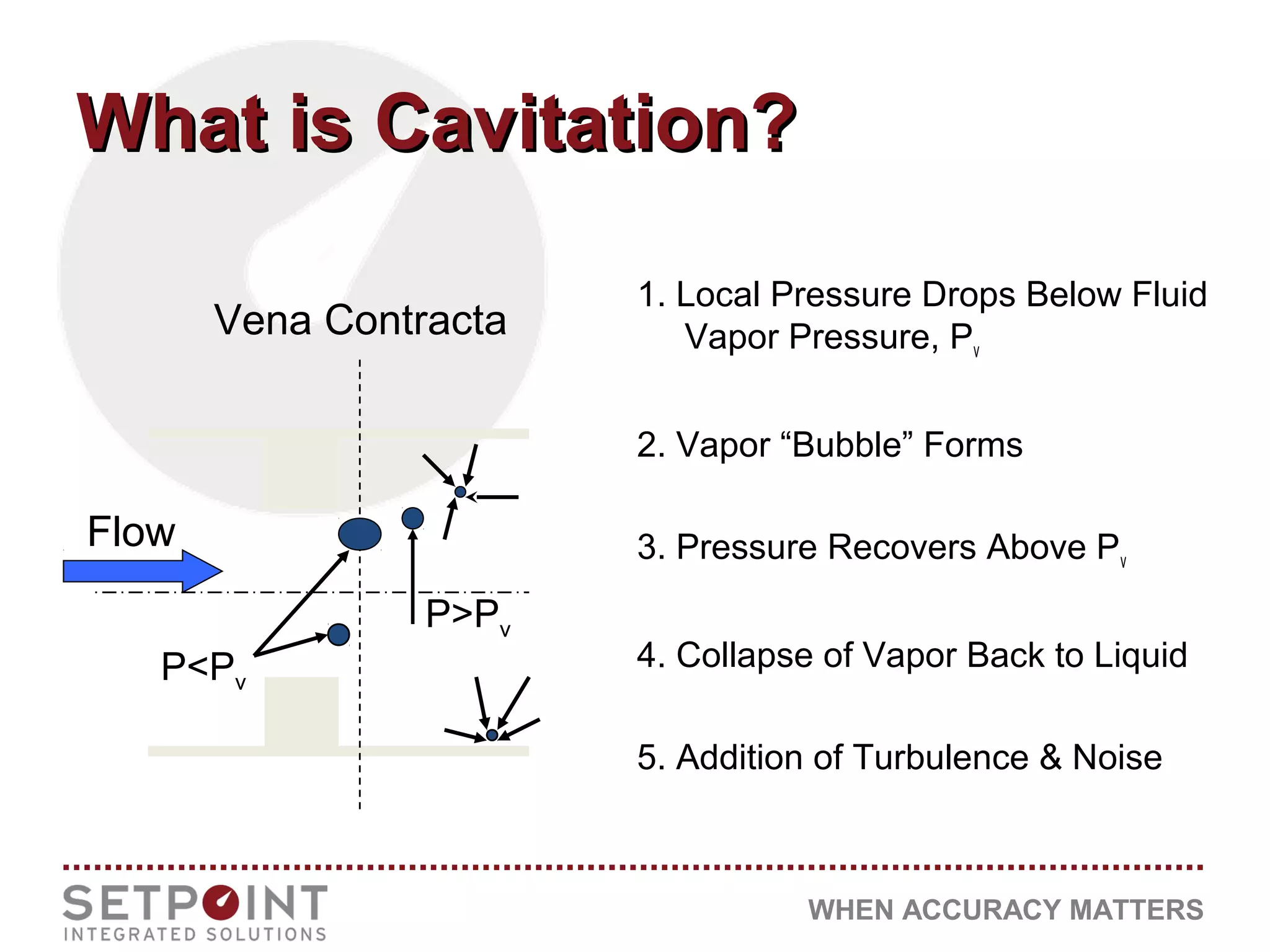
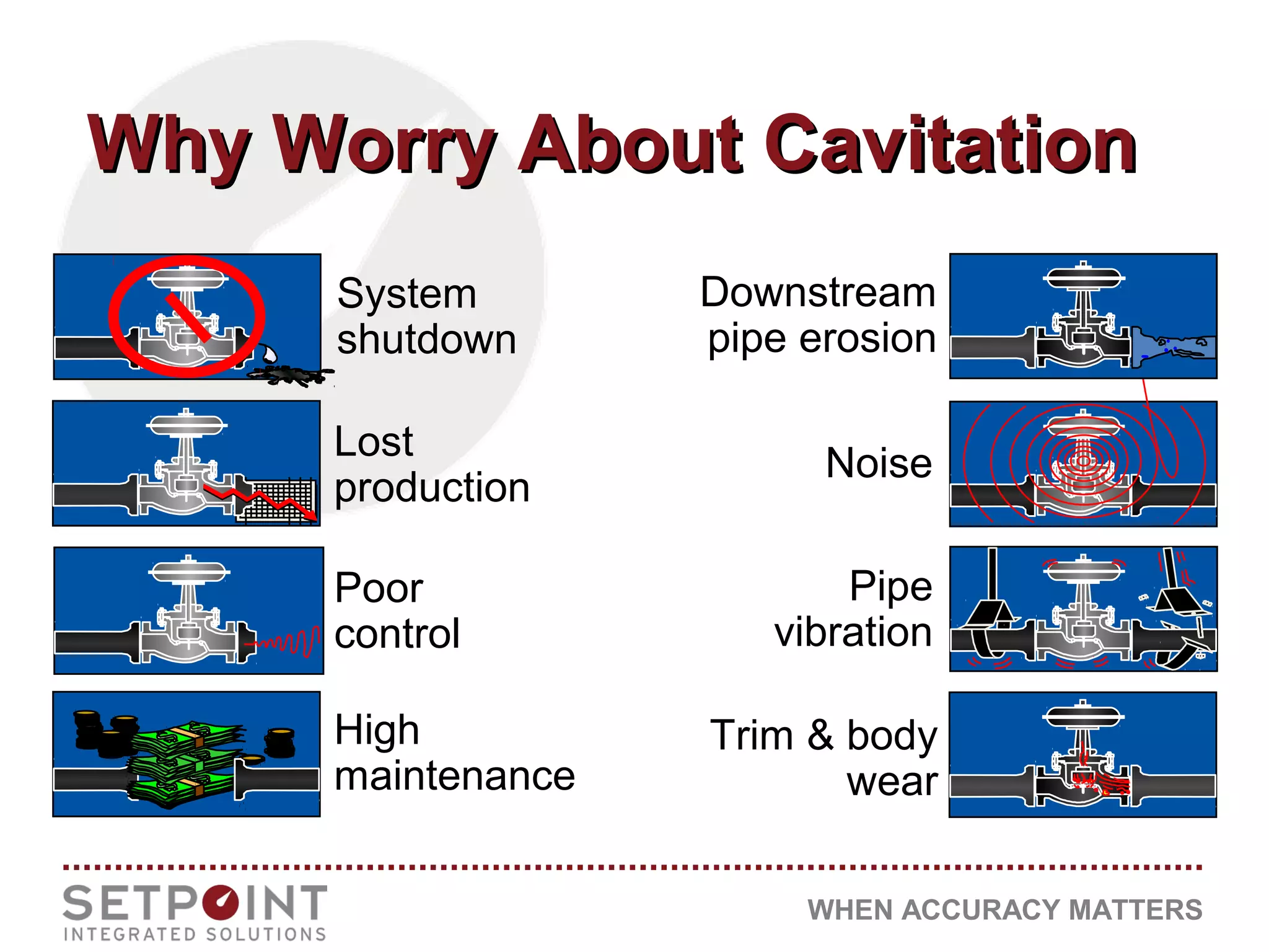
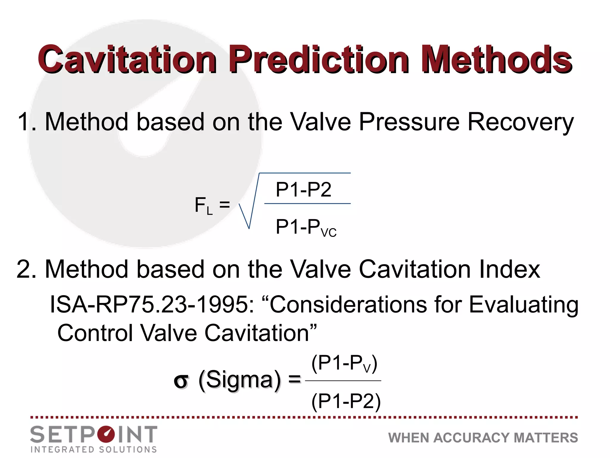
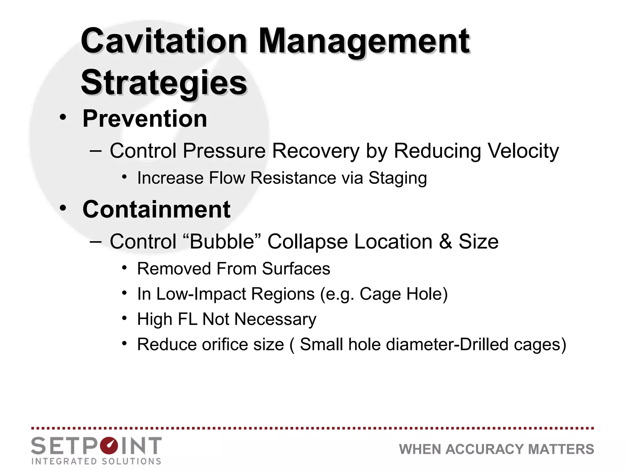
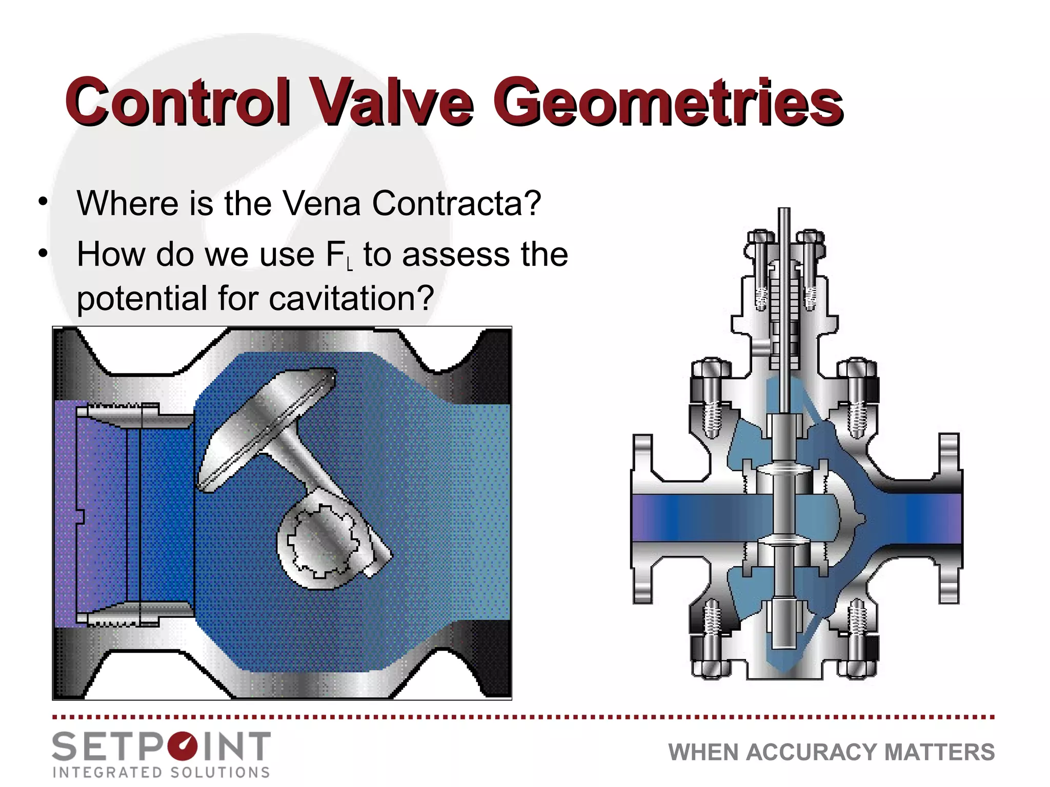
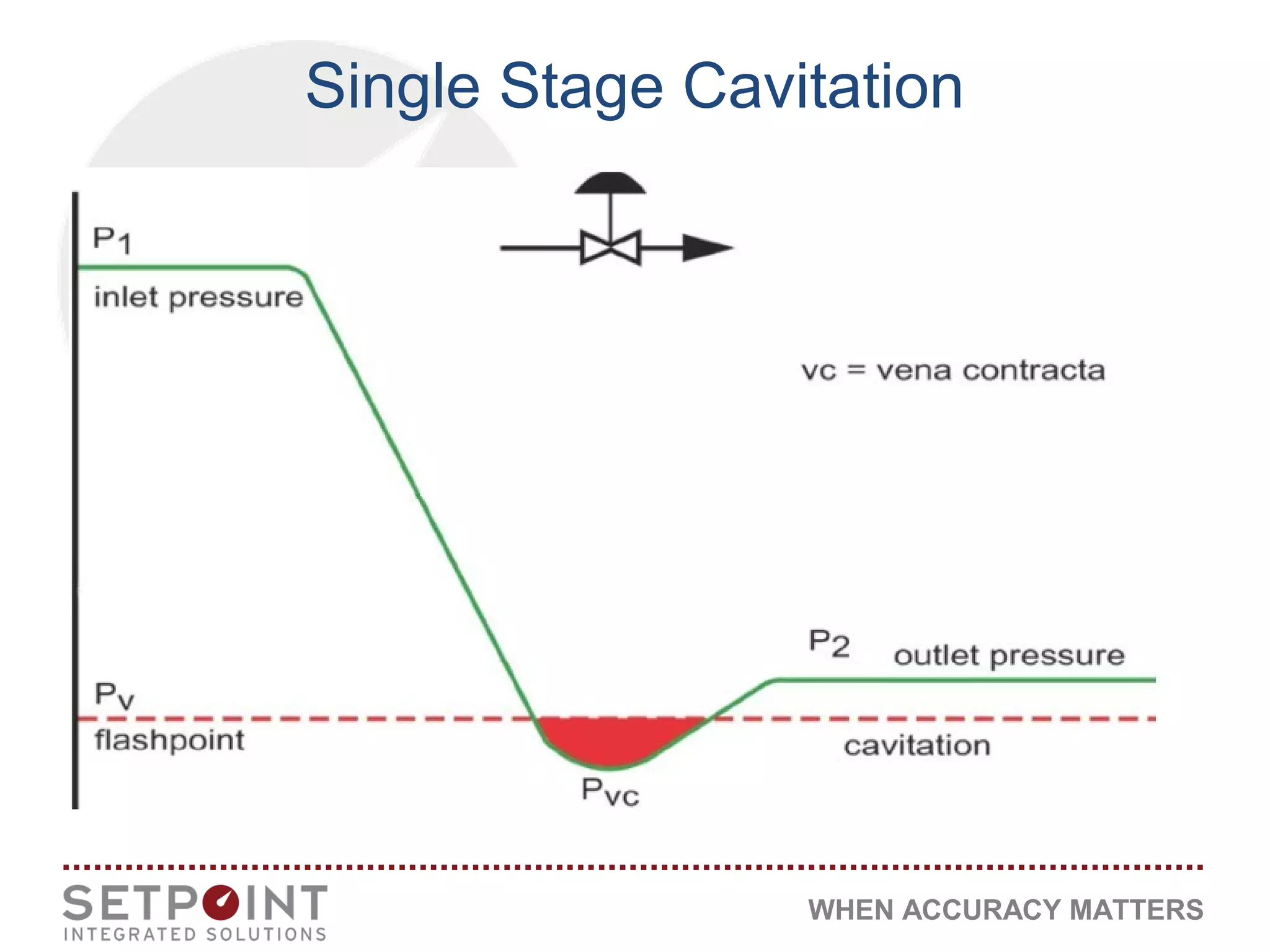


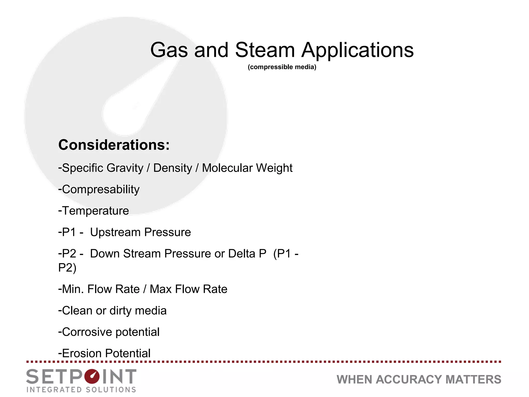
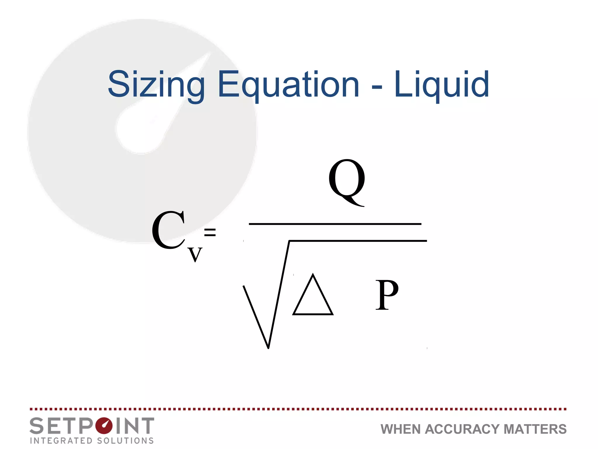
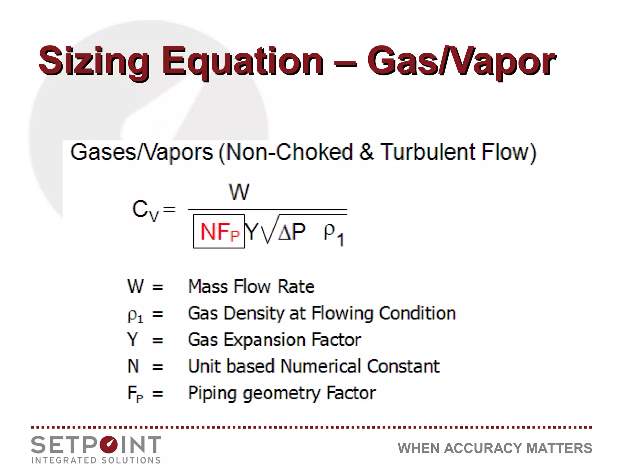


The document discusses the importance of accuracy in fluid dynamics, covering key concepts such as valve capacity, Bernoulli's law, and cavitation phenomena. It highlights the effects and management strategies for cavitation and flashing in fluid systems, emphasizing their potential impact on maintenance and operational efficiency. Additionally, it outlines considerations for selecting control valve geometries and technology to mitigate issues associated with fluid dynamics in liquid and gas applications.


