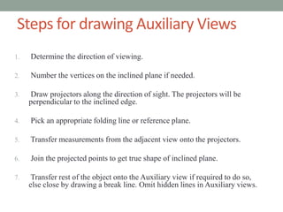
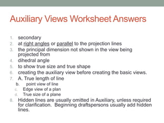
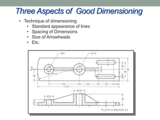
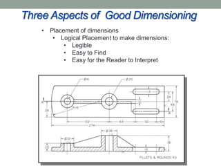
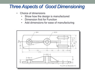
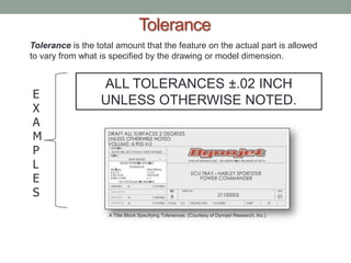
2D ESSENTIALS

Instructor: Laura Gerold, PE
Catalog #10614113
Class # 22784, 24113, 24136, & 24138
Class Start: January 18, 2012
Class End: May 16, 2012
Reminders

• Extra Credit (Write Exam Question) Due Next Week (May
  2nd)
• Final Project is due in two weeks on May 9th.
• Final Exam is in three weeks on May 16th.
Group Project – Parallel Lines
• In your groups, discuss and practice the methods that can
  be used to draw parallel lines on an object.
• Present your methods
• Group with the most methods receives an award . . .
CHAPTER 8 –
AUXILIARY VIEWS
Why Do We Need Auxiliary Views?
• Inclined Planes and Oblique lines do not appear true size
  or true length in any orthographic views
• In order to show better detail on the inclined and oblique
  planes, auxiliary views are used
• Auxiliary views are taken from an angle that is not one of
  the primary standard orthographic views


                                          Source:
                                          http://draftingmanuals.tpub.com/14040/css/14
                                          040_41.htm
What are the differences between
   primary, secondary, and successive views?
• Primary auxiliary views are projected from one of the
 principal planes (front, top, side).


         Source: http://www.pleasantville.k12.ia.us/staff/fvanderpool/pages/draftingsg.html
What are the differences between primary,
      secondary, and successive views?
• Secondary auxiliary are projected from the primary
 auxiliary plane


          Source: http://joekintercadportfolio.weebly.com/segment-8-supplemental-views.html
What are the differences between
    primary, secondary, and successive views?
• A third auxiliary view can be obtained from a projection of
 the secondary auxiliary view and so on . . . .
What are the differences between
  primary, secondary, and successive views?
• Group Project
  • Use a simple object with an inclined surface
  • Draw the necessary views
  • Draw a Primary Auxiliary View
  • Draw a Secondary Auxiliary View
  • Draw another “Successive View”
  • Present results
HIDDEN LINES IN AUXILIARY VIEWS

• Hidden Lines can
  clutter an auxiliary
  drawing and are not
  shown unless
  essential to
  understanding the
  object.
• As a beginning
  technical drawer, you
  may want to show all
  hidden lines for
  visualization practice
CIRCLES AND ELLIPSES
                 IN AUXILIARY VIEWS
Circular shapes appear elliptical when viewed at an angle other than 90° (straight
on to the circular shape). This is frequently the case when constructing auxiliary
views.
Show an Inclined Elliptical Surface True
                  Size
• Let’s practice drawing an inclined elliptical surface to true
 size in an auxiliary view.

• Practice with the Example on page 288 of the text book
Group Project – Elliptical Surfaces
• Use an object in the room, an object you brought, an
  object you find outside the room, an object in the book, or
  make up the necessary views of an elliptical surface.
• Draw an elliptical surface auxiliary view
Plotting Curves in an Auxiliary View
• Let’s practice plotting curves to draw in an auxiliary view.


• Practice with the Example on page 290 of the text book
Group Project – Plotting Curves
• Use an object in the room or make up the necessary
  views of a curved object.
• Draw a curved auxiliary view
VIEWING-PLANE LINES
                      AND ARROWS
When the drawing sheet is too crowded to show the auxiliary view in
direction projection you can use a viewing-plane line or a viewing
direction arrow to indicate the direction of sight for the auxiliary view.
Uses of Auxiliary Views
• Auxiliary Views are often used to show the following:
  • True length of a line
  • Point view of a line
  • Edge view of a plane
  • True size of a plane
TRUE LENGTH OF A LINE
To show a line true length, make the fold line parallel to the line you want to show
true length in the auxiliary view. Whenever a line is parallel to the fold line between
two views, it will be true length in the adjacent view.
TRUE LENGTH OF A LINE – EXAMPLE
• Work through the true length of a hip rafter example on
 page 295
TRUE LENGTH OF A LINE – GROUP
           PROJECT
• Use an inclined surface that you brought with you, that I
  have, or that you see around the room.
• Practice drawing the necessary views and an auxiliary
  view with the true length of one of the inclined lines.
POINT VIEW OF A LINE
To show the point view of a line, choose the direction of sight parallel to the
line where it is true length.    1. Choose the direction of sight to be parallel to
                                    line 1–2.

                                 2. Draw folding line H/F between the top and
                                 front views, as shown.

                                 3. Draw folding line F/1 perpendicular to line 1–2
                                 where it is true length, and any convenient
                                 distance from line 1–2 (front view).

                                 4. Draw projection lines from points 1 and 2 to
                                 begin creating the auxiliary view.

                                 5. Transfer points 1 and 2 to the auxiliary view at
                                 the same distance from the folding line as they
                                 are in the top view and along their respective
                                 projection lines. They will line up exactly with
                                 each other to form a point view of the line.
POINT VIEW OF A LINE
              GROUP PROJECT
• Use Picture from Previous Slide (Figure 8.26 on page 296
  of your text book)
• After locating the points, how would you draw the rest of
  the auxiliary view? Would you use a breakline? Or would
  you ever just want to show the points?
• When do you think this would be useful when creating a
  set of drawings?
EDGE VIEW OF A PLANE
To show the edge view of a plane, choose the direction of sight parallel to a
true-length line lying in the plane.

                             1. Choose the direction of sight to be parallel to line 1–2 in
                             the front view where it is already shown true length.

                             2. Draw folding line H/F between the top and front views, as
                             shown.

                             3. Draw folding line F/1 perpendicular to true-length line 1–2
                             and any convenient distance.

                             4. Draw projection lines from points 1, 2, 3, and 4 to begin
                             creating the auxiliary view.

                             5. Transfer points 1, 2, 3, and 4 to the auxiliary view at the
                             same distance from the folding line as they are in the top view
                             and along their respective projection lines. Plane 1–2–3–4
                             will appear on edge in the finished drawing.
EDGE VIEW OF A PLANE
            GROUP PROJECT
• Use Picture from Previous Slide (Figure 8.28 on page 297
  of your text book)
• After locating the edge view of the plane, how would you
  draw the rest of the auxiliary view? Would you use a
  breakline?
• When do you think this would be useful when creating a
  set of drawings?
TRUE SIZE OF AN OBLIQUE
                SURFACE
Showing the true size of a surface continues from the method presented for showing
inclined surfaces true size, where the edge view is already given. But to show an oblique
surface true size, you need first to show the oblique surface on edge and then construct a
second auxiliary view to show it true size.
TRUE SIZE OF AN OBLIQUE
               SURFACE
• Let’s practice drawing the true size of an oblique surface
 in an auxiliary view.

• Practice with the Example on page 298 of the text book
TRUE SIZE OF AN OBLIQUE
       SURFACE GROUP PROJECT
• Use an object in the room, an object you brought, an
  object you find outside the room, or Figures 8.32 or 8.33
  in the book
• Draw the true size of an oblique surface in an auxiliary
  view
Steps for drawing Auxiliary Views
1.   Determine the direction of viewing.

2.   Number the vertices on the inclined plane if needed.

3.   Draw projectors along the direction of sight. The projectors will be
     perpendicular to the inclined edge.

4.   Pick an appropriate folding line or reference plane.

5.   Transfer measurements from the adjacent view onto the projectors.

6.   Join the projected points to get true shape of inclined plane.

7.    Transfer rest of the object onto the Auxiliary view if required to do so,
     else close by drawing a break line. Omit hidden lines in Auxiliary views.
Auxiliary Views Group Real-World Project
• My husband gave a set of plans to a builder for a unique
    roof, but did not give an auxiliary view
•   The builder called him to ask how exactly to build it
•   Should he have used an auxiliary view?
•   If so, what views would you have shown? Do a quick
    sketch.
•   Picture of Finished Building
Auxiliary Views Worksheet
• As a group, work on the Auxiliary Views Worksheet
Auxiliary Views Worksheet Answers
1.        secondary
2.        at right angles or parallel to the projection lines
3.        the principal dimension not shown in the view being
          projected from
4.        dihedral angle
5.        to show true size and true shape
6.        creating the auxiliary view before creating the basic views.
7.        A. True length of line
     b.       point view of line
     c.     Edge view of a plan
     d.     True size of a plane
8.        Hidden lines are usually omitted in Auxiliary, unless required
          for clarification. Beginning draftspersons usually add hidden
          lines.
Auxiliary Views on Youtube
• http://www.youtube.com/watch?v=gzq48vBbODg
CHAPTER 10 –
DIMENSIONING
Why Do We Dimension Drawings?
• Dimensions describe the size, shape, and material of
  objects
• Give detail on how to build an object from the designer to
  the manufacturer


                                              Source:
                                              http://www.design-
                                              technology.info/IndPro
                                              d/page11.htm
UNDERSTANDING DIMENSIONING
The increasing need for precision manufacturing and interchangeability
has shifted responsibility for size control to the design engineer or detail drafter.


  Practices for dimensioning architectural
  and structural drawings are similar
  in many ways to those for dimensioning
  manufactured parts, but some practices
  differ.


 Refer to the following standards:
 • ANSI/ASME Y14.5-2009 Dimensioning and Tolerancing
 • ASME Y14.41-2003 Digital Product definition Data Practices   Automatically Generated Dimensions.
 • ASME B4.2-1978 (R1999) Preferred Metric Limits and Fits      Views and dimensions can be generated
                                                                automatically from a solid model.
                                                                (Courtesy of Robert Kincaid.)
Three Aspects of Good Dimensioning
 Technique of dimensioning

                    Placement of dimensions

                                       Choice of dimensions
Three Aspects of Good Dimensioning
 • Technique of dimensioning
    • Standard appearance of lines
    • Spacing of Dimensions
    • Size of Arrowheads
    • Etc.
Three Aspects of Good Dimensioning
    • Placement of dimensions
       • Logical Placement to make dimensions:
           • Legible
           • Easy to Find
           • Easy for the Reader to Interpret
Three Aspects of Good Dimensioning
   • Choice of dimensions
      • Show how the design is manufactured
      • Dimension first for Function
      • Add dimensions for ease of manufacturing
Tolerance
Tolerance is the total amount that the feature on the actual part is allowed
to vary from what is specified by the drawing or model dimension.


                  ALL TOLERANCES ±.02 INCH
E
                  UNLESS OTHERWISE NOTED.
X
A
M
P
L
E
S
                    A Title Block Specifying Tolerances. (Courtesy of Dynojet Research, Inc.)
Geometric Breakdown

Engineering structures are composed
largely of simple geometric shapes, such
as the
prism, cylinder, pyramid, cone, and
sphere. They may be exterior (positive)
or interior (negative) forms.
LINES USED IN DIMENSIONING
• Dimension Line
   • A thin, dark, solid line terminated by an arrowhead, indicating
     the direction and extent of a dimension
   • Usually Perpendicular to extension lines
   • The distance is indicated numerically at the midpoint of the
     dimension line, either adjacent to the dimension line, or in a
     gap provided for it.
   • First Dimension Line should be at least 3/8” away from
     object
   • Subsequent lines can be ¼” apart and should be uniform
LINES USED IN DIMENSIONING
• Extension Line
     • Thin, dark, solid line that extends from a point on a drawing to
        which a dimension refers
     • Typically Perpendicular to Dimension Lines
     • A small gap (1/16”) should be left between the extension line
        and the object
     • Extension line should extend 1/8” beyond the outermost arrow
     • An extension line does not have arrows
LINES USED IN DIMENSIONING
• Example Dimension and Extension Lines


                                          Source:
                                          http://www.theswg
                                          eek.com/2008/05/
                                          29/hide-show-
                                          extension-and-
                                          dimension-lines/
LINES USED IN DIMENSIONING
• Centerlines
    • Thin dark line alternating long and short dashes
    • Commonly used as extension lines in locating holes
       and other symmetrical features
    • When extended for dimensioning, cross over the
       other lines of a drawing with no gaps
    • End centerlines using a long dash
Guidelines for
           USING DIMENSION
         AND EXTENSION LINES
a. Shorter dimensions are nearest the object outline
b. Do not place shorter dimensions outside, which result in
   crossing extension lines
c. Okay to cross extension lines, but they should not be
   shortened
d. A dimension line should never coincide with or extend from any
   line of a drawing
Guidelines for
          USING DIMENSION
        AND EXTENSION LINES
Dimensions should be lined up and grouped together
as much as possible.
Guidelines for
                USING DIMENSION
              AND EXTENSION LINES
a) Extension and Centerlines must cross visible lines of an object in
   many cases.
b) When this occurs, do not leaves gaps
ARROWHEADS
   • Arrowheads
      • Should be uniform in size and style
         throughout the drawing
      • Length and width should have a ratio of
         3:1
      • Length of arrowhead should be about
         1/8” long
      • Should be filled in to look better


                   When you are drawing by hand and using
                   the arrowhead method in which both
                   strokes are directed toward the point, it is
                   easier to make the strokes toward yourself.
LEADERS
A leader is a thin, solid line directing attention to a note or dimension and
starting with an arrowhead or dot.


 For the Best Appearance, Make Leaders
 • near each other and parallel
 • across as few lines as possible

 Don’t Make Leaders
 • parallel to nearby lines of the drawing
 • through a corner of the view
 • across each other
 • longer than needed
 • horizontal or vertical
Group Project
• Look at the drawings on page 401 & 402 of the text
• Identify the extension, dimension, center, and leader lines
• Note the style and location of the arrowheads
DRAWING SCALE AND DIMENSIONING


                                       Drawing scale is noted in the title block. The drawing should not be scaled for
                                       dimensions. (Courtesy of Dynojet Research, Inc.)

Many standard title blocks include a
note such as:
     DO NOT SCALE DRAWING
         FOR DIMENSIONS
DIRECTION OF DIMENSION
               VALUES AND NOTES
All dimension values and notes are lettered horizontally to be read from the bottom of the
sheet, as oriented by the title block.
DIMENSION UNITS
A note stating ALL MEASUREMENTS IN MILLIMETERS or ALL MEASUREMENTS IN
INCHES UNLESS OTHERWISE NOTED is used in the title block to indicate the
measurement units…


                                                (Courtesy of Dynojet Research, Inc.)
Project Time!
• Share your projects with your group.
• Discuss dimensioning your project.
• Make a list of dimensioning questions you have about
 your project and turn it in for specific instruction next class
What’s Next?

• Finish Chapter 10 - Dimensioning
Questions?
• On one of your sketches, answer the following
 two questions:
  • What was the most useful thing that you
    learned today?
  • What do you still have questions about?
Homework
Chapter 8 Review Questions: 1,6
Chapter 8 Exercises: 8.28

Class 13 presentation

  • 1.
    2D ESSENTIALS Instructor: LauraGerold, PE Catalog #10614113 Class # 22784, 24113, 24136, & 24138 Class Start: January 18, 2012 Class End: May 16, 2012
  • 2.
    Reminders • Extra Credit(Write Exam Question) Due Next Week (May 2nd) • Final Project is due in two weeks on May 9th. • Final Exam is in three weeks on May 16th.
  • 3.
    Group Project –Parallel Lines • In your groups, discuss and practice the methods that can be used to draw parallel lines on an object. • Present your methods • Group with the most methods receives an award . . .
  • 4.
  • 5.
    Why Do WeNeed Auxiliary Views? • Inclined Planes and Oblique lines do not appear true size or true length in any orthographic views • In order to show better detail on the inclined and oblique planes, auxiliary views are used • Auxiliary views are taken from an angle that is not one of the primary standard orthographic views Source: http://draftingmanuals.tpub.com/14040/css/14 040_41.htm
  • 6.
    What are thedifferences between primary, secondary, and successive views? • Primary auxiliary views are projected from one of the principal planes (front, top, side). Source: http://www.pleasantville.k12.ia.us/staff/fvanderpool/pages/draftingsg.html
  • 7.
    What are thedifferences between primary, secondary, and successive views? • Secondary auxiliary are projected from the primary auxiliary plane Source: http://joekintercadportfolio.weebly.com/segment-8-supplemental-views.html
  • 8.
    What are thedifferences between primary, secondary, and successive views? • A third auxiliary view can be obtained from a projection of the secondary auxiliary view and so on . . . .
  • 9.
    What are thedifferences between primary, secondary, and successive views? • Group Project • Use a simple object with an inclined surface • Draw the necessary views • Draw a Primary Auxiliary View • Draw a Secondary Auxiliary View • Draw another “Successive View” • Present results
  • 10.
    HIDDEN LINES INAUXILIARY VIEWS • Hidden Lines can clutter an auxiliary drawing and are not shown unless essential to understanding the object. • As a beginning technical drawer, you may want to show all hidden lines for visualization practice
  • 11.
    CIRCLES AND ELLIPSES IN AUXILIARY VIEWS Circular shapes appear elliptical when viewed at an angle other than 90° (straight on to the circular shape). This is frequently the case when constructing auxiliary views.
  • 12.
    Show an InclinedElliptical Surface True Size • Let’s practice drawing an inclined elliptical surface to true size in an auxiliary view. • Practice with the Example on page 288 of the text book
  • 13.
    Group Project –Elliptical Surfaces • Use an object in the room, an object you brought, an object you find outside the room, an object in the book, or make up the necessary views of an elliptical surface. • Draw an elliptical surface auxiliary view
  • 14.
    Plotting Curves inan Auxiliary View • Let’s practice plotting curves to draw in an auxiliary view. • Practice with the Example on page 290 of the text book
  • 15.
    Group Project –Plotting Curves • Use an object in the room or make up the necessary views of a curved object. • Draw a curved auxiliary view
  • 16.
    VIEWING-PLANE LINES AND ARROWS When the drawing sheet is too crowded to show the auxiliary view in direction projection you can use a viewing-plane line or a viewing direction arrow to indicate the direction of sight for the auxiliary view.
  • 17.
    Uses of AuxiliaryViews • Auxiliary Views are often used to show the following: • True length of a line • Point view of a line • Edge view of a plane • True size of a plane
  • 18.
    TRUE LENGTH OFA LINE To show a line true length, make the fold line parallel to the line you want to show true length in the auxiliary view. Whenever a line is parallel to the fold line between two views, it will be true length in the adjacent view.
  • 19.
    TRUE LENGTH OFA LINE – EXAMPLE • Work through the true length of a hip rafter example on page 295
  • 20.
    TRUE LENGTH OFA LINE – GROUP PROJECT • Use an inclined surface that you brought with you, that I have, or that you see around the room. • Practice drawing the necessary views and an auxiliary view with the true length of one of the inclined lines.
  • 21.
    POINT VIEW OFA LINE To show the point view of a line, choose the direction of sight parallel to the line where it is true length. 1. Choose the direction of sight to be parallel to line 1–2. 2. Draw folding line H/F between the top and front views, as shown. 3. Draw folding line F/1 perpendicular to line 1–2 where it is true length, and any convenient distance from line 1–2 (front view). 4. Draw projection lines from points 1 and 2 to begin creating the auxiliary view. 5. Transfer points 1 and 2 to the auxiliary view at the same distance from the folding line as they are in the top view and along their respective projection lines. They will line up exactly with each other to form a point view of the line.
  • 22.
    POINT VIEW OFA LINE GROUP PROJECT • Use Picture from Previous Slide (Figure 8.26 on page 296 of your text book) • After locating the points, how would you draw the rest of the auxiliary view? Would you use a breakline? Or would you ever just want to show the points? • When do you think this would be useful when creating a set of drawings?
  • 23.
    EDGE VIEW OFA PLANE To show the edge view of a plane, choose the direction of sight parallel to a true-length line lying in the plane. 1. Choose the direction of sight to be parallel to line 1–2 in the front view where it is already shown true length. 2. Draw folding line H/F between the top and front views, as shown. 3. Draw folding line F/1 perpendicular to true-length line 1–2 and any convenient distance. 4. Draw projection lines from points 1, 2, 3, and 4 to begin creating the auxiliary view. 5. Transfer points 1, 2, 3, and 4 to the auxiliary view at the same distance from the folding line as they are in the top view and along their respective projection lines. Plane 1–2–3–4 will appear on edge in the finished drawing.
  • 24.
    EDGE VIEW OFA PLANE GROUP PROJECT • Use Picture from Previous Slide (Figure 8.28 on page 297 of your text book) • After locating the edge view of the plane, how would you draw the rest of the auxiliary view? Would you use a breakline? • When do you think this would be useful when creating a set of drawings?
  • 25.
    TRUE SIZE OFAN OBLIQUE SURFACE Showing the true size of a surface continues from the method presented for showing inclined surfaces true size, where the edge view is already given. But to show an oblique surface true size, you need first to show the oblique surface on edge and then construct a second auxiliary view to show it true size.
  • 26.
    TRUE SIZE OFAN OBLIQUE SURFACE • Let’s practice drawing the true size of an oblique surface in an auxiliary view. • Practice with the Example on page 298 of the text book
  • 27.
    TRUE SIZE OFAN OBLIQUE SURFACE GROUP PROJECT • Use an object in the room, an object you brought, an object you find outside the room, or Figures 8.32 or 8.33 in the book • Draw the true size of an oblique surface in an auxiliary view
  • 28.
    Steps for drawingAuxiliary Views 1. Determine the direction of viewing. 2. Number the vertices on the inclined plane if needed. 3. Draw projectors along the direction of sight. The projectors will be perpendicular to the inclined edge. 4. Pick an appropriate folding line or reference plane. 5. Transfer measurements from the adjacent view onto the projectors. 6. Join the projected points to get true shape of inclined plane. 7. Transfer rest of the object onto the Auxiliary view if required to do so, else close by drawing a break line. Omit hidden lines in Auxiliary views.
  • 29.
    Auxiliary Views GroupReal-World Project • My husband gave a set of plans to a builder for a unique roof, but did not give an auxiliary view • The builder called him to ask how exactly to build it • Should he have used an auxiliary view? • If so, what views would you have shown? Do a quick sketch. • Picture of Finished Building
  • 30.
    Auxiliary Views Worksheet •As a group, work on the Auxiliary Views Worksheet
  • 31.
    Auxiliary Views WorksheetAnswers 1. secondary 2. at right angles or parallel to the projection lines 3. the principal dimension not shown in the view being projected from 4. dihedral angle 5. to show true size and true shape 6. creating the auxiliary view before creating the basic views. 7. A. True length of line b. point view of line c. Edge view of a plan d. True size of a plane 8. Hidden lines are usually omitted in Auxiliary, unless required for clarification. Beginning draftspersons usually add hidden lines.
  • 32.
    Auxiliary Views onYoutube • http://www.youtube.com/watch?v=gzq48vBbODg
  • 33.
  • 34.
    Why Do WeDimension Drawings? • Dimensions describe the size, shape, and material of objects • Give detail on how to build an object from the designer to the manufacturer Source: http://www.design- technology.info/IndPro d/page11.htm
  • 35.
    UNDERSTANDING DIMENSIONING The increasingneed for precision manufacturing and interchangeability has shifted responsibility for size control to the design engineer or detail drafter. Practices for dimensioning architectural and structural drawings are similar in many ways to those for dimensioning manufactured parts, but some practices differ. Refer to the following standards: • ANSI/ASME Y14.5-2009 Dimensioning and Tolerancing • ASME Y14.41-2003 Digital Product definition Data Practices Automatically Generated Dimensions. • ASME B4.2-1978 (R1999) Preferred Metric Limits and Fits Views and dimensions can be generated automatically from a solid model. (Courtesy of Robert Kincaid.)
  • 36.
    Three Aspects ofGood Dimensioning Technique of dimensioning Placement of dimensions Choice of dimensions
  • 37.
    Three Aspects ofGood Dimensioning • Technique of dimensioning • Standard appearance of lines • Spacing of Dimensions • Size of Arrowheads • Etc.
  • 38.
    Three Aspects ofGood Dimensioning • Placement of dimensions • Logical Placement to make dimensions: • Legible • Easy to Find • Easy for the Reader to Interpret
  • 39.
    Three Aspects ofGood Dimensioning • Choice of dimensions • Show how the design is manufactured • Dimension first for Function • Add dimensions for ease of manufacturing
  • 40.
    Tolerance Tolerance is thetotal amount that the feature on the actual part is allowed to vary from what is specified by the drawing or model dimension. ALL TOLERANCES ±.02 INCH E UNLESS OTHERWISE NOTED. X A M P L E S A Title Block Specifying Tolerances. (Courtesy of Dynojet Research, Inc.)
  • 41.
    Geometric Breakdown Engineering structuresare composed largely of simple geometric shapes, such as the prism, cylinder, pyramid, cone, and sphere. They may be exterior (positive) or interior (negative) forms.
  • 42.
    LINES USED INDIMENSIONING • Dimension Line • A thin, dark, solid line terminated by an arrowhead, indicating the direction and extent of a dimension • Usually Perpendicular to extension lines • The distance is indicated numerically at the midpoint of the dimension line, either adjacent to the dimension line, or in a gap provided for it. • First Dimension Line should be at least 3/8” away from object • Subsequent lines can be ¼” apart and should be uniform
  • 43.
    LINES USED INDIMENSIONING • Extension Line • Thin, dark, solid line that extends from a point on a drawing to which a dimension refers • Typically Perpendicular to Dimension Lines • A small gap (1/16”) should be left between the extension line and the object • Extension line should extend 1/8” beyond the outermost arrow • An extension line does not have arrows
  • 44.
    LINES USED INDIMENSIONING • Example Dimension and Extension Lines Source: http://www.theswg eek.com/2008/05/ 29/hide-show- extension-and- dimension-lines/
  • 45.
    LINES USED INDIMENSIONING • Centerlines • Thin dark line alternating long and short dashes • Commonly used as extension lines in locating holes and other symmetrical features • When extended for dimensioning, cross over the other lines of a drawing with no gaps • End centerlines using a long dash
  • 46.
    Guidelines for USING DIMENSION AND EXTENSION LINES a. Shorter dimensions are nearest the object outline b. Do not place shorter dimensions outside, which result in crossing extension lines c. Okay to cross extension lines, but they should not be shortened d. A dimension line should never coincide with or extend from any line of a drawing
  • 47.
    Guidelines for USING DIMENSION AND EXTENSION LINES Dimensions should be lined up and grouped together as much as possible.
  • 48.
    Guidelines for USING DIMENSION AND EXTENSION LINES a) Extension and Centerlines must cross visible lines of an object in many cases. b) When this occurs, do not leaves gaps
  • 49.
    ARROWHEADS • Arrowheads • Should be uniform in size and style throughout the drawing • Length and width should have a ratio of 3:1 • Length of arrowhead should be about 1/8” long • Should be filled in to look better When you are drawing by hand and using the arrowhead method in which both strokes are directed toward the point, it is easier to make the strokes toward yourself.
  • 50.
    LEADERS A leader isa thin, solid line directing attention to a note or dimension and starting with an arrowhead or dot. For the Best Appearance, Make Leaders • near each other and parallel • across as few lines as possible Don’t Make Leaders • parallel to nearby lines of the drawing • through a corner of the view • across each other • longer than needed • horizontal or vertical
  • 51.
    Group Project • Lookat the drawings on page 401 & 402 of the text • Identify the extension, dimension, center, and leader lines • Note the style and location of the arrowheads
  • 52.
    DRAWING SCALE ANDDIMENSIONING Drawing scale is noted in the title block. The drawing should not be scaled for dimensions. (Courtesy of Dynojet Research, Inc.) Many standard title blocks include a note such as: DO NOT SCALE DRAWING FOR DIMENSIONS
  • 53.
    DIRECTION OF DIMENSION VALUES AND NOTES All dimension values and notes are lettered horizontally to be read from the bottom of the sheet, as oriented by the title block.
  • 54.
    DIMENSION UNITS A notestating ALL MEASUREMENTS IN MILLIMETERS or ALL MEASUREMENTS IN INCHES UNLESS OTHERWISE NOTED is used in the title block to indicate the measurement units… (Courtesy of Dynojet Research, Inc.)
  • 55.
    Project Time! • Shareyour projects with your group. • Discuss dimensioning your project. • Make a list of dimensioning questions you have about your project and turn it in for specific instruction next class
  • 56.
    What’s Next? • FinishChapter 10 - Dimensioning
  • 57.
    Questions? • On oneof your sketches, answer the following two questions: • What was the most useful thing that you learned today? • What do you still have questions about?
  • 58.
    Homework Chapter 8 ReviewQuestions: 1,6 Chapter 8 Exercises: 8.28