Downloaded 864 times

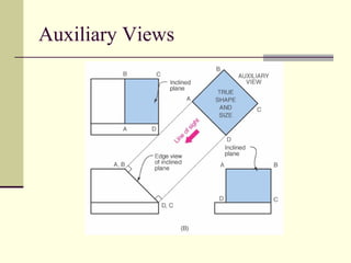
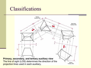
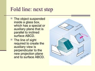
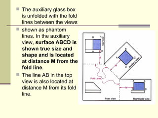
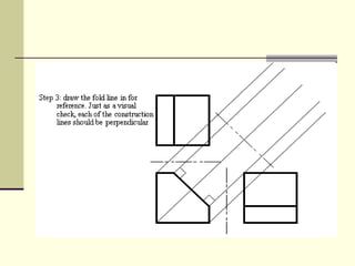
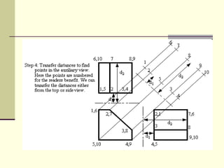
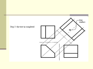


Auxiliary views are orthographic projections used to show the true size and shape of inclined or oblique surfaces that cannot be fully represented in the standard three views. Auxiliary views are projected from principal views or other auxiliary views. They are used when features need to be shown at their true size for dimensioning or determining measurements like dihedral angles between surfaces. Multiple successive auxiliary views can be created by projecting additional views from existing auxiliary views.


![8. Auxilary Projections with example [Repaired].pptx](https://cdn.slidesharecdn.com/ss_thumbnails/8-240304062220-18bbd917-thumbnail.jpg?width=640&height=640&fit=bounds)