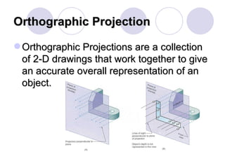
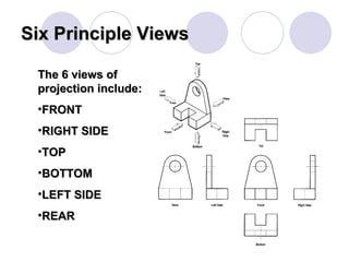
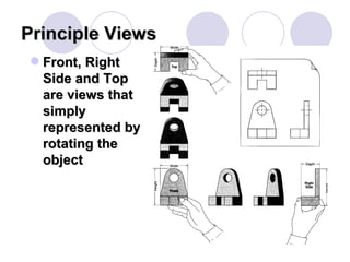
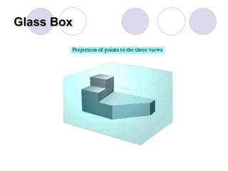
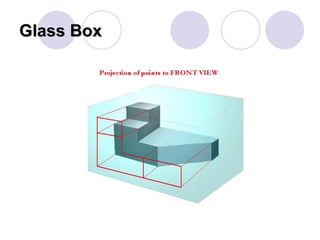
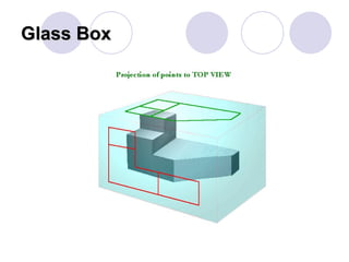
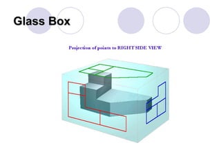
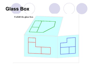
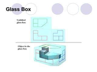
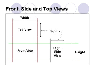
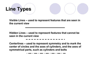
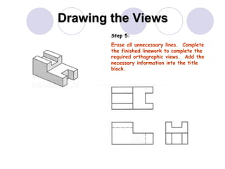
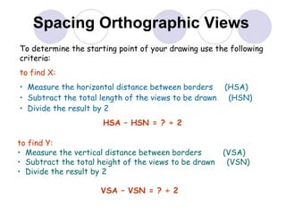
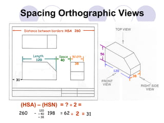
Orthographic Projection Drawing Technological Design TDJ3M0 - Grade 11
Agenda Orthographic Projection 6 Principle Views Rules of Orthographic Projection Principle Views Glass Box Line Types Example – Orthographic Projection
Orthographic Projection Orthographic Projections are a collection of 2-D drawings that work together to give an accurate overall representation of an object.
Six Principle Views The 6 views of projection include: FRONT RIGHT SIDE TOP BOTTOM LEFT SIDE REAR
Rules of Orthographic Drawing Pick a Front View that is most descriptive of object, normally the longest dimension is chosen as the width (or depth) Most common combination of views is to use are  Front, Top, and Side View
Principle Views Front, Right Side and Top are views that simply represented by rotating the object
Glass Box Most powerful technique to understand orthographic projections Suspend the object with transparent strings inside a glass box Freeze the view from each direction (each of the six sides of the box) and unfold the box
Glass Box
Glass Box
Glass Box
Glass Box
Glass Box
Glass Box
Front, Side and Top Views Height Depth Width Front View Top View Right Side View
Line Types Visible Lines – used to represent features that are seen in the current view Hidden Lines – used to represent features that cannot be seen in the current view Centerlines – used to represent symmetry and to mark the center of circles and the axes of cylinders, and the axes of symmetrical parts, such as cylinders and bolts
Example 1.  Visible 2.  Hidden 3.  Center
Drawing the Views To  complete  an orthographic projection drawing follow these steps. Step 1:  Lightly construct the front view. Step 2:  Space the top view 25-40 mm above the front view.  Lightly construct the top view directly over the front view.  Extend the lower side of the top view to intersect a vertical line drawn to the right of the front view. 25-40 mm
Drawing the Views The use of a 45 o  mitre line helps to project features from the top view to the side view. Step 3: Project the features of the front view to the right of the vertical line.  Draw a line at 45 o  from the point of intersection as shown.
Drawing the Views Step 4: Where the horizontal projection lines of the top view intersect with the mitre line, draw vertical projection lines to the side view.
Drawing the Views Step 5: Erase all unnecessary lines.  Complete the finished linework to complete the required orthographic views.  Add the necessary information into the title block.
To determine the starting point of your drawing use the following criteria: to find X: Measure the horizontal distance between borders  (HSA) Subtract the total length of the views to be drawn  (HSN) Divide the result by 2 HSA – HSN = ? ÷ 2 to find Y:  Measure the vertical distance between borders  (VSA) Subtract the total height of the views to be drawn  (VSN) Divide the result by 2 VSA – VSN = ? ÷ 2 Spacing Orthographic Views
Spacing Orthographic Views (HSA) – (HSN)  = ?  ÷  2 = 260  - = 62 ÷  2 =  31 Distance between borders  HSA  260 Length   120 Width   38 Space 40 120 56 38 31 120  + 40 + 38 198

Lesson 2 orthographic drawing - tdj3 m0

  • 1.
    Orthographic Projection DrawingTechnological Design TDJ3M0 - Grade 11
  • 2.
    Agenda Orthographic Projection6 Principle Views Rules of Orthographic Projection Principle Views Glass Box Line Types Example – Orthographic Projection
  • 3.
    Orthographic Projection OrthographicProjections are a collection of 2-D drawings that work together to give an accurate overall representation of an object.
  • 4.
    Six Principle ViewsThe 6 views of projection include: FRONT RIGHT SIDE TOP BOTTOM LEFT SIDE REAR
  • 5.
    Rules of OrthographicDrawing Pick a Front View that is most descriptive of object, normally the longest dimension is chosen as the width (or depth) Most common combination of views is to use are Front, Top, and Side View
  • 6.
    Principle Views Front,Right Side and Top are views that simply represented by rotating the object
  • 7.
    Glass Box Mostpowerful technique to understand orthographic projections Suspend the object with transparent strings inside a glass box Freeze the view from each direction (each of the six sides of the box) and unfold the box
  • 8.
  • 9.
  • 10.
  • 11.
  • 12.
  • 13.
  • 14.
    Front, Side andTop Views Height Depth Width Front View Top View Right Side View
  • 15.
    Line Types VisibleLines – used to represent features that are seen in the current view Hidden Lines – used to represent features that cannot be seen in the current view Centerlines – used to represent symmetry and to mark the center of circles and the axes of cylinders, and the axes of symmetrical parts, such as cylinders and bolts
  • 16.
    Example 1. Visible 2. Hidden 3. Center
  • 17.
    Drawing the ViewsTo complete an orthographic projection drawing follow these steps. Step 1: Lightly construct the front view. Step 2: Space the top view 25-40 mm above the front view. Lightly construct the top view directly over the front view. Extend the lower side of the top view to intersect a vertical line drawn to the right of the front view. 25-40 mm
  • 18.
    Drawing the ViewsThe use of a 45 o mitre line helps to project features from the top view to the side view. Step 3: Project the features of the front view to the right of the vertical line. Draw a line at 45 o from the point of intersection as shown.
  • 19.
    Drawing the ViewsStep 4: Where the horizontal projection lines of the top view intersect with the mitre line, draw vertical projection lines to the side view.
  • 20.
    Drawing the ViewsStep 5: Erase all unnecessary lines. Complete the finished linework to complete the required orthographic views. Add the necessary information into the title block.
  • 21.
    To determine thestarting point of your drawing use the following criteria: to find X: Measure the horizontal distance between borders (HSA) Subtract the total length of the views to be drawn (HSN) Divide the result by 2 HSA – HSN = ? ÷ 2 to find Y: Measure the vertical distance between borders (VSA) Subtract the total height of the views to be drawn (VSN) Divide the result by 2 VSA – VSN = ? ÷ 2 Spacing Orthographic Views
  • 22.
    Spacing Orthographic Views(HSA) – (HSN) = ? ÷ 2 = 260 - = 62 ÷ 2 = 31 Distance between borders HSA 260 Length 120 Width 38 Space 40 120 56 38 31 120 + 40 + 38 198